manuals.online logo
Brands
  1. Home
  2. •
  3. Brands
  4. •
  5. Veris Industries
  6. •
  7. Measuring Instrument
  8. •
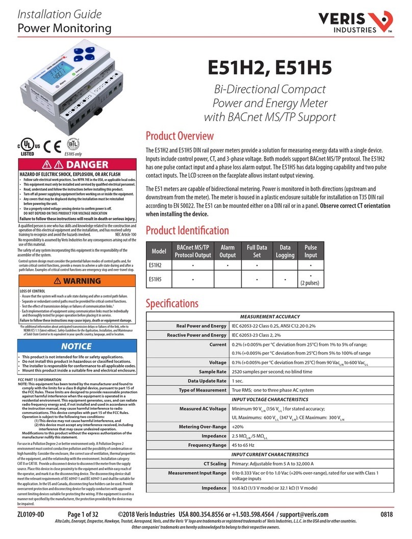
  9. Veris Industries H5004 User manual

Veris Industries H5004 User manual

6%2)3).$5342)%3
CURRENT MONITORING INSTALLATION GUIDE
Z201171-0A PAGE 1 ©2008 Veris Industries USA 800.354.8556 or 503.598.4564 / suppor[email protected] 09083
Alta Labs, Enercept, Enspector, Hawkeye, Trustat, Veris, and the Veris ‘V’ logo are trademarks or registered trademarks of Veris Industries, L.L.C. in the USA and/or other countries.
Current Sensing Four-Point
Remote Status Panel/Sensor Kit
Installer’s Specifications
Temperature Range -15° to 85°C (5° to 185°F)
Humidity Range 0 - 95% non-condensing
Trip Point Adjustable
Hysteresis 10% Typical
Output Type Dry Contact, reed relay, N.O.
Output Rating 200mA@30VAC/DC
50mA@120VAC
No. of Points Accepted 1-4 sensors (H5800 solid core)
Supply Voltage 24VAC/DC
Supply Current 50mA max.
Housing NEMA 1
H5800 Current Sensor:
Amperage Ratings 1 to 100A continuous
Wiring Up to 1000’ from panel, 2 wire, 22 AWG twisted pair
All outputs and adjustments are per point.
Do not use the LED status indicators as evidence.
)";"3%0'&-&$53*$4)0$,&91-04*0/03"3$'-"4)
t 'PMMPXTBGFFMFDUSJDBMXPSLQSBDUJDFT
4FF/'1"&JOUIF64"PSBQQMJDBCMFMPDBMDPEFT
t 5IJTFRVJQNFOUNVTUPOMZCFJOTUBMMFEBOETFSWJDFECZRVBMJmFEFMFDUSJDBMQFSTPOOFM
t 3FBEVOEFSTUBOEBOEGPMMPXUIFJOTUSVDUJPOTCFGPSFJOTUBMMJOHUIJTQSPEVDU
t 5VSOPõBMMQPXFSTVQQMZJOHFRVJQNFOUCFGPSFXPSLJOHPOPSJOTJEFUIFFRVJQNFOU
t 6TFBQSPQFSMZSBUFEWPMUBHFTFOTJOHEFWJDFUPDPOmSNQPXFSJTPõ
%0/05%&1&/%0/5)*4130%6$5'0370-5"(&*/%*$"5*0/
t 0OMZJOTUBMMUIJTQSPEVDUPOJOTVMBUFEDPOEVDUPST
'BJMVSFUPGPMMPXUIFTFJOTUSVDUJPOTXJMMSFTVMUJOEFBUIPSTFSJPVTJOKVSZ
%"/(&3
Wiring ExamplE
H5004/H5004C 5004/5004C
DimEnsions
/05*$&
t 5IJTQSPEVDUJTOPUJOUFOEFEGPSMJGFPSTBGFUZBQQMJDBUJPOT
t %POPUJOTUBMMUIJTQSPEVDUJOIB[BSEPVTPSDMBTTJmFEMPDBUJPOT
t 5IFJOTUBMMFSJTSFTQPOTJCMFGPSDPOGPSNBODFUPBMMBQQMJDBCMFDPEFT
t .PVOUUIJTQSPEVDUJOTJEFBTVJUBCMFmSFBOEFMFDUSJDBMFODMPTVSF
quick install
Disconnect and lock out power to the conductor to be monitored.1.
Install the Remote Status Panel near the controller. Wire the supply voltage2.
terminal to 24VAC/DC power source.
Slide the conductors to be monitored through the sensing irises of the current3.
transducers (up to 4 transducers per Panel). See Notes (page 2) for currents under
1 Amp or above 100 Amp. Note: Transducers may be located up to 1000 feet from
the Remote Status Panel.
Wire the output connections between the sensors and the Remote Status Panel.4.
See Wiring section (page 2) for details. Sensors are polarity sensitive.
Adjust the amperage setpoint at which the Panel output will trip. Turn clockwise5.
to increase.
Reconnect power.6.
Motor
Control Center
Digital Control
Fan/pump #1
Hawkeye 5000
Adjustable Current
Status Sensor
Fan/pump #2
Starters H5800 Mini-Sensor
Digital
Status
Inputs
4.2”
(105 mm)
2.75”
(70 mm)
Ø = 0.7”
(18 mm)
1.8”
(46 mm)
2.5”
(64 mm)
2.3”
(58 mm)
0.9”
(22 mm)
H5004
H5004C
proDuct iDEntification
Model Description
H5004 Remote Status Panel
H5004C Remote Status Panel Kit (includes four H5800 current sensors)
H5800 Current Sensors, sold separately
6%2)3).$5342)%3
INSTALLATION GUIDE
H5004/H5004C
Z201171-0A PAGE 2 ©2008 Veris Industries USA 800.354.8556 or 503.598.4564 / suppor[email protected] 09083
Alta Labs, Enercept, Enspector, Hawkeye, Trustat, Veris, and the Veris ‘V’ logo are trademarks or registered trademarks of Veris Industries, L.L.C. in the USA and/or other countries.
opEration
The H5004 Remote Status Panel is capable of simultaneously tracking the output
from up to four separate current transducers and displaying the operation status of
those conductors in one convenient location. LEDs indicators on the Panel’s face show
the active status of each conductor. The H5004C Panel Kit includes four H5800 mini
solid-core transducers, with a range of 1 to 100A. These sensors can be installed up
to 1000 feet from the H5004 Panel. The H5004 requires 24VAC/DC external power to
generate its output.
notEs
For load currents less than sensor minimum rating:
Wrap the monitored conductor through the center hole and around the sensor body
to produce multiple turns through the "window." This increases the current measured
by the transducer.
Controller must be programmed to account for
the extra turns. e.g., if four turns pass through
the sensor (as shown) the normal controller
reading must be divided by 4.
< 1A (sensor min.)
4x
0.5A
DANGER: 5A CTs can present hazardous voltages.
Install CTs in accordance with manufacturer's instructions.
Terminate the CT secondary before applying current.
H681x-5A CT
240A
300A:5A
4A
> 100A (H5800 max.)
For load currents greater than sensor maximum rating:
Use a 5 Amp (H681x series) Current Transformer (CT) as shown.
CAUTION
RISK OF EQUIPMENT DAMAGE
t %FSBUFUIFQSPEVDUTNBYJNVNDVSSFOUGPSUIFOVNCFSPGUVSOT
UISPVHIUIFTFOTJOHXJOEPXVTJOHUIFGPMMPXJOHGPSNVMB
3BUFE.BY"NQT/VNCFSPG5VSOT.BYNPOJUPSFE"NQT
FH"5VSOT"NQTNBYJONPOJUPSFEDPOEVDUPS
t 'BJMVSFUPGPMMPXUIFTFJOTUSVDUJPOTDBOSFTVMUJOPWFSIFBUJOH
BOEQFSNBOFOUFRVJQNFOUEBNBHF
Wiring
Power
24 VAC/DC
Power Supply
24 VAC/DC IN
_
+
_
+
_
+
_
+
_
+
_
+
_
+
_
+
Sensor 1 Status 1 Output 1
Output 2
Output 3
Output 4
Status 2
Status 3
Status 4
Sensor 2
Sensor 3
Sensor 4
Use Veris H5800 current sensors only. H5004 Remote Status Panel Building Control Panel
Digital
Inputs
Power Input
troublEshooting
Problem Solution
No reading at controller · Check that + and - polarity is observed in
the wiring.
calibration
Before beginning calibration, establish normal load conditions.
A. To monitor under-current (belt loss, coupling shear, status):
"
OK!
!
OK!
"
OK!
1. Turn setpoint screw counterclockwise
until Status LED turns on.
2. Slowly turn the screw clockwise to find
the point at which the Status LED just turns
off.
Turn the screw an additional ¼ turn
counter-clockwise from the position
determined in step 2 above. The Status LED
should be ON. The sensor is now calibrated to
indicate amperage flow below normal levels.
B. To monitor over-current (mechanical problems, seized impeller):
"
OK!
!
OK!
45"564
OK!
45"564

4FUQPJOU

4FUQPJOU
Setpoint Status
Setpoint Status
STOP
The sensor threshold is now balanced at the amperage level being
monitored. Proceed to A or B below.
Turn the screw an additional ¼ turn clockwise
from the position determined in step 2 above. If
the current exceeds this trip point, the contact
will close.
H5800 sensor
H5800 sensor

This manual suits for next models

2

Other Veris Industries Measuring Instrument manuals
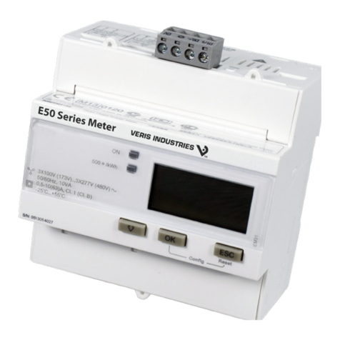
Veris Industries E50H2A User manual

Veris Industries

Veris Industries E50H2A User manual

Veris Industries E50F2A User manual

Veris Industries

Veris Industries E50F2A User manual

Veris Industries ENERCEPT H8051 Series User manual

Veris Industries

Veris Industries ENERCEPT H8051 Series User manual

Veris Industries E51C2A User manual

Veris Industries

Veris Industries E51C2A User manual

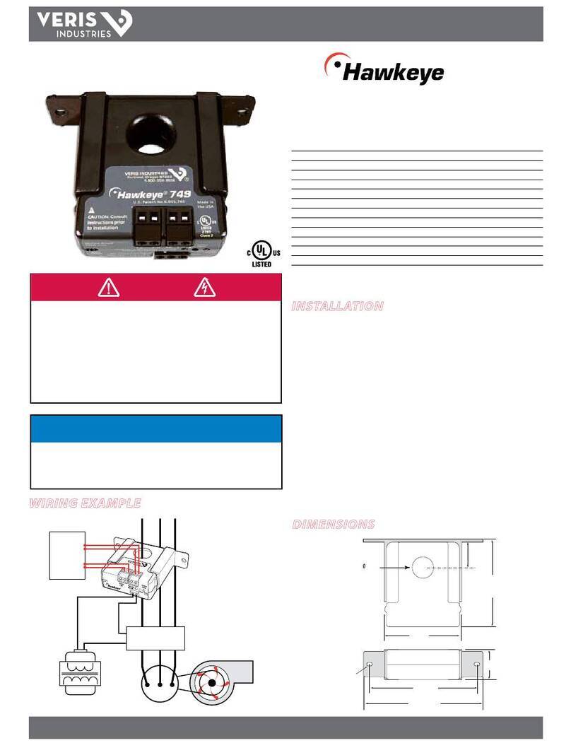
Veris Industries Hawkeye H749 User manual

Veris Industries

Veris Industries Hawkeye H749 User manual

Veris Industries FSR Series User manual

Veris Industries

Veris Industries FSR Series User manual

Veris Industries E51H2 User manual

Veris Industries

Veris Industries E51H2 User manual

Veris Industries ENERCEPT H8035 User manual

Veris Industries

Veris Industries ENERCEPT H8035 User manual

Veris Industries E50H Series User manual

Veris Industries

Veris Industries E50H Series User manual

Veris Industries E34 Series User manual

Veris Industries

Veris Industries E34 Series User manual

Veris Industries E50C1 User manual

Veris Industries

Veris Industries E50C1 User manual

Veris Industries E50 Series User manual

Veris Industries

Veris Industries E50 Series User manual

Veris Industries E50C2 User manual

Veris Industries

Veris Industries E50C2 User manual

Veris Industries E31A004 User manual

Veris Industries

Veris Industries E31A004 User manual

Veris Industries E54C3C User manual

Veris Industries

Veris Industries E54C3C User manual

Veris Industries H8150-1600-4-3 User manual

Veris Industries

Veris Industries H8150-1600-4-3 User manual

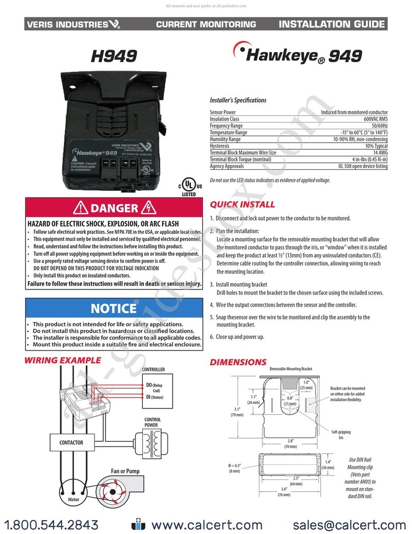
Veris Industries Hawkeye H949 User manual

Veris Industries

Veris Industries Hawkeye H949 User manual

Veris Industries H81 Series User manual

Veris Industries

Veris Industries H81 Series User manual

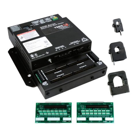
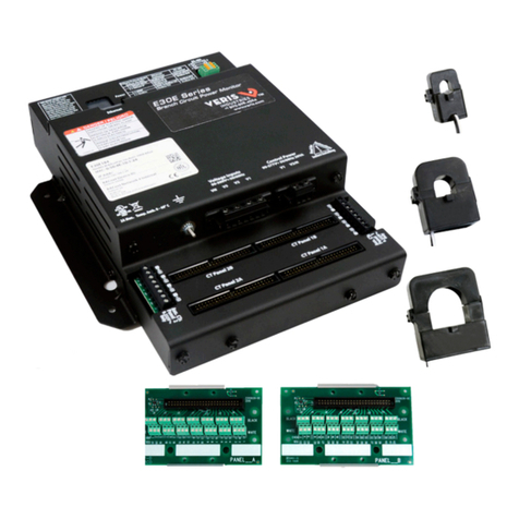
Veris Industries E30E Series User manual

Veris Industries

Veris Industries E30E Series User manual

Veris Industries Hawkeye 8025 User manual

Veris Industries

Veris Industries Hawkeye 8025 User manual

Veris Industries E30 Series User manual

Veris Industries

Veris Industries E30 Series User manual

Veris Industries E31 Series User manual

Veris Industries

Veris Industries E31 Series User manual

Veris Industries E31E84 User manual

Veris Industries

Veris Industries E31E84 User manual

Veris Industries E50C1A User manual

Veris Industries

Veris Industries E50C1A User manual
Popular Measuring Instrument manuals by other brands

Fluidwell F010-P manual

Fluidwell

Fluidwell F010-P manual

Endress+Hauser Silopilot FMM50 operating instructions

Endress+Hauser

Endress+Hauser Silopilot FMM50 operating instructions

Rosemount 2088 Reference manual

Rosemount

Rosemount 2088 Reference manual

Solinst 101D operating instructions

Solinst

Solinst 101D operating instructions

Agilent Technologies VS Series Quick reference card

Agilent Technologies

Agilent Technologies VS Series Quick reference card

THORLABS PM100 Operation manual

THORLABS

THORLABS PM100 Operation manual

Keysight Technologies MY53280000 Installation notes

Keysight Technologies

Keysight Technologies MY53280000 Installation notes

Blue-White industries F451 Series instruction manual

Blue-White industries

Blue-White industries F451 Series instruction manual

Bosch BEA 550 Original instructions

Bosch

Bosch BEA 550 Original instructions

AR DC6380M1 Operating and service manual

AR

AR DC6380M1 Operating and service manual

TFA SOUND BEE instruction manual

TFA

TFA SOUND BEE instruction manual

Akai GX-221 Operator's manual

Akai

Akai GX-221 Operator's manual

Motion Pro Motion Pro  08-0468 instructions

Motion Pro

Motion Pro Motion Pro 08-0468 instructions

Deepace KC901M user manual

Deepace

Deepace KC901M user manual

Apera Instruments SX823-B instruction manual

Apera Instruments

Apera Instruments SX823-B instruction manual

Gima 35093 Use and maintenance book

Gima

Gima 35093 Use and maintenance book

Endress+Hauser Dosimag operating instructions

Endress+Hauser

Endress+Hauser Dosimag operating instructions

Cewe Prometer 100 user manual

Cewe

Cewe Prometer 100 user manual

manuals.online logo
manuals.online logoBrands
  • About & Mission
  • Contact us
  • Privacy Policy
  • Terms and Conditions

Copyright 2025 Manuals.Online. All Rights Reserved.