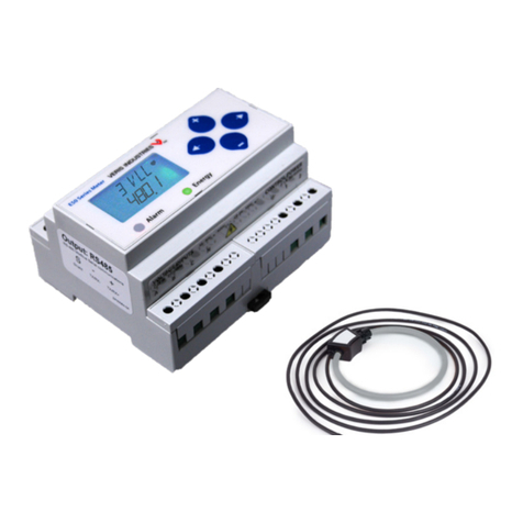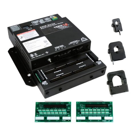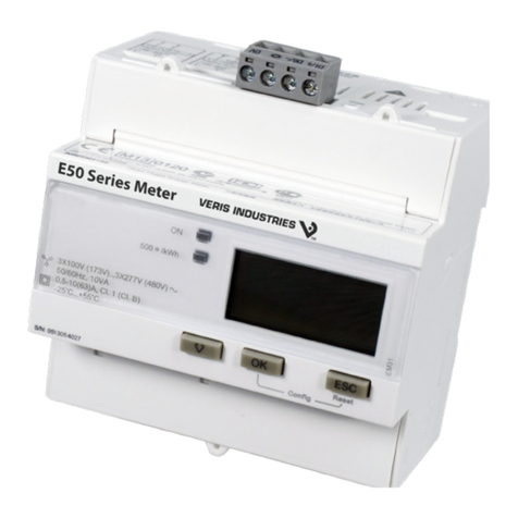
POWER MONITORING INSTALLATION GUIDE
Z205338-0
C
PAGE 1 ©2009 Veris Industries USA 800.354.8556 or +1(0)503.598.4564 / suppor[email protected] 07091Alta Labs, Enercept, Enspector, Hawkeye, Trustat, Veris, and the Veris ‘V’ logo are trademarks or registered trademarks of Veris Industries, L.L.C. in the USA and/or other countries.
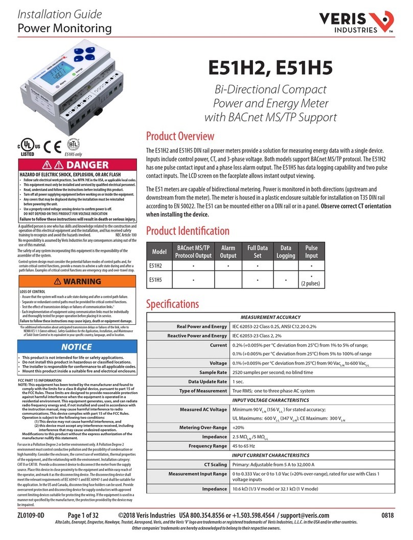
H81xx
Installer’s Specifications
Insulation Class 600VAC *
Sample Rate 1280 Hz
Internal Isolation 2500VAC
Operating Temp. Range 0° to 50°C (32° to 122°F) (<95%RH, non-condensing)
Storage Temp. Range -40°C to 70°C (-40° to 158°F)
Accuracy ±1% of reading from 2% to 100% of the CT current rating **
Power Consumption 50 VA
Voltage Tolerance:
H8150 Control Power 90 to 132VAC line-to-neutral
H8163 Control Power 90 to 300VAC line-to-neutral
Electrical Services:
H8150 120/240 VAC with neutral, 208Y/120 VAC line-to-neutral
H8163 Any service in which the phase A-N voltage is ≤300VAC and
the phase-to-phase voltage is ≤480 VAC nom. with neutral
Frequency 50/60 Hz
Pulse Output (H8163 only) N.O., Opto-Fet, 100mA@240VAC/DC
Pulse Rate (H8163 only) 0.10, 0.25, 0.50, 1.00 kWh per pulse (jumper selectable)
Pulse Width (H8163 only) 200msec closed
Phase Loss Alarm Output (H8163 only) N.O. (opens on alarm), Opto-Fet, 100mA@24VAC/DC;
Fixed threshold 25% below any other phase;
remains open while alarm persists
Safety UL 3111-1 Cat. III pollution degree 2, alt. 0-2000 meters
Protection Class NEMA 1
* Do not apply 600V class current transformers to circuits having a phase-to-phase voltage
greater than 600V without adequate additional insulation between primary conductor and
current transformers.
** Meters and current transformers are calibrated as a set. To achieve this accuracy, match the
serial numbers on the transformers and the meter at the time of installation.
Energy Meter
)";"3%0'&-&$53*$4)0$,&91-04*0/03"3$'-"4)
t 'PMMPXTBGFFMFDUSJDBMXPSLQSBDUJDFT4FF/'1"&JOUIF64"PSBQQMJDBCMFMPDBMDPEFT
t 5IJTFRVJQNFOUNVTUPOMZCFJOTUBMMFEBOETFSWJDFECZRVBMJmFEFMFDUSJDBMQFSTPOOFM
t 3FBEVOEFSTUBOEBOEGPMMPXUIFJOTUSVDUJPOTCFGPSFJOTUBMMJOHUIJTQSPEVDU
t 5VSOPõBMMQPXFSTVQQMZJOHFRVJQNFOUCFGPSFXPSLJOHPOPSJOTJEFUIFFRVJQNFOU
t 6TFBQSPQFSMZSBUFEWPMUBHFTFOTJOHEFWJDFUPDPOmSNQPXFSJTPõ
%0/05%&1&/%0/5)*4130%6$5'0370-5"(&*/%*$"5*0/
t 0OMZJOTUBMMUIJTQSPEVDUPOJOTVMBUFEDPOEVDUPST
'BJMVSFUPGPMMPXUIFTFJOTUSVDUJPOTXJMMSFTVMUJOEFBUIPSTFSJPVTJOKVSZ
%"/(&3
/05*$&
t 5IJTQSPEVDUJTOPUJOUFOEFEGPSMJGFPSTBGFUZBQQMJDBUJPOT
t %POPUJOTUBMMUIJTQSPEVDUJOIB[BSEPVTPSDMBTTJmFEMPDBUJPOT
t 5IFJOTUBMMFSJTSFTQPOTJCMFGPSDPOGPSNBODFUPBMMBQQMJDBCMFDPEFT
t .PVOUUIJTQSPEVDUJOTJEFBTVJUBCMFmSFBOEFMFDUSJDBMFODMPTVSF
'$$1"35*/'03."5*0/
/05&5IJTFRVJQNFOUIBTCFFOUFTUFECZUIFNBOVGBDUVSFSBOEGPVOE
UPDPNQMZXJUIUIFMJNJUTGPSBDMBTT"EJHJUBMEFWJDFQVSTVBOUUPQBSU
PGUIF'$$3VMFT5IFTFMJNJUTBSFEFTJHOFEUPQSPWJEFSFBTPOBCMF
QSPUFDUJPOBHBJOTUIBSNGVMJOUFSGFSFODFXIFOUIFFRVJQNFOUJT
PQFSBUFEJOBDPNNFSDJBMFOWJSPONFOU5IJTFRVJQNFOUHFOFSBUFT
VTFTBOEDBOSBEJBUFSBEJPGSFRVFODZFOFSHZBOEJGOPUJOTUBMMFEBOE
VTFEJOBDDPSEBODFXJUIUIFJOTUSVDUJPONBOVBMNBZDBVTFIBSNGVM
JOUFSGFSFODFUPSBEJPDPNNVOJDBUJPOT0QFSBUJPOPGUIJTFRVJQNFOUJO
BSFTJEFOUJBMBSFBJTMJLFMZUPDBVTFIBSNGVMJOUFSGFSFODFJOXIJDIDBTF
UIFVTFSXJMMCFSFRVJSFEUPDPSSFDUUIFJOUFSGFSFODFBUIJTPXOFYQFOTF
.PEJmDBUJPOTUPUIJTQSPEVDUXJUIPVUUIFFYQSFTTBVUIPSJ[BUJPOPG
7FSJT*OEVTUSJFTOVMMJGZUIJTTUBUFNFOU
quick install
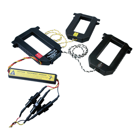
Verify that serial numbers on meter and current transformers match.1.
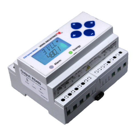
Mount the meter housing.2.
Attach current transformer(s) to the conductor.3.
Connect voltage leads.4.
Use color coding to connect current transformer leads to the input terminals and5.
voltage leads to phase conductors (e.g. red to red).
Connect the Pulse and Phase Loss output terminals to the controller (H8163 only).6.
Set the backlight and display data jumpers as desired.7.
Set the Pulse Rate selection switch as desired (H8163 only).8.
Secure the cover.9.
Apply power to the meter.10.
H81xx
AH06 (optional
mounting bracket)
