Veris Industries HO Series User manual

Installation Guide
Humidity
Z201382-0Y Page 1 of 5 ©2015 Veris Industries USA 800.354.8556 or +1.503.598.4564 / suppor[email protected] 0315
Alta Labs, Enercept, Enspector, Hawkeye, Trustat, Aerospond, Veris, and the Veris ‘V’ logo are trademarks or registered trademarks of Veris Industries, L.L.C. in the USA and/or other countries.
Other companies’ trademarks are hereby acknowledged to belong to their respective owners.
TM
NOTICE
• This product is not intended for life or safety applications.
• Do not install this product in hazardous or classied locations.
•
Read and understand the instructions before installing this product.
• Turn o all power supplying equipment before working on it.
• The installer is responsible for conformance to all applicable codes.
No responsibility is assumed byVeris Industries for any consequences arising out of the
use of this material.
Product Identification
Product Overview
The HO Series outdoor humidity sensors provide high accuracy humidity monitoring with a fully replaceable HS
element for easy field maintenance. NIST certified accuracy and temperature sensing capability are available.
HO Series
Digital RH and RH/T Transmiers
T = Temp
X = No Temp
(Stop here)
US or EU Temp.
Sensor Type
Accuracy NIST
S = Standard
C = CE
B = 100R Platinum, RTD
C = 1k Platinum, RTD
D = 10k T2, Thermistor
E = 2.2k, Thermistor
F = 3k, Thermistor
G = 10k CPC, Thermistor
H = 10k T3, Thermistor
J = 10k Dale, Thermistor
K = 10k with 11k shunt, Thermistor
M = 20k NTC, Thermistor
N = 1800 ohm TAC, Thermistor
Q = 1uA/˚C, Linitemp
R = 10k US, Thermistor
S = 10k 3A 221, Thermistor
T = 100k, Thermistor
U = 20k “D”, Thermistor
Output
M = 4-20mA
V = 0-5V/0-10VDC
2 = 2%
3 = 3%
5 = 5%
HO
Sensor Type Range
Temp Cert
Blank = None
1 =1pt Cal
2 = 2pt Cal
OPTION
Humidity Transmitter Combination Humidity RTD/Thermistor Combination
Blank = None
1 =1pt Cal
2 = 2pt Cal
A
= Transmitter
N = NIST
X = None
Temp Cert
OPTION
1 = -40° to 50°C
(-40° to 122°F)
2 = 0° to 50°C
(32° to 122°F)

Z201382-0Y Page 2 of 5 ©2015 Veris Industries USA 800.354.8556 or +1.503.598.4564 / suppor[email protected] 0315
Alta Labs, Enercept, Enspector, Hawkeye, Trustat, Aerospond, Veris, and the Veris ‘V’ logo are trademarks or registered trademarks of Veris Industries, L.L.C. in the USA and/or other countries.
Other companies’ trademarks are hereby acknowledged to belong to their respective owners.
Installation Guide
Humidity
HOSeries TM
Dimensions
Wiring
Specifications HS Element Digitally profiled thin-film capacitive (32-bit mathematics)
U.S. Patent No. 5,844,138
Accuracy @ 25°C from 10-80% RH* 2%, 3%, or 5% (specify); Multi-point calibration, NIST traceable
Reset Rate** 24 hours
Stability ±1% @ 20°C (68°F) annually, for two years
Operating Humidity Range 0 to 100% RH
Operating Temperature Range -40° to 50°C (-40° to 122°F)
Hysteresis 1.5% t ypical
Linearity Included in Accuracy spec.
Temperature Coefficient ±0.1% RH/°C above or below 25°C (typical)
Analog Output 4-20mA version: 2-wire, polarity insensitive (clipped and capped);
0-5V/0-10V versions: 3 wire; observe polarity
Scaling 0–100% R H
Input Power*** 4-20mA version: loop powered 12-30VDC only, 30mA max.;
0-5V/0-10V versions: 12-30VDC/24VDC, 15mA max.
Optional Temperature Transmitter Output Digital, 4-20mA (clipped and capped) or 0-5V/0-10V output;
accuracy ±1.3°C (±2.3°F) typical
EMC Conformance - CE Option Low Voltage Directive 2006/95/EC and EMC Directive 2004/108/
EC
Limited Warranty 5 years
* Specified accuracy with 24VDC supplied power with rising humidity.
** Reset Rate is the time required to recover to 50% RH after exposure to 90% RH for 24 hours.
*** One side of transformer secondary is connected to signal common. Isolation transformer or dedicated power
supply may be required.
RTD thermistors are not compensated for internal heating of product.
To conform to EMC standards, shielded cabling and technical information is available from factory upon request or is
available on our website: www.veris.com.
EMC Special Note: Connect this product to a DC distribution network or an AC/DC power adaptor with proper surge
protection (EN 61000-6-1 specification requirements).
2.3"
(58 mm)
4.6"
(116 mm)
0.7"
(18 mm)
12.7"
(323 mm)
2.8"
(72 mm)
2.7"
(69 mm)
0-5V/0-10V Versions
NOTE: For 24 VAC transformer powered applications, one side of transformer secondary is con-
nected to common. Isolation transformer or dedicated power supply may be required.
POWER SUPPLY
24VDC
BLK
RED
BLUE 0-10V HUMIDITY
ORANGE 0-10V TEMP
GREEN 0-5V HUMIDITY
YELLOW 0-5V TEMP
–
+
8.45"
(215 mm)

Z201382-0Y Page 3 of 5 ©2015 Veris Industries USA 800.354.8556 or +1.503.598.4564 / suppor[email protected] 0315
Alta Labs, Enercept, Enspector, Hawkeye, Trustat, Aerospond, Veris, and the Veris ‘V’ logo are trademarks or registered trademarks of Veris Industries, L.L.C. in the USA and/or other countries.
Other companies’ trademarks are hereby acknowledged to belong to their respective owners.
Installation Guide
Humidity
HOSeries TM
Wiring (Cont.) 0-5V/0-10V Versions
RTD/Thermistor, 0-5V/0-10V Versions
4-20mA Versions
RTD/Thermistor, 4-20mA Versions
NOTE: For 24 VAC transformer powered applications, one side of transformer secondary is con-
nected to common. Isolation transformer or dedicated power supply may be required.
POWER SUPPLY
24 VDC only
DIGITAL CONTROL
Temperature
4-20mA Return
(optional)
Humidity
4-20mA Return
BLUE
HUMIDITY
BLUE
HUMIDITY
White/Gray 0-1V
Test Leads for use
with voltmeter
ORANGE
TEMP
ORANGE
TEMP
+
–
–
POWER SUPPLY
24VDC
BLK
RED
BLUE 0-10V HUMIDITY
ORANGE 0-10V TEMP
GREEN 0-5V HUMIDITY
YELLOW 0-5V TEMP
–
+
8.45"
(215 mm)
POWER SUPPLY
12 to 24VDC
DIGITAL CONTROL
Temperature
4-20mA Return
(optional)
Humidity
4-20mA Return
BLUE
HUMIDITY
BLUE
HUMIDITY
White/Gray 0-1V
Test Leads for use
with voltmeter
ORANGE
Thermistor ORANGE
Thermistor
+
–
–
POWER SUPPLY
12 to 24VDC/24VAC
BLK
RED
BLUE 0-10V HUMIDITY
GREEN 0-5V HUMIDITY
ORANGE THERMISTOR
ORANGE THERMISTOR
–
+

Z201382-0Y Page 4 of 5 ©2015 Veris Industries USA 800.354.8556 or +1.503.598.4564 / suppor[email protected] 0315
Alta Labs, Enercept, Enspector, Hawkeye, Trustat, Aerospond, Veris, and the Veris ‘V’ logo are trademarks or registered trademarks of Veris Industries, L.L.C. in the USA and/or other countries.
Other companies’ trademarks are hereby acknowledged to belong to their respective owners.
Installation Guide
Humidity
HOSeries TM
Test Points and
Setup Verification
Calibration-Free
Sensor
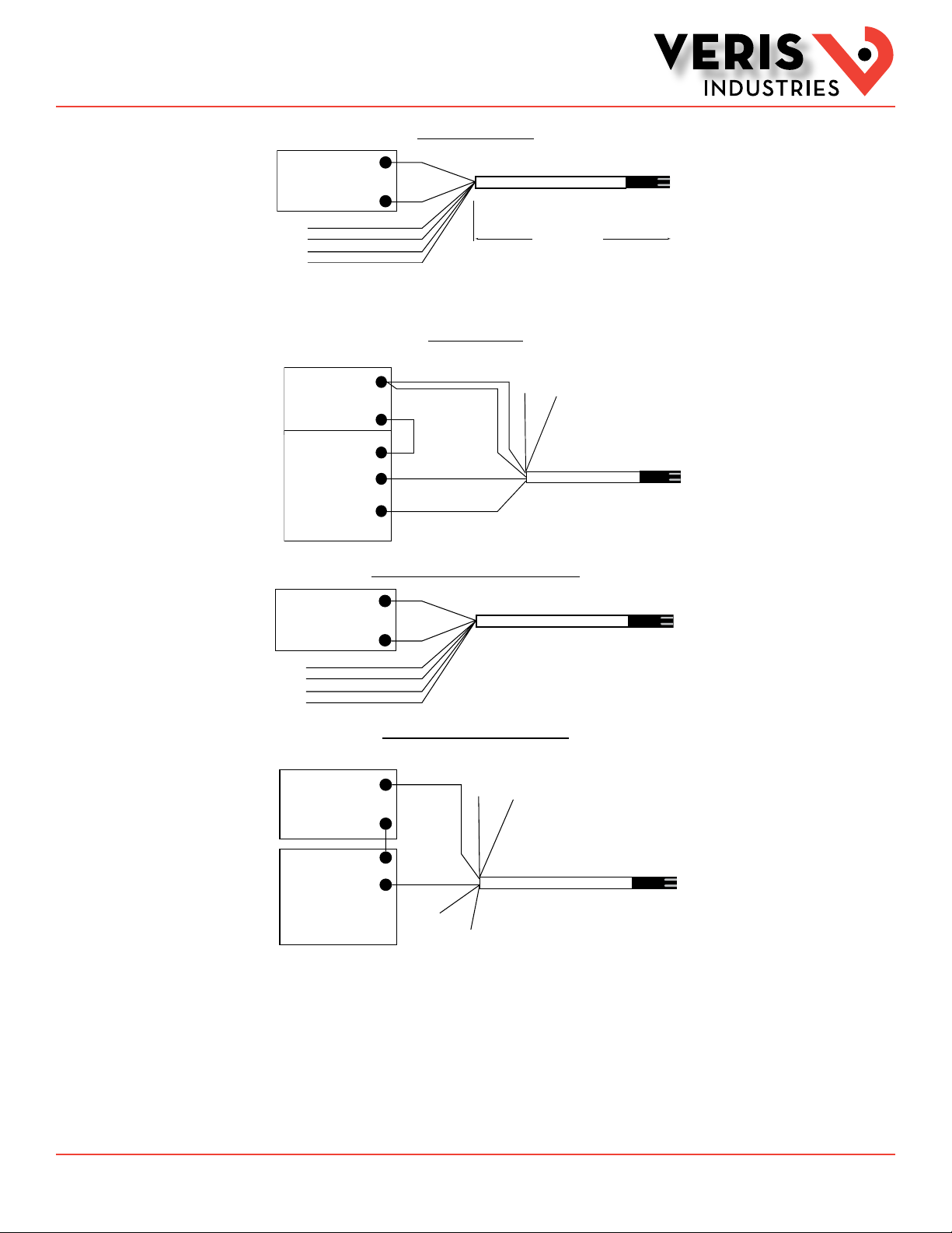
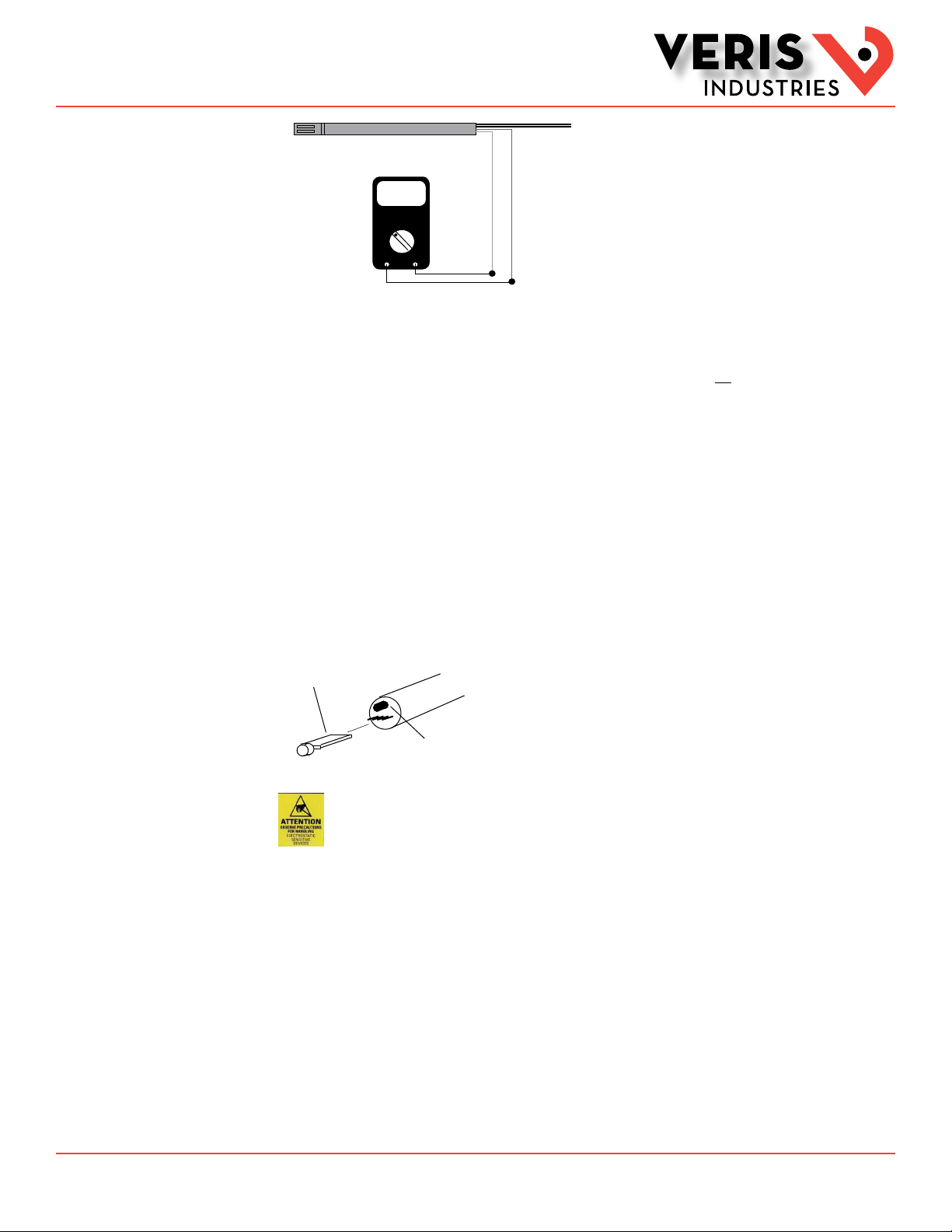
For 4-20 mA versions: Test leads output 0-1VDC corresponding to 0 to 100% RH sensor reading. For example, a 0.42 VDC output
on test points equals 42% RH sensor reading. These test points also provide an output that verifies mother board accuracy when
the HS element is removed. CONNECT TEST POINT LEADS TO VOLTMETER ONLY. This output is not suitable for connection to a DDC
panel.
To check motherboard functionality using the test leads, remove sensor element. 1.0 VDC reading verifies motherboard
functionality.
To verify sensor accuracy, de-power unit and insert a replacement HS element. Repower unit and compare readings to original
sensor. For example, if test points read 0.40VDC (40% RH) with original sensor, and 0.45VDC (45% RH) with new replacement
sensor, the original sensor is 5% off specification. This method of ensuring accuracy offers more precision than using slings or
other devices, and it eliminates the need to manually adjust sensors to an unstable standard.
Note: Temperature, body sweat, and breath effect humidity. Ensure that conditions are stable to evaluate performance.
Filter may be washed using warm water and soft brush. Do not attempt to scrub HS element.
For 0-5V/0-10V versions, use output as test point and scale accordingly.
Test leads and voltmeter
verify accuracy
and simplify DDC
programming
1VDC
0.42
WHITE (+)
GREY(--)
Voltmeter shows reading of 42% RH
Replaceable HS Element
Optional
Temp sensor
The microprocessor-profiled
capacitive HS element can be
replaced in the field without
calibration.
Observe precautions for handling static sensitive
devices to avoid damage to the circuitry that
is not covered under the factory warranty.
To replace HS Element
1. Disconnect power to the unit.
2. Remove probe from junction box by loosening black swage nut and sliding out.
3. Removed HS element by unscrewing probe filter tip and gently pulling sensor board from jack. Do not attempt to remove black
temperature sensor next to board.
4. Install new HS element, observing orientation such that filter tip can be reinstalled.
Replacement HS Element Ordering Information
HS2xx Replacement 2% HS Element, Duct
HS3xx Replacement 3% HS Element, Duct

Z201382-0Y Page 5 of 5 ©2015 Veris Industries USA 800.354.8556 or +1.503.598.4564 / suppor[email protected] 0315
Alta Labs, Enercept, Enspector, Hawkeye, Trustat, Aerospond, Veris, and the Veris ‘V’ logo are trademarks or registered trademarks of Veris Industries, L.L.C. in the USA and/or other countries.
Other companies’ trademarks are hereby acknowledged to belong to their respective owners.
Installation Guide
Humidity
HOSeries TM
Calibration-Free
Sensor (Cont.)
Troubleshooting
HS5xx Replacement 5% HS Element, Duct
HS1Nx Replacement 1% HS NIST Element, Duct
HS2Nx Replacement 2% HS NIST Element, Duct
Replacement filters are provided with all elements. Order appropriate element accuracy to match motherboard accuracy for
compatability.
Problem Solution
Filter tip does not fit on probe HS element is backwards; reverse element.
Unit reads approx. 4.5mA HS element is backwards; reverse element.
Unit reads 100% with new replacement sensor Unit must be unpowered when installing a new sensor; interrupt sensor power to
restart.
Accuracy appears incorrect · Remove HS element while powered and verify output goes to full scale.
· Verify voltage test leads on 4-20mA models corresponds to the 4-20mA output.
Table of contents
Other Veris Industries Transmitter manuals