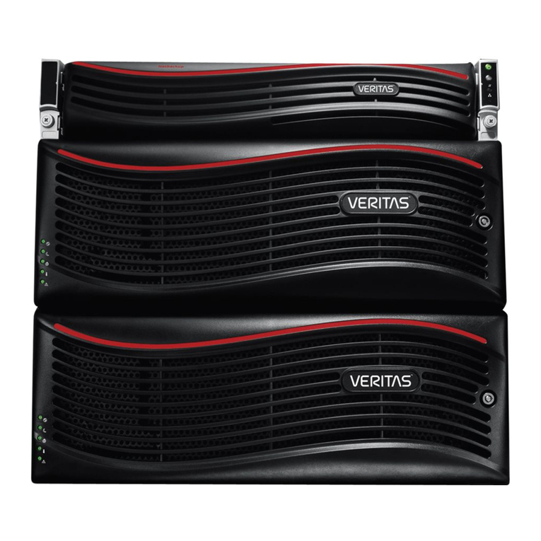
VERITAS NetBackup 5240 Manual

NetBackup Appliance
Hardware Installation Guide
Release 2.7.3
NetBackup 5240
Document Revision 1

NetBackup™ 5240 Appliance Hardware Installation
Guide
Documentation version: 2.7.3
Legal Notice
Copyright © 2016 Veritas Technologies LLC. All rights reserved.
Veritas and the Veritas Logo are trademarks or registered trademarks of Veritas Technologies
LLC or its affiliates in the U.S. and other countries. Other names may be trademarks of their
respective owners.
This product may contain third party software for which Veritas is required to provide attribution
to the third party (“Third Party Programs”). Some of the Third Party Programs are available
under open source or free software licenses. The License Agreement accompanying the
Software does not alter any rights or obligations you may have under those open source or
free software licenses. Refer to the third party legal notices document accompanying this
Veritas product or available at:
https://www.veritas.com/about/legal/license-agreements
The product described in this document is distributed under licenses restricting its use, copying,
distribution, and decompilation/reverse engineering. No part of this document may be
reproduced in any form by any means without prior written authorization of Veritas Technologies
LLC and its licensors, if any.
THE DOCUMENTATION IS PROVIDED "AS IS" AND ALL EXPRESS OR IMPLIED
CONDITIONS, REPRESENTATIONS AND WARRANTIES, INCLUDING ANY IMPLIED
WARRANTY OF MERCHANTABILITY, FITNESS FOR A PARTICULAR PURPOSE OR
NON-INFRINGEMENT, ARE DISCLAIMED, EXCEPT TO THE EXTENT THAT SUCH
DISCLAIMERS ARE HELD TO BE LEGALLY INVALID. VERITAS TECHNOLOGIES LLC
SHALL NOT BE LIABLE FOR INCIDENTAL OR CONSEQUENTIAL DAMAGES IN
CONNECTION WITH THE FURNISHING, PERFORMANCE, OR USE OF THIS
DOCUMENTATION. THE INFORMATION CONTAINED IN THIS DOCUMENTATION IS
SUBJECT TO CHANGE WITHOUT NOTICE.
The Licensed Software and Documentation are deemed to be commercial computer software
as defined in FAR 12.212 and subject to restricted rights as defined in FAR Section 52.227-19
"Commercial Computer Software - Restricted Rights" and DFARS 227.7202, et seq.
"Commercial Computer Software and Commercial Computer Software Documentation," as
applicable, and any successor regulations, whether delivered by Veritas as on premises or
hosted services. Any use, modification, reproduction release, performance, display or disclosure
of the Licensed Software and Documentation by the U.S. Government shall be solely in
accordance with the terms of this Agreement.
Veritas Technologies LLC
500 E Middlefield Road
Mountain View, CA 94043
http://www.veritas.com
Technical Support
Technical Support maintains support centers globally. All support services will be delivered
in accordance with your support agreement and the then-current enterprise technical support
policies. For information about our support offerings and how to contact Technical Support,
visit our website:
https://www.veritas.com/support
You can manage your Veritas account information at the following URL:
https://my.veritas.com
If you have questions regarding an existing support agreement, please email the support
agreement administration team for your region as follows:
[email protected]Japan
Documentation
Make sure that you have the current version of the documentation. Each document displays
the date of the last update on page 2. The latest documentation is available on the Veritas
website:
https://sort.veritas.com/documents
Documentation feedback
Your feedback is important to us. Suggest improvements or report errors or omissions to the
documentation. Include the document title, document version, chapter title, and section title
of the text on which you are reporting. Send feedback to:
You can also see documentation information or ask a question on the Veritas community site:
http://www.veritas.com/community/
Veritas Services and Operations Readiness Tools (SORT)
Veritas Services and Operations Readiness Tools (SORT) is a website that provides information
and tools to automate and simplify certain time-consuming administrative tasks. Depending
on the product, SORT helps you prepare for installations and upgrades, identify risks in your
datacenters, and improve operational efficiency. To see what services and tools SORT provides
for your product, see the data sheet:
https://sort.veritas.com/data/support/SORT_Data_Sheet.pdf


Chapter 1 Hardware overview ............................................................. 7
About the appliance and the storage shelves ....................................... 7
Appliance disk drives ...................................................................... 8
Appliance control panel ................................................................... 8
Appliance rear panel ....................................................................... 9
Storage shelf disk drives ................................................................ 10
Storage shelf control panel ............................................................. 11
Storage shelf rear panel ................................................................. 12
Cables ....................................................................................... 12
About IPMI configuration ................................................................ 13
Product documentation .................................................................. 14
Chapter 2 Preinstallation requirements .......................................... 15
Customer-provided environment and supplies .................................... 15
Storage shelf shipping container contents .......................................... 16
Appliance shipping container contents .............................................. 16
Determining rack locations ............................................................. 17
Best practices for rack installation .................................................... 18
Heat dissipation ........................................................................... 19
Determining SAS-3 cable length ...................................................... 19
Prerequisites for IPMI configuration .................................................. 20
Chapter 3 Installation procedures ..................................................... 23
Installing the storage shelf rack rails ................................................. 23
Installing the storage shelf into a rack ............................................... 25
Installing the appliance rack rails ..................................................... 26
Installing the appliance into a rack ................................................... 31
Understanding appliance and storage shelf connections ....................... 34
Connecting a 4TB appliance to one storage shelf ................................ 37
Connecting a 4TB appliance to more than one storage shelf ................. 39
Connecting the network cables ........................................................ 47
Connecting the power cords ........................................................... 48
Turning on the hardware and verifying operation ................................. 49
Configuring the IPMI from the NetBackup Appliance Shell Menu ............ 57
Contents

Accessing and using the Veritas Remote Management interface ............ 62
Appendix A Adding one or more storage shelves to an
operating 4TB appliance that does not have
any storage shelves .................................................... 67
Overview .................................................................................... 68
Preparing the 4TB appliance ........................................................... 69
Removing the appliance cover ........................................................ 70
Installing the External Storage Kit components ................................... 71
Reinstalling the appliance into the rack ............................................. 85
Storage shelf rack requirements ...................................................... 86
Determining rack locations ............................................................. 86
Installing the storage shelf rails ....................................................... 88
Installing the storage shelf or shelves into a rack ................................. 90
Understanding appliance and storage shelf connections ....................... 91
Connecting one storage shelf to an appliance .................................... 95
Connecting two storage shelves to an appliance ................................. 98
Connecting three storage shelves to an appliance ............................. 101
Connecting four storage shelves to an appliance ............................... 107
Connecting the network cables ...................................................... 113
Connecting the power cords ......................................................... 114
Turning on the hardware and verifying operation ............................... 115
Appendix B Adding storage shelves to an operating 4TB
appliance that has at least one storage shelf
attached ........................................................................ 125
Overview .................................................................................. 125
Additional storage shelf scenarios for a 4TB appliance ....................... 126
Installing storage shelves ............................................................. 126
Recabling ................................................................................. 126
Appendix C Adding the disk space of additional storage
shelves .......................................................................... 141
Adding the disk space of additional storage shelves from the NetBackup
Appliance Web Console ......................................................... 141
Adding the disk space of additional storage shelves from the NetBackup
Appliance Shell Menu ............................................................ 142
Index .................................................................................................................. 145
Contents6

Hardware overview
This chapter includes the following topics:
■About the appliance and the storage shelves
■Appliance disk drives
■Appliance control panel
■Appliance rear panel
■Storage shelf disk drives
■Storage shelf control panel
■Storage shelf rear panel
■Cables
■About IPMI configuration
■Product documentation
About the appliance and the storage shelves
The NetBackup 5240 appliance and storage shelves provide storage capacity in
several configurations. You can use the appliance by itself to achieve 4TB, 14TB,
or 27TB of useable capacity. You can add storage shelves to a 4TB appliance to
further increase the storage capacity.
Refer to the NetBackup 5240 Product Description at the following site for details.
NetBackup Appliance Documentation
1
Chapter

Appliance disk drives
The front panel of the appliance contains 12 disk drives.
Slot designations are as follows. Do not rearrange the disk drives from the factory
configuration.
Table 1-1 NetBackup 5240 Appliance disk drive slots
Disk drive roleAppliance storage
capacity
Disk drive
size
RAID
configuration
Slot
Boot/swapN/A1TBRAID 10, 1
Log filesN/A1TBRAID 12, 3
User storage data4TB, 14TB, 27TB1TB, 3TB, 6TBRAID 64 - 10
Hot spareN/A1TB, 3TB, 6TBRAID 611
Appliance control panel
The front panel of the NetBackup 5240 Appliance includes a small panel that is
attached to the right side of the device.
Hardware overview
Appliance disk drives
8

Table 1-2 Appliance control panel
DescriptionComponentNumber
The system ID LED identifies the system for
maintenance.
System ID with integrated
LED
1
When the NMI button is depressed, the appliance
goes into a halt state, and issues a non-maskable
interrupt (NMI). This feature is useful when you
perform diagnostics for a given issue where a memory
dump is necessary to help determine the cause of
the problem. To prevent an inadvertent system halt,
the NMI button is located behind the front control
panel faceplate. It is only accessible with the use of
a small tipped tool, such
NMI button (recessed, a
tool is required for use)
2
NIC-1 represents the network interface controller 1.
When network links are detected on the controllers,
the LEDs are activated and remain on. The LEDs
blink when network activity occurs. The amount of
network activity determines the rate of blinking.
NIC-1 Activity LED3
The System Cold Reset button restarts and
re-initializes the appliance.
System Cold Reset
Button (recessed, a tool
is required for use on
non-storage models)
4
The System Status LED uses the colors green and
amber to display the health of the appliance.
System Status LED5
The Power/Sleep button turns off the appliance or
turns on the appliance.
Power/Sleep button with
integrated LED
6
The drive activity LED indicates drive activity from
the on-board hard disk controllers.
Hard drive Activity LED7
NIC-2 represents the network interface controller 2.
When network links are detected on the controllers,
the LEDs are activated and remain on. The LEDs
blink when network activity occurs. The amount of
network activity determines the rate of blinking.
NIC-2 Activity LED8
Appliance rear panel
The rear panel of the appliance contains several default ports that are embedded.
Three PCIe riser assemblies support various configurations.
9Hardware overview
Appliance rear panel

The three PCIe riser assemblies outlined red are numbered, 1, 2, and 3 from right
to left. Slots 1 through 8 are shown in the risers.
The following list describes the numbered ports.
1. Two copper, RJ45, 10Gb Ethernet* ports; NIC5/eth4 and NIC 6/eth5, left to
right
2. VGA port
3. 3 USB ports
4. IPMI, remote management, port
5. Four copper, RJ45, 1Gb Ethernet* ports, NIC1/eth0, NIC2/eth1, NIC3/eth2,
and NIC4/eth3, left to right
6. Riser Assembly 2, Slot 1, reserved for the RAID PCIe card that is required with
one or more storage shelves
7. Riser Assembly 3, Slot 7, reserved for the SAS RAID HBA card that provides
RAID1 support for the appliance storage disk drives
8. Two slots that are not used at this time
Note: * The embedded Ethernet ports are copper. PCIe Ethernet ports are fibre.
You cannot bond the copper ports and the fibre ports to each other.
Refer to the Veritas NetBackup 5240 Appliance Product Description at the
NetBackup Appliance Documentation page for optional port configurations.
Storage shelf disk drives
The NetBackup 5240 Storage Shelf is a 2U enclosure that contains 12 disk drives.
Hardware overview
Storage shelf disk drives
10

Disk drive carriers in the storage shelf are locked by default. If you need to replace
a locked disk drive use a screwdriver with a T10 bit to unlock each carrier.
The lock is located on the left side of each carrier.
Storage shelf control panel
The left, front, of the storage shelf contains the system control panel.
Components of the control panel include the following.
1. The Input switch enables you to set the Unit Identification display.
2. The Power On/Standby LED is amber when only standby power is available.
The LED is green when system power is available.
11Hardware overview
Storage shelf control panel

3. The Module Fault LED is on when there is a system hardware fault. A Power
Cooling Module (PCM) or an I/O module may be at fault.
4. The Logical Status LED shows a change of status or a fault, typically associated
with the shelf's disk drives. This LED also indicates an issue with an internal
RAID controller or external RAID controller, or with a host bus adapter.
5. The Unit Identification Display provides information to assist in the configuration
of multiple storage shelves.
Storage shelf rear panel
The rear panel of the storage shelf contains two main components; two Power
Cooling Modules (PCMs) and two I/O Module canisters.
The PCMs, located on the left and the right sides of the storage shelf, contain fans.
The I/O module canisters are located in the center of the rear panel, one above the
other. Each I/O module contains three SAS-3 ports; A, B, and C. The SAS ports
connect the I/O modules to the appliance and to other storage shelves. Note that
the port labels are reversed on the bottom canister. Port C is not used at this time.
The PCMs and the I/O modules include LEDs.
Cables
Two power cables are shipped with each appliance and each storage shelf.
1m SAS-3 cables are shipped with each storage shelf. The one-meter cables are
sufficient when the recommended cabling scheme is followed. 3m SAS-3 cables
are available separately in case of need.
Hardware overview
Storage shelf rear panel
12

Use the top down, bottom up method to connect storage shelves to the appliance.
The general scheme follows.
■The appliance is connected to the first storage shelf with one SAS-3 cable.
■One cable connects the first storage shelf to the next shelf.
■Subsequent storage shelves are connected until the last storage shelf is
connected.
■The last storage shelf is connected to the appliance with one cable.
■The last storage shelf is also connected to the next, highest, storage shelf.
■The storage shelves are connected until the shelf closest to the appliance is
connected.
About IPMI configuration
The Intelligent Platform Management Interface (or IPMI) provides management and
monitoring capabilities independently of the host system's CPU, firmware, and
operating system. You can configure the IPMI sub-system for your appliances. You
can use the remote management port, located on the rear panel of the appliance,
to connect to the IPMI sub-system.
The following figure shows the remote management port (or the IPMI port) on the
rear panel of a NetBackup 5240 appliance:
IPMI
The IPMI is beneficial after an unexpected power outage shuts down the connected
system. In case the appliance is not accessible after the power is restored, you can
use a laptop or desktop computer to access the appliance remotely by using a
network connection to the hardware rather than to an operating system or login
13Hardware overview
About IPMI configuration

shell. This enables you to control and monitor the appliance even if it is powered
down, unresponsive, or without any operating system.
The following diagram illustrates how IPMI works:
How does IPMI work?
When an appliance is
powered off or cannot be
accessed using the
network interface
Remote Management
Port
Out of band management using IPMI
Remote Management Console
Some of the main uses of IPMI are the following:
■Manage an appliance that is powered off or unresponsive. Using the IPMI, you
can power on, power off, or restart the appliance from a remote location.
■Provides out-of-band management and help manage situations where local
physical access to the appliance is not possible or preferred like branch offices
and remote data center.
■In case the appliance is not accessible using regular network interfaces, you
can access the NetBackup Appliance Shell Menu remotely using IPMI.
■Reimage the appliance from the IPMI interface by using ISO redirection.
■Monitor hardware health of the appliance from a remote location.
■Avoid messy cabling and hardware like keyboard, monitor, and mouse (KVM)
solutions.
Product documentation
Additional documentation is available at the following site.
NetBackup Appliance Documentation page
Hardware overview
Product documentation
14

Preinstallation
requirements
This chapter includes the following topics:
■Customer-provided environment and supplies
■Storage shelf shipping container contents
■Appliance shipping container contents
■Determining rack locations
■Best practices for rack installation
■Heat dissipation
■Determining SAS-3 cable length
■Prerequisites for IPMI configuration
Customer-provided environment and supplies
For best ventilation, the rack cabinet:
■Should be at least 100 cm (4 feet) from walls
■Should have at least 100 cm (4 feet) from other cabinets on the front and back
of the appliance and the storage shelves
Data centers with two foot spaces in the front and in the back of the appliances are
acceptable with proper cooling and ventilation.
Refer to the following section for more details.
Heat dissipation
2
Chapter

The following describes the necessary personnel and equipment that are needed
at the installation site:
■At least one person or a mechanical lift to move the appliance and the storage
shelves.
■Ethernet and Fibre Channel (FC) cables to connect the appliance to your
corporate network.
■A USB-keyboard and a monitor to connect to the appliance.
■A 19-inch rack with dual Power Distribution Units (PDUs) with 120VAC or
220VAC power supplies.
Storage shelf shipping container contents
The appliance and each storage shelf are shipped in separate containers. Each
container includes other boxes and contents. The disk drives are installed into the
appliance and the storage shelf at the factory.
The following items ship within the storage shelf box.
■Open Me First box, containing
■Installation flip cards
■Deployment plan that provides basic information and links to detailed
information
■Rack mounting template
■Installation poster
■Cabling poster
■Rack rails
■Two SAS-3 cables
■Two power cords
■Bezel
Appliance shipping container contents
The appliance and each storage shelf are shipped in separate containers. Each
container includes other boxes and contents. The disk drives are installed into the
appliance and the storage shelf at the factory.
The following items ship within the appliance box.
Preinstallation requirements
Storage shelf shipping container contents
16

■Open Me First box, containing:
■Installation flip cards
■Deployment plan that provides basic information, and links to detailed
information
■Rack mounting templates
■Screwdriver and cable straps
■Installation poster
■Cabling poster
■Envelope containing the following:
■USB drive(s) with factory reset files
■Warranty and license information
■Accessory box containing rack rails
■Two power cables
■Bezel
Determining rack locations
The appliance and the storage shelves are both two rack units (2RU) high. To help
you identify RU spacing, many rack manufacturers typically use a system of lines
and sequential numbers starting at the bottom of the rack. The front and the rear
of the rack are marked the same to ensure that the rails are installed straight and
level. One RU has three holes. The holes for one RU are typically marked with a
line below the bottom hole and another line above the top hole.
Use the rack templates to determine the mounting locations for all devices.
17Preinstallation requirements
Determining rack locations

To determine rack locations for the hardware
1Determine the total number of rack units (RUs) that you need as follows:
■The appliance and the storage shelves each require 2RUs of height in the
rack.
■An appliance and four storage shelves require a total of ten RUs.
2Use the rack templates that are provided with the hardware to determine RU
locations. The appliance and the storage shelf templates show the front and
rear of each device in a rack.
3Record the rack positions to help you locate them easily when mounting the
hardware.
Best practices for rack installation
Prepare for the hardware installation by following these recommendations.
■The storage shelves are heavier than the appliance and should be installed as
close to the bottom of the rack as possible.
■Determine device order and cabling limits.
■Be aware of the depth of the guide rails and the devices. Ensure that the distance
between cabinet posts accommodates the rails, devices, cables, and extending
ears.
■Physically hold a SAS cable between the intended locations for the appliance
and the last storage shelf. Visually confirm that the cable is long enough.
Preinstallation requirements
Best practices for rack installation
18

Heat dissipation
Air flows from the front of each unit and exits from the rear of each unit. You can
install the optional bezel without disruption to the airflow.
For best ventilation, the rack cabinet should:
■Be at least 100 cm (4 feet) from walls.
■Be at least 100 cm (4 feet) from other cabinets on the front and back of the
appliance and the storage shelves.
Note: Data centers with two-foot spaces in the front and in the back of the appliances
are acceptable with proper cooling and ventilation.
Veritas provides the following requirements to ensure sufficient cooling.
■Veritas requires that you install the system in a National Engineering
Manufacturer's Association (NEMA)-certified or equivalent rack.
■A minimum of 3 inches (7.6 cm) of space must be between the front of an
appliance and the cabinet door or other air block.
■A minimum of 6 inches (15.2 cm) of space must be between the rear of an
appliance and the cabinet rear or other air block.
■A minimum of 1 inch (2.5 cm) of space must be between the front of a storage
shelf and the cabinet door or other air block.
■A minimum of 2 inches (5.0 cm) of space must be between the rear of a storage
shelf and the cabinet rear or other air block.
■Veritas strongly recommends that customers insure the appliance and the
storage shelves have sufficient cooling, especially when installed in a fully
enclosed rack.
Refer to the NetBackup 5240 Appliance Product Description for specifications about
temperature and cooling.
NetBackup Appliance documentation
Determining SAS-3 cable length
Before you install and connect the hardware, be sure to verify that you have the
correct length of the SAS-3 cables for your setup.
Each rack unit (RU) is 44.50 mm (1.752 inches) in height. The NetBackup 5240
Appliance and the NetBackup 5240 Storage Shelf are both 2RU high.
19Preinstallation requirements
Heat dissipation

Each SAS-3 cable is 1 meter (3.28 feet) long. The 1-meter cable is long enough to
connect an appliance to the fourth storage shelf when the recommended
configuration is used. A 3 meter (9.84 feet) SAS-3 cable is available separately in
case your rack arrangement requires more length. Contact Veritas Technical
Support, if needed.
Prerequisites for IPMI configuration
Verify the following configuration prerequisites:
■The remote management port can auto-negotiate its link speed of up to 1 Gbps.
Note: If the IPMI is connected to a managed switch port, it is recommended
that you configure the switch port to auto-negotiation.
■If a firewall exists between the appliance and the remote devices that manage
an appliance (like a laptop computer), open the following ports:
SSH22
HTTP80
SNMP162
HTTPS443
KVM623
RMM ISO/CD5120
RMM floppy5123
CD5124
SSL5127
KVM CLI5900
RMM CLI7578
SSL7582
Note: If you have a private internal network, remember to configure the settings
accordingly in your network address translation (NAT).
Preinstallation requirements
Prerequisites for IPMI configuration
20
Other manuals for NetBackup 5240
6
Table of contents
Other VERITAS Disk Array System manuals
Popular Disk Array System manuals by other brands

Fujitsu
Fujitsu ETERNUS AF250 S2 Configuration guide

HP
HP P2000 G3 reference guide

Bosch
Bosch DSDA ISCSI DISK ARRAY SERIES DSA-N2B20 installation guide

NetApp
NetApp AFF A700 Installation and setup instructions

easyRAID
easyRAID Q12P2-F4R2 Hardware user manual

Promise
Promise VessRAID 1000f Series product manual

Addonics Technologies
Addonics Technologies RAID Tower IX RT93SDEU3 user guide

D-Link
D-Link DSN-2100-10 - xStack Storage Area Network Array Hard... datasheet

Addonics Technologies
Addonics Technologies SR46S4R5HM user guide

HP
HP StorageWorks XP12000 owner's guide

HP
HP StorageWorks XP128 user guide

Sun Oracle
Sun Oracle StorageTek SL150 System assurance guide