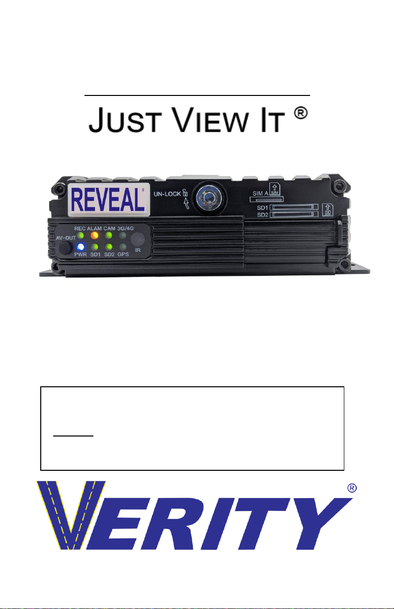
Verity Audio Reveal REC02U User manual

1
REVEAL
Operating Instructions for REC02U
HD 4-CH Dual SD Card Hybrid HD MDVR
Product Note:
SET THE TIME ZONE
Properly install (2) Class 10 256GB SD cards (Not included)
(1) 128GB Class 10 SD Card currently factory installed
Become familiar with retrieving video
Please read this manual completely before operating the SYSTEM
2023 Verity Rear Vision Systems / All rights reserved / Subject to Change
®

2
Contents
ABOUT US.................................................................................3
THINK SAFETY FIRST...............................................................4
SYSTEM FEATURES.................................................................6
SYSTEM OVERVIEW.................................................................8
SYSTEM OVERVIEW.................................................................9
REMOTE OVERVIEW...............................................................10
USER LOGIN ...........................................................................13
PASSWORD SETUP................................................................14
MODIFY / ADD USER...............................................................15
DELETE USER.........................................................................16
DATE AND TIME......................................................................17
VEHICLE SETUP .....................................................................19
INSTALL SD CARD..................................................................20
FORMAT SD CARD .................................................................20
RECORD SETUP .....................................................................22
RECORDING SCHEDULE........................................................23
MAIN STREAM (RECORDING) SETUP....................................24
SEARCH ..................................................................................25
WARRANTY.............................................................................27
Technical Support.....................................................................28

3
ABOUT US
Verity does not just buy systems off the shelf overseas, put
our logo on them, and ship them out. We work with
engineers, some at our location in Mishawaka, Indiana to
design camera systems to meet the safety needs of several
industries.
Where some companies just fall for the latest trend and
bring untested safety equipment to the market, we perform
the needed testing and often help factories make a better
product for which we employ the ODM (original design
manufacturing) method. We employ global engineers which
help us offer the latest technologies.
One step of every project we do is: “How will we defend it in
court?”By doing extensive testing, we know our product is
the best. We make our products Verity Safe™.
Optional
IR Extender
Control
Panel

4
THINK
SAFETY
FIRST
Read our manual before operating
or installing the REC02U.
Verity products are intended to be installed as a
supplement, and our observation systems and/or
products are not intended to be a substitute for mirrors
or other standard motor vehicle equipment which may
be required by law. Verity products promote improving
vehicle/driver operations. Our products are no
substitute for proper driving techniques, observance of
traffic laws, and motor vehicle safety regulations.
Installation Location
It is unlawful in most locals for any person to drive a
motor vehicle equipped with a television viewer/screen
located at any point forward of the back of the driver’s
seat (or in any location that is visible, directly or
indirectly to the driver) while operating the vehicle. Our
systems are designed to be used primarily as a rear
observation device.
DO NOT OPEN ANY COMPONENT. There are no
serviceable parts inside any Verity product. Opening
the product will break the tamper indicators and void
the warranty. If a problem should arise, please contact
our technical support 574-807-6004. For faster
response, fill out a service ticket found on our website.
www.veritysafe.com

5
WARNING
Do not pull cables tightly and add tension to
them. A drip loop is required where applicable.
Do not place cables where they can be
crushed in any manner.
CAUTION
To avoid damage to the electronic circuit, stop
using this product while doing welding work to
the vehicle and/or trailers.
When cleaning monitors and cameras, use a
damp lint-free cloth only.
Connect this unit only to other compatible
Verity components.
Although our products have built-in surge and
cross polarity protection, make sure all cables
are connected properly. Improper cable
connections may damage the camera and the
monitor.
Cables should not be allowed to touch hot or
rotating parts, such as the engine or exhaust.
Do not locate the monitor near heat-generating
vents or devices.
Turn off power to the monitor when connecting
the camera.
Monitors are not designed to be waterproof. (Our
SM07F waterproof monitor is the exception).
Exposure to water, such as rain, may damage the
unit.

6
SYSTEM FEATURES
Features:
H.265/H.264 image compression encoding
4 channels of D1/960H/AHD 720P simultaneous audio and
video recording/replaying
4- channel of 960H + 1- channel IPC 1080P HD camera full-
framed recording
Air video interface is used to provide high reliability and
strong anti-seismic property
Records 8 seconds after power failure
Two SD cards supported 256 GB for each. 2 x 256GB =
512GB storage
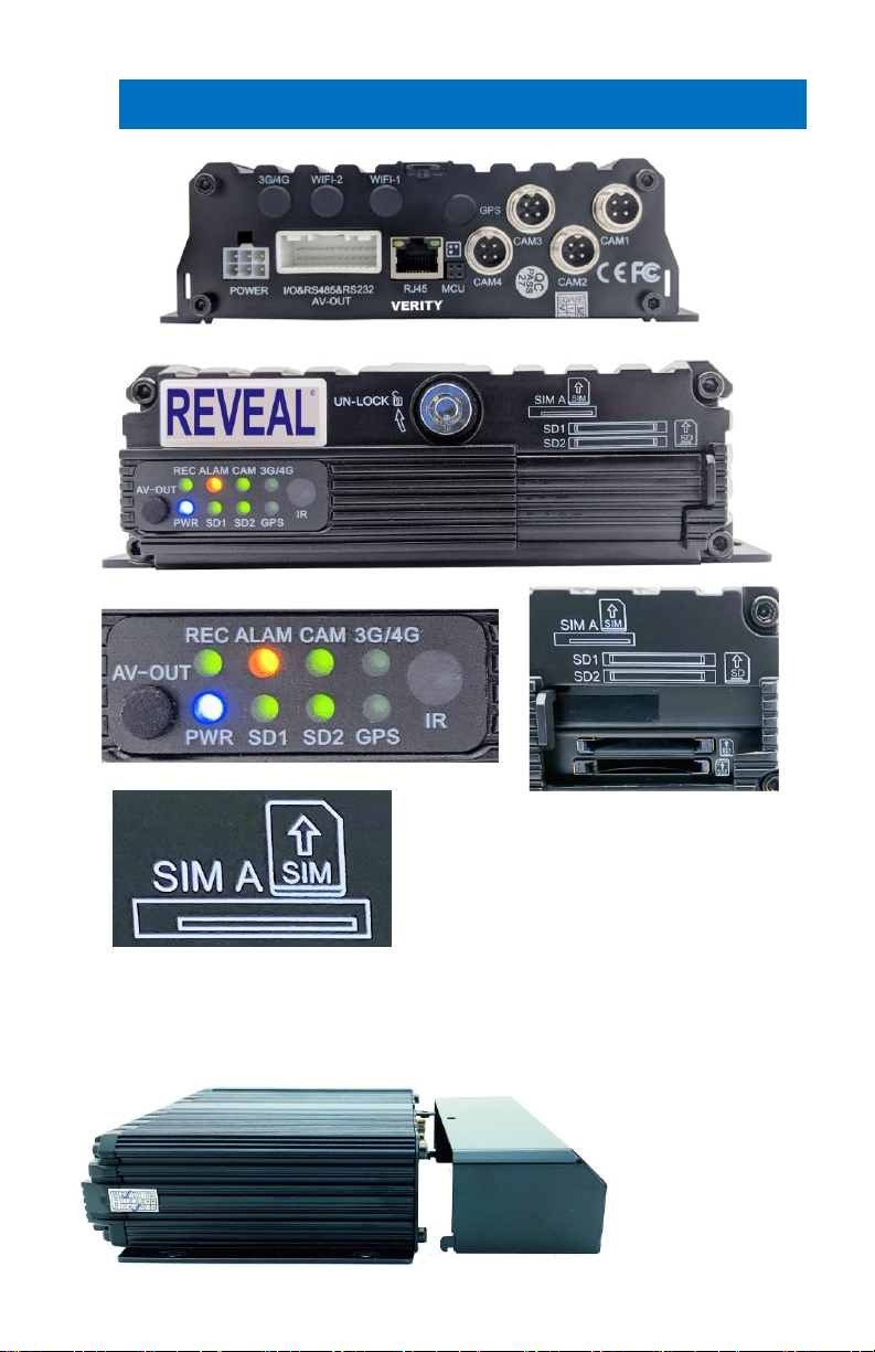
Unique inputs: 1 RS485 interface, 2 RS232 interfaces
8V-36V wide voltage DC supply
High/low-temperature resistance, operating under -25℃/
+75℃
System
Language: English / Chinese
Operation Interface: Graphical User Interface (OSD menu)
Two-Level Password Security: Administrator & User
Video
Video-Input: Supports 4 channels CIF/HD1/D1/960H/720P
camera video input
Supports 2-CH 720P AHD + 2-CH 960H analog mixing
Video input
Supports 1-CH 720P/1080P IPC + 4-CH 960H/D1/CIF Video
input
Note: 4 channels 720P AHD or 1-CH 720P/1080P IPC + 4-
CH 960H Video input will require high speed SD card ( >
80Mb/S, Class 10 or higher)
Video Output 2 Channels: front panel 3.5mm Jack, 4-pin rear
panel on 24 pin I/O Port.
Video Display: Single picture, 1~5 pictures
Signal System: PAL / NTSC - PAL@100 frame 720P/sec;
NTSC@120 frame 720P/sec

7
Audio
Audio Input: 4 Channels
Audio Output: 2 Channels - Front Panel 3.5mm Jack, Rear
Panel on 24pin I/O Port
Recording & Storage
Image Resolution: CIF / HD1 / D1 / 960H / 720P
Video Coding: ISO14496-10 Industry Standard
Video Bit Rate: CIF (Common Intermediate Format):
1536Kbps ~ 128Kbps
HD1/D1: 2048Kbps ~ 400Kbps
960H: 2048Kbps ~ 400Kbps
720P: 4096Kbps ~ 400Kbps
Select from 8 Levels of video image quality ranging from
1(Highest) to 8 (Lowest)
Audio Bit Rate: 40Kbps
Storage: 2 SD Card Slots, Up to 256GB each, Class 10 or
higher SD card required
Alarm
Alarm Input: 8 Channels, select trigger for either less than
1VDC or greater than 5VDC
Alarm Output: 1 Channel, 12V output
Communication Ports
RS485: 1 Port for PTZ controller or data device usage
RS232: 2 Ports for communication or data usage
RJ45 Network: 1 Port of RJ45, for connection to an IP
camera with a maximum of 1080P
Software
PC Playback A/V, files available for playback on PC. Limited
playback is also available on MDVR
Software Upgrade: via SD card
Power
Voltage Input: +8V~+36V 8~36, DC
Voltage Output: 12V (+/-0.2V) , Max 3A
Video Output Voltage: 2VP-P CVBS output analog signal
Dimensions
170 x 142 x 50mm including security cover 170x187x50mm

8
SYSTEM OVERVIEW
SIM A slot does not
apply to the REC02U
Metal Connector Tamper-resistant Cover
Security cover helps prevent tampering or damage to the
cable connection on the back of the MDVR.

9
SYSTEM OVERVIEW
DVR
REMOTE
CABLE
CONNECTION COVER
FRONT A V CABLE
AV OUT / SENSORS
POWER CABLES
KEYS & ACCESSORIES
MANUAL

10
REMOTE OVERVIEW
LOGIN: When the recorder is set with a password, press
the Login key to input your Password.
PTZ
KEY POINT: Because of security reasons, the DVR does
not provide password recovery and reset features.
Always keep a copy of your password written down.

11
INFO: Check information
Quad 4 Image Format:Number keys 1, 2, 3, 4 on the
monitoring interface, are used to switch between quad view
and single view; press the Quad View key to display 4
screens. You can press number 1/2/3/4 to display channel
1, channel 2, channel 3 and channel 4, respectively.
RETURN: Return to the previous menu, and finally exit from
the setup menu to the monitoring interface.
PAUSE/STEP: Used to pause playing or play images at a
single step. Press the key again to recover normal play
speed.
FRAME: Press this key to play a video in a frame rate.
PLAY: Press this key to start playing (search the video file
to be played and select, then press the key to play it.)
FWD Forward key in four grades: 2X,4X,8X,16X
REW Rewind key in four grades: 2X,4X,8X,16X
NEXT: Page down or roll to the next file
PREV: Page up or roll to the previous file
PTZ: Auto, preset, call, zoom +, zoom -, focus +, focus -,
aperture +, aperture -, PTZ, PRESET, RECALL,
BRUSH: F1, F2, F3, F1 is a key to start functional test
Important: Make sure the remote is facing the front of the
DVR during remote operations.
If you install the DVR behind a wall or in a cabinet, the IR
remote will not work.

12
For these applications, our IR extender will allow you to
place the DVR hidden behind a wall and use our ADD02CP.
This IR/LED panel has a 16 foot extended cable. This panel
provides feedback on the operation of the DVR. Never miss
another recording due to issues that may occur over the
years.
PWR: Power on light.
REC: Record light recording.
HDD:For hard drive units flashes when recording.
ALM: Indicates an “Alarm”event.
V-LOSS: Video loss light: flashes when video loss.
ERR: Error light
IR: IR receiver
The instructions for the ADD02CP will ship with the item.
2.2”
1.3”

13
USER LOGIN
Click the login button on the remote; the login interface will
appear. Please input your User Name, Password, and the
menu will show up.
The default UserName is admin, with a default password of
888888.
If you have not set these values, you can use the right arrow
button to pass through these.
To change the Password
To change the Password, In the Master menu, Click BASIC

14
PASSWORD SETUP
Then Click USER in the Basic Setup Screen
Password Set Up
# 1 Password on/off
# 2 ADD a user
# 3 MODIFY a user
# 4 DELETE a user
# 5 SAVE a user
IMPORTANT NOTE for security reasons, there is NO retrieval
option for passwords.
WRITE THE NEW PASSWORD DOWN!

15
MODIFY / ADD USER
When you add/modify a user, write down the password and
keep in a safe place (it cannot be retrieved). Enter NAME,
set LEVEL, add PASSWORD, and CONFIRM it. Click
SAVE.
There are two levels of users:
System user: Grants unlimited access and change

16
privileges, including creating User Accounts, Passwords,
and restricted access Rights
General user: Provides Password, limited rights
Password: 6 digits (numbers only)
*Confirm the new settings are correct and save the file.
Note: When working with users in the opening screen, you
need to select a user if you wish to modify or delete that
user.
DELETE USER
NOTE: Once a USER is deleted, it CANNOT be
undeleted.

17
DATE AND TIME
Click on
BASIC
Click on
TIME
DATE TIME: THIS IS IMPORTANT for timestamping
when recording. This is also necessary to allow for file
searching by date and time.
Date Format: Selectable
DST Switch: used to sets the parameters for the daylight
saving time option.
Time Format: 24 clock/military time or 12 hr. am/pm
Set Time Zone and Maintenance

18
1. It is advised to enable the auto-maintenance feature
when the device is operating for a prolonged time, allowing
the device automatically restarts within the set maintenance
time. NOTE: The DVR will reboot during this time. It will
stop recording during the quick reboot.

19
VEHICLE SETUP
To access, use the following:
Click on
BASICS
Click on
VEHICLE
Enter information related to the driver and company. The
DEVICE NUMBER is the only field required to have data
entered.
SERIAL NUMBER: predetermined, no input needed
BRANCH NAME: Company name (up to 20 characters)
OFFICER NAME: Driver name or ID (Up to 20 characters)
SIM NUMBER: phone number for a MDVR contained SIM
Card if installed

20
INSTALL SD CARD
Install SD Card 1: label side facing up
Install SD Card 2: Label side facing down
FORMAT SD CARD
To access, use the following:
Other manuals for Reveal REC02U
1
Table of contents
Other Verity Audio DVR manuals