Vermason 222610 Instruction Manual

Tester, Combination, 3-State
Operation, Installation and Maintenance
Pass Range 750K - 35M
UNIT C, 4TH DIMENSION, FOURTH AVENUE, LETCHWORTH, HERTS, SG6 2TD UK
Phone: 0044 (0) 1462 672005, Fax: 0044 (0) 1462 670440 • e-mail: [email protected], Internet: Vermason.co.uk
TB-7533 October 2009 Page 1 of 4 © 2009 Vermason
Figure 1. Vermason 222610 Combo Tester
Description
The Vermason Combo Tester is a 3-state
touch tester designed for fast and frequent
testing of ESD personnel grounding devices.
The Combo Tester incorporates a unique
dual test circuit design which improves
accuracy of testing and eliminates the need
for separate wrist strap and foot grounder
test units. The 222610 is equipped with a
750 Kilohm - 35 Megohm circuit, ideal for the
testing of wrist straps and footwear.
Test parameters are factory set but can be
adjusted to match your own specifications.
The Combo Tester is very simple to operate.
A green light signals the user that everything
is OK. A red light and an audible indicator
means that the circuit resistance is either too
low or too high.
The testers each include a
convertor, which converts the
banana plug on the face of
the unit into a 10mm snap.
NOTE: Once the convertor
has been put into the plug socket it cannot
be removed.
“The primary means of grounding personnel
shall normally be by a wrist strap connected
to an EBP [Earth Bonding Point].” (EN
61340-5-1 paragraph 5.5) “Wrist straps shall
be checked before use. Each check shall
be made with the wrist band worn in contact
with the wearer’s skin and with the ground
cord attached to the appropriate tester.” (EN
61340 5-1 paragraph 9.6) “The wrist strap
shall consist of a band that fits snugly around
the wrist and a cord to connect the band
to an EBP...The total resistance from hand
to EBP shall be in accordance with table
1 [Rg 7,5 x 10^5 to 3,5 x 10^7 ohms]. (EN
61340-5-1 paragraph 5.2.7)
“All wearers shall check that their heel and
toe straps meet requirements. The check
shall be made before entering the EPA.”
(EN 61340 5-1 paragraph 9.6.3) “When
the footwear/floor systems are used as the
primary means of grounding personnel,
the resistance of the combination shall be
determined by the ESD co-ordinator, and
is recommended to be between 7,5 x 10^5
ohms and 3,5 x 10^7 ohms.” (EN 61340-5-1
Table 1 Note 2)
The tester operates on either a 9 volt battery
or a special AC adapter. The combo tester
is available in two models: the tester alone,
or the tester with a stand. A footplate is also
available for use with the 222610.
CAUTION: Use only the AC adapter
designed for this unit. Using any other
adapters may damage the unit and void the
warranty.
Inspection
Remove the tester from the carton and
inspect for damage.
Items included with model 222610:
1 Combo Tester
1 9 volt battery
1 converter
1 Certificate of NIST calibration
Items included only with model 222611:
1 Combo Tester
1 Base Plate
1 Pedestal tube with bracket and boot
installed
1 10cm banana plug connector
1 Vinyl insulator cap
1 Wall poster
1 5/32” hex wrench
1 9 volt battery
1 converter
Model number 222611 is ideally suited for
testing foot grounding devices. Item number
222612 can also be used in conjunction with
the combo tester for testing of footwear.
Installation of Model 222610
The Combo Tester may be used as a
portable unit, or may be permanently
mounted on either a table or a wall. Please
refer to the following instructions when
installing your tester.
Stationary Installation
If you will be using the tester as a portable
unit you may prefer to mount the unit to a
table or wall. Three keyhole slots on the back
of the unit are included to allow you to attach
the tester to a stationary surface.
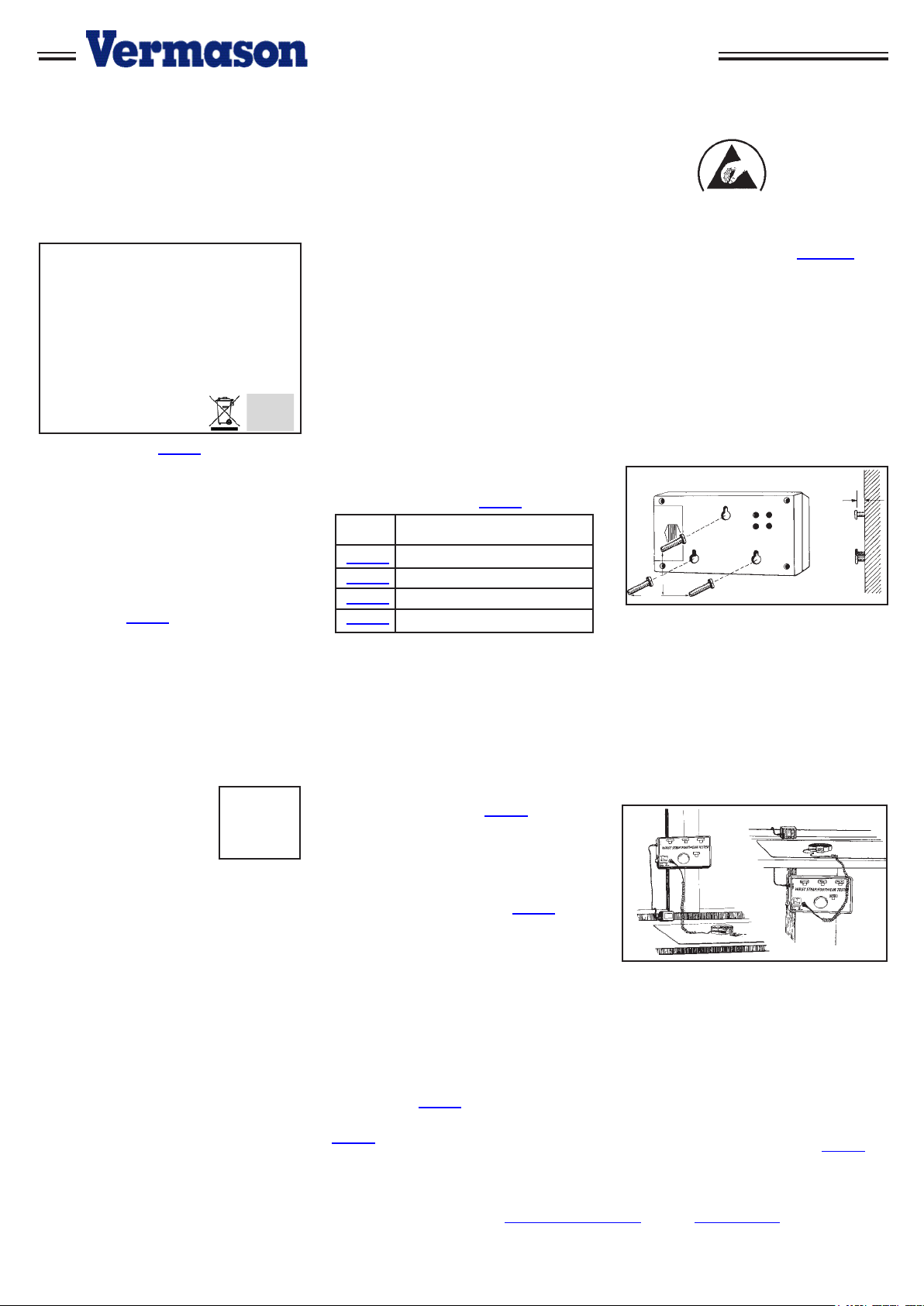
Figure 2. Mounting hole locations
1. Select location for mounting tester. Install
three #6 or #8 screws spaced as illustrated
in figure 3, into a wall or other vertical
surface. Make sure that the screw heads
do not project out more than 6.35 mm from
mounting surface. The template on page four
is actual size.
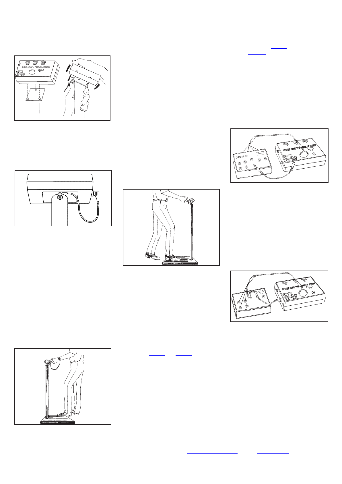
2. Mount the tester on the screws, pulling
down to lock it in place.
Figure 3. Stationary installation of the Combo
Tester
Operation
The Combo Tester can be operated either
on battery or AC power. The unit comes
equipped with a 9 volt alkaline battery. For
AC operation, plug the optional AC adapter
into the mini phone jack located on the upper
left hand corner of the tester. An AC adapter
is sold separately as item number 222625
(220 volt).
Model Description
222610 Tester, Banana Jack
222611 Tester w/stand
222612 Footplate, stainless steel
222625 AC Adapter, 220V
60mm
41mm
6mm
TECHNICAL BULLETIN TB-7533
Made in the
United States of America

LOW BATTERY INDICATOR
The Combo Tester includes a low battery
indicator alarm circuit. If both the audible
alarm and indicator LED turn on during use,
discontinue testing and replace the battery.
The tester will continue to operate with a
weak battery, but results should not be
considered accurate.
The battery can be easily replaced by
removing the battery compartment cover on
the back of the unit and installing a new 9
volt battery.
Figure 4. Replacing the battery
General Instructions
In the following test configurations, the
222610 can be used to test wrist straps while
they are worn. Model 222611 will also allow
the user to test footwear.
WRIST STRAP TESTING WITH MODELS
222610
This test safely checks that a continuous
path between the operator, wrist strap and
ground cord exists.
A. While wearing the wrist strap, plug the
banana plug end of the cord into the jack on
the face of the unit.
B. Press rocker switch toward “WRIST
CORD”.
C. Press the test button so that the unit
activates. Hold down for 2-3 seconds. Note:
Often the initial intermittency will be failure
of the strain relief connection to resistor
as simulated by ESD S1.1 paragraph 5.7
Bending Life Test.
Note: DO NOT TOUCH ANY OTHER
METAL WHILE PERFORMING TEST.
Figure 5. Testing of wrist strap grounding
assemblies
D. Lighting of the green “PASS” LED
indicates that the wrist strap and ground cord
assemblies are functioning properly.
E. If either red “FAIL LO” or “FAIL HI” LEDs
light and the audible indicator sounds, the
wrist strap wearer should check the wrist
strap assembly immediately.
TESTING FOOT GROUNDING DEVICES
In order to test footwear you will need the
model 222610 with the 222612 footplate,
or the 222611. The following instructions
are intended for use while wearing foot
grounding devices. When testing conductive
shoes, or foot grounders worn on both feet,
test each foot separately to ensure proper
operation and complete protection.
A. Place the Foot Plate on the floor in front
of the Combo Tester.
B. Plug the plate’s ground cord into the jack
on the left hand side of the unit.
Figure 6. Installing ground cord to “footplate”
jack
NOTE: Steps A and B are not required with
the 222611.
C. Place the rocker switch toward
“FOOTPLATE”.
D. Place one foot on the plate. If the floor is
conductive, lift the foot you are not testing off
of the floor during this test. Make sure there
is no cord plugged into the “WRISTCORD”
jack.
E. Press the test button so that the unit
activates. Hold for 2-3 seconds.
F. Lighting of the green “PASS” LED
indicates that the foot ground assemblies are
functioning properly.
G. If either red “Fail LO” or red “Fail HI”
LEDs light and the audible indicator sounds,
the wearer should check the foot grounding
device immediately.
H. Repeat steps C through F with other foot.
Figure 7. Testing foot grounding devices with
222610/222612
Free Standing Test Fixture
Assembly and Operation
(Model 222611)
Figure 8. The Free Standing Test Fixture
The 222611’s rugged steel pedestal tube
is powder coated in a non-conductive white
finish that helps to prevent false readings if
contacted by skin or loose smocks.
Figure 9. Attaching pedestal to baseplate
Assembly
A. Remove 3 screws from baseplate.
B. Position pedestal on the baseplate
with the tester mounting bracket pointing
away from the operator. Attach pedestal to
baseplate using the three screws provided.
Tighten with hex wrench provided.
C. Open the battery compartment and attach
the snap connector to the included 9 volt
battery. Attach poster to the wall at eye level
in front of the tester location.
UNIT C, 4TH DIMENSION, FOURTH AVENUE, LETCHWORTH, HERTS, SG6 2TD UK
Phone: 0044 (0) 1462 672005, Fax: 0044 (0) 1462 670440 • e-mail: [email protected], Internet: Vermason.co.uk
TB-7533 Page 2 of 4 © 2009 Vermason

D. Install the tester on the bracket by
aligning keyholes on the back of tester with
mounting studs on bracket. While pushing up
on thumb screw, insert the mounting studs
into the keyholes and slide the tester down.
See figure 10.
Figure 10. Installing tester on bracket
E. Install the 10cm banana plug connector to
“FOOTPLATE” jack on the side of the unit.
Insert ring terminal behind thumb screw.
F. Twist the thumb screw clockwise to
secure the tester to the bracket.
Figure 11. Secure tester to bracket
WRIST STRAP TESTING
This test verifies that a continuous path
between the operator, wrist strap, and
ground cord exists.
A. While wearing the wrist strap, plug the
banana plug end of the cord into the jack on
the face of the unit marked “WRIST CORD”.
B. Press rocker switch toward
“WRIST CORD”.
C. Press the test button so that the unit
activates. Hold down for 2-3 seconds while
flexing coil cord area near resistor.
NOTE: DO NOT TOUCH ANY OTHER
METAL WHILE PERFORMING TEST.
Figure 12. Testing of wrist strap grounding
assemblies
D. Lighting of the green “PASS” LED
indicates that the wrist strap and ground cord
assemblies are functioning properly.
E. If either red “FAIL LO” or “FAIL HI” LEDs
light and the audible indicator sounds, the
wrist strap wearer should check the wrist
strap assembly immediately.
TESTING FOOT GROUNDING DEVICES
When testing conductive shoes or heel
straps, test each foot separately to ensure
proper operation and complete protection.
A. Press rocker switch toward
“FOOTPLATE”.
B. Place one foot on the baseplate. If the
floor is conductive, lift the foot you are not
testing off of the floor during this test. Make
sure there is no ground cord plugged into the
“WRIST CORD” jack.
C. Press the test button so that the unit
activates. Hold down for 2-3 seconds while
flexing coil cord area near resistor.
NOTE: DO NOT TOUCH ANY
OTHER METAL WHILE PERFORMING
TEST.
Figure 13. Testing foot grounding devices
D. Lighting of the green “PASS” LED
indicates that the foot ground assemblies are
functioning properly.
E. If either red “FAIL LO” or “FAIL HI” LEDs
light and the audible indicator sounds, the
wearer should check the foot grounding
device immediately.
F. Repeat steps A through C with other foot.
Calibration
The models 222610 and 222611 are
calibrated to factory standards. We
recommend that calibration is performed
annually to ensure that the Tester is
operating within limits. Due to its dual circuit
design both test circuits of the Combo Tester
must be calibrated individually.
THUMB SCREW
Vermason offers a calibration unit that
is specifically designed to simplify the
calibration procedure. This unit comes
calibrated to factory standards. For additional
information on the 222650, ask for Technical
Bulletin TB-7542.
750 Kilohm - 35 Megohm TEST RANGE -
WRIST STRAPS
The following resistance should give the
display shown:
Resistance Value Test Output
(±5% or better)
675 Kilohm Red (Fail Lo)
825 Kilohm Green (Pass)
35 Megohm Green (Pass)
40 Megohm Red (Fail Hi)
Figure 14. Calibration of the Combo Tester
750K to 35 M range with the model 222650
750 Kilohm - 35 Megohm TEST RANGE -
FOOTWEAR
The following resistance should give the
display shown:
Resistance Value Test Output
(±5% or better)
675 Kilohm Red (Fail Lo)
825 Kilohm Green (Pass)
35 Megohm Green (Pass)
40 Megohm Red (Fail Hi)
Figure 15. Calibration of the Combo Tester
750K to 35M range with the model 222650
To calibrate, simply test each resistance
value shown above which are included in
the 222650 Calibration Unit. Test across
the test button and “WRIST CORD” jack for
calibration of the 750 Kilohm - 35 Megohm
range. Test across the test button and
“FOOTPLATE” jack for calibration of the
750K - 35M range. Be sure rocker switch is
set correctly.
UNIT C, 4TH DIMENSION, FOURTH AVENUE, LETCHWORTH, HERTS, SG6 2TD UK
Phone: 0044 (0) 1462 672005, Fax: 0044 (0) 1462 670440 • e-mail: [email protected], Internet: Vermason.co.uk
TB-7533 Page 3 of 4 © 2009 Vermason

Observe the LED’s for the proper response
as indicated. Be sure to hold the cord at
an insulated point, so that resistance value
is not affected by the body. Should testing
reveal that the Tester is not functioning
properly, verify that the battery or power
supply is operating correctly.
Tester calibration can also be verified
with the use of discrete resistors and two
banana-to-alligator cords.
Adjustment
Detailed adjustment instructions are available
from the factory. Unauthorized modifications
will void the product warranty. Servicing
should be performed only at the factory. See
warranty section for repair information.
Limited Warranty
Vermason expressly warrants that for a period
of one (1) year from the date of purchase,
Vermason Combination Testers will be free of
defects in material (parts) and workmanship
(labour). Within the warranty period, a unit will
be tested, repaired or replaced at Vermason’s
option, free of charge. Call Customer Service
at
0044 (0) 1462 672005
for a Return Material
Authorisation (RMA) and for proper shipping
instructions and address. Any unit under
warranty should be shipped prepaid to the
Vermason factory. You should include a copy
of your original packing slip, invoice, or other
proof of purchase date. Warranty repairs will
take approximately two weeks.
If your unit is out of warranty, Vermason
will quote repair charges necessary to bring
your unit to factory standards. Call Customer
Service at
0044 (0) 1462 672005
for a Return
Material Authorisation (RMA) and proper
shipping instructions and address.
Warranty Exclusions
THE FOREGOING EXPRESS WARRANTY IS
MADE IN LIEU OF ALL OTHER PRODUCT
WARRANTIES, EXPRESSED AND IMPLIED,
INCLUDING MERCHANTABILITY AND
FITNESS FOR A PARTICULAR PURPOSE
WHICH ARE SPECIFICALLY DISCLAIMED.
The express warranty will not apply to defects
or damage due to accidents, neglect, misuse,
alterations, operator error, or failure to properly
maintain, clean or repair products.
Limit of Liability
In no event will Vermason or any seller be
responsible or liable for any injury, loss or
damage, direct or consequential, arising
out of the use of or the inability to use the
product. Before using, users shall determine
the suitability of the product for their intended
use, and users assume all risk and liability
whatsoever in connection therewith.
DRILL PATTERN
FOR
COMBO TESTER
ACTUAL SIZE
Specifications
222610 and 222611
Wrist strap circuit
“Hi” Fail Factory set at 40M ohms
“Lo” Fail Factory set at 675K ohms
Footground circuit
“Hi” Fail Factory set at 40Mohms
“Lo” Fail Factory set at 675K ohms
General Characteristics
Power 9 volt battery or optional AC
power supply
Operation Resistance bridge
Readout Three LED’s & audible
alarm
Accuracy ±20%
Weight 227 grams
Height 14cm L x 4cm H x 8cm W
UNIT C, 4TH DIMENSION, FOURTH AVENUE, LETCHWORTH, HERTS, SG6 2TD UK
Phone: 0044 (0) 1462 672005, Fax: 0044 (0) 1462 670440 • e-mail: [email protected], Internet: Vermason.co.uk
TB-7533 Page 4 of 4 © 2009 Vermason
This manual suits for next models
3
Other Vermason Test Equipment manuals

Vermason
Vermason 223002 Installation and operating instructions

Vermason
Vermason TB-7545 Service manual

Vermason
Vermason 222693 User manual

Vermason
Vermason 222696 User manual

Vermason
Vermason 222635 Installation guide

Vermason
Vermason ZVM LIMMIT COMPARATOR User manual

Vermason
Vermason 225221 Owner's manual

Vermason
Vermason 222504 Owner's manual

Vermason
Vermason 223001 Installation and operating instructions

Vermason
Vermason 222523 Installation and operating instructions