manuals.online logo
Brands
  1. Home
  2. •
  3. Brands
  4. •
  5. Vermason
  6. •
  7. Test Equipment
  8. •
  9. Vermason 222523 Installation and operating instructions

Vermason 222523 Installation and operating instructions

HIGH SPEED, HIGH ACCURACY PERSONNEL
TESTER AND STAND
Installation, Operation and Maintenance
UNIT C, 4TH DIMENSION, FOURTH AVENUE, LETCHWORTH, HERTS, SG6 2TD UK
Phone: 0044 (0) 1462 672005, Fax: 0044 (0) 1462 670440 • e-mail: Service@Vermason.co.uk, Internet: Vermason.co.uk
TB-7536 December 2008 Page 1 of 2 © 2008 Vermason
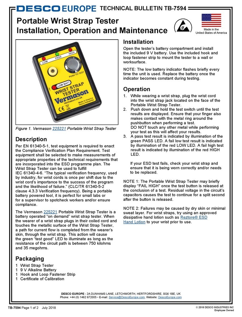
Figure 1. 222523 Personnel Test
Stand.
Description
A digital instrument with a
programmable IC at its heart that will
test the resistance of an operator's
grounding system(s) mounted on a
black metal frame with a black
wooden base board. The 222522 will
test the operator's ESD footwear.
The 222523 will additionally test the
operator's wrist strap. The stations
test both feet simultaneously. The
instrument will indicate whether the
resistance is in the ranges specified
in EN 61340-5 and ANSI/ESD S1.1 &
S20.20.
“Wrist straps shall be checked before
use. Each check shall be made with
the wrist band worn in contact with
the wearer's skin and with the ground
cord attached to the appropriate
tester.” (EN 61340 5 1 paragraph 9.6
Daily checks, paragraph 9.6.2 Wrist
strap) “Where toe and heel straps
are used as ESID footwear, once
these are worn outside the EPA [ESD
protected area], particularly on
carpets, they are likely to accumulate
fluff and become ineffective; this
requires that they be checked or
replaced on every visit to the EPA.
…When ESD footwear is used, it
should be noted that ESD footwear
alone cannot achieve protection, but
needs to be used in conjunction with
a suitable ESID floor.” (EN 61340-5-2
Paragraph 5.2.8 Footwear) “All
wearers shall check that their heel
and toe straps meet requirements [of
Table 1 NOTE 2 – ‘When the
footwear/floor systems are used as
the primary means of grounding
personnel, the resistance of the
combination shall be determined by
the ESD co-ordinator, and is
recommended to be between 7,5 x
10E5 ohms1 and 3,5 x 10E7 ohms’].
The check shall be made before
entering the EPA.” (EN 61340 5-1
Daily checks, paragraph 9.6.3 Non-
permanent footwear)
Inspection
Remove the test unit from the carton
and inspect for shipping damages.
Each 222522 unit should include the
following:
1 Test unit, item #222522
1 Test Stand Assembly
Each 222523 unit should include the
following:
1 Test unit, item #222523
1 Test Stand Assembly
Installation
1. Remove the components from the
packaging.
2. Lay out the baseboard and upright
bar using the packaging to protect
the paintwork.
3. Stand the baseboard on the rear
edge and offer the upright to
connect the 2 leads and align the
4 bolt holes.
4. With the leads connected, feed the
surplus cord back into the upright,
and then fit the four bolts from the
top. The washers and nuts can
then be fitted and tightened.
5. Stand the test stand up.
6. Insert the tester plugs through the
two larger holes in the instruction
panel. The connectors on the back
of the tester fit into the sockets on
the upright.
7. Place both in position, using the
two M5 bolts to secure the tester
& panel to the upright.
8. Perform a check on each plate
individually to check the
connections. If practical, remove a
shoe and stand in stockinged feet
on one footplate. Perform a test -
you should obtain a pass or fail
low. (Most likely fail low). Repeat
the test with the foot on the other
test plate.
9. The test station is now ready for
use.
Procedure to test footwear
1. Wear ESD shoes or heel
grounders as prescribed.
2. Stand on the footplates.
3. Press the round metal button on
the tester with one or two fingers.
The tester will now indicate
whether the total resistance is
within the acceptable range.
4. Green light and buzzer indicate
that the total resistance is either
less than 10MΩor less than
35MΩ.
Green = OK
You may now enter the EPA.
5. A red light indicates non-
conformance.
Red = FAIL
Do not proceed in the usual
manner but contact your
supervisor or follow your company
procedure.
6. Contact your supervisor if the
battery low light comes on.
Procedure to test wrist strap
1. Wear wristband. Choose one that
fits snugly or adjust it to do so.
2. Connect the ground cord securely
to the band using the snap
connector.
3. Connect the other end of the cord
to a matching termination on the
tester.
TECHNICAL BULLETIN TB-7536
Made in Britain
4. Push the round metal button in the
centre of the tester with one finger.
The tester will now indicate
whether the total resistance is
within the acceptable range.
5. Green light and buzzer indicate
that the total resistance is either
less than 10MΩor less than
35MΩ.
Green = OK
You may now enter the EPA.
6. A red light indicates
non-conformance.
Red = FAIL
Do not proceed in the usual
manner but contact your
supervisor or follow your company
procedure.
7. Contact your supervisor if the
battery low light comes on.
In case of non-conformance
The instrument measures the
resistance of the external circuit
between the metal contact button and
the cord connectors or the foot test
plates. The wristband and cord, the
plates and the footwear, the
connection to the operator, the
operator's body resistance and the
fingertip button contact are all part of
the circuit. In case of a failure being
indicated, determine whether the
wrist strap or the footwear alone is
failing by ensuring that the other
elements of the circuit are sound.
Note:
If 'battery low' light comes on, insert a
new 9volt alkaline PP3 battery. The
'battery low' threshold is factory set at
6.5 volt.
Calibration
All resistances are in-built using
matched fixed resistors. They are
measured using an ohmmeter, which
Limited Warranty
Vermason expressly warrants that for a period
of one (1) year from the date of purchase,
Vermason
High Speed, High Accuracy
Personnel Testers and Stands
will be free of
defects in material (parts) and workmanship
(labour). Within the warranty period, a unit will
be tested, repaired or replaced at Vermason’s
option, free of charge. Call Customer Service
at
0044 (0) 1462 672005
for a Return Material
Authorisation (RMA) and for proper shipping
instructions and address. Any unit under
warranty should be shipped prepaid to the
Vermason factory. You should include a copy
of your original packing slip, invoice, or other
proof of purchase date. Warranty repairs will
take approximately two weeks.
If your unit is out of warranty, Vermason will
quote repair charges necessary to bring your
unit to factory standards. Call Customer
Service at
0044 (0) 1462 672005
for a Return
Material Authorisation (RMA) and proper
shipping instructions and address.
Warranty Exclusions
THE FOREGOING EXPRESS WARRANTY IS
MADE IN LIEU OF ALL OTHER PRODUCT
WARRANTIES, EXPRESSED AND IMPLIED,
INCLUDING MERCHANTABILITY AND
FITNESS FOR A PARTICULAR PURPOSE
WHICH ARE SPECIFICALLY DISCLAIMED.
The express warranty will not apply to defects
or damage due to accidents, neglect, misuse,
alterations, operator error, or failure to properly
maintain, clean or repair products.
Limit of liability
In no event will Vermason or any seller be
responsible or liable for any injury, loss or
damage, direct or consequential, arising out of
the use of or the inability to use the product.
Before using, users shall determine the
suitability of the product for their intended use,
and users assume all risk and liability
whatsoever in connection therewith.
is of known accuracy and standards
used are traceable to UKAS. No
variable resistors e.g. potentiometers
are used. The resistances should
nonetheless be re-checked once a
year.
Use a calibration unit such as our
product code 223002.
The potentiometers are accessible
through the two holes on the left-
hand side of the case. The upper
hole allows the upper limit to be
adjusted, the lower hole the lower
limit. Follow the procedure described
on TB-7543. Alternatively, we offer a
calibration service.
Specifications
Resistance Limits
Wrist straps: Low - 0.75MΩ
High - 10 and 35MΩ
Foot wear: Low - 0.1MΩ
High - 10 and 35MΩ
Accuracy ±5%
Weight
(of tester) 0.1kg excluding
battery
Weight
(of test station)approx. 8kg
Dimensions
(of tester) 145 x 90 x 32mm
Power supply 1 x 9 volt PP3 cell,
preferably alkaline
Battery life typical 2500 tests (5s
per test)
Test voltage maximum 24V
Short circuit
current 12µA max
UNIT C, 4TH DIMENSION, FOURTH AVENUE, LETCHWORTH, HERTS, SG6 2TD UK
Phone: 0044 (0) 1462 672005, Fax: 0044 (0) 1462 670440 • e-mail: Service@Vermason.co.uk, Internet: Vermason.co.uk
TB-7536 Page 2 of 2

Other Vermason Test Equipment manuals

Vermason 223002 Installation and operating instructions

Vermason

Vermason 223002 Installation and operating instructions

Vermason 222696 User manual

Vermason

Vermason 222696 User manual

Vermason TB-7545 Service manual

Vermason

Vermason TB-7545 Service manual

Vermason 222700 User manual

Vermason

Vermason 222700 User manual

Vermason 223001 Installation and operating instructions

Vermason

Vermason 223001 Installation and operating instructions

Vermason 225706 Installation and operating instructions

Vermason

Vermason 225706 Installation and operating instructions

Vermason 222504 Owner's manual

Vermason

Vermason 222504 Owner's manual

Vermason 222644 Installation guide

Vermason

Vermason 222644 Installation guide

Vermason 225221 Owner's manual

Vermason

Vermason 225221 Owner's manual

Vermason ZVM LIMMIT COMPARATOR User manual

Vermason

Vermason ZVM LIMMIT COMPARATOR User manual

Vermason 222635 Installation guide

Vermason

Vermason 222635 Installation guide

Vermason 222693 User manual

Vermason

Vermason 222693 User manual

Vermason 222610 Instruction Manual

Vermason

Vermason 222610 Instruction Manual

Popular Test Equipment manuals by other brands

Fluke 525A Service manual

Fluke

Fluke 525A Service manual

Fluke 6270A Service manual

Fluke

Fluke 6270A Service manual

LeCroy 4300B Operator's manual

LeCroy

LeCroy 4300B Operator's manual

ACS UK1401 Operation manual

ACS

ACS UK1401 Operation manual

Mastech MS6810 user manual

Mastech

Mastech MS6810 user manual

Megger MPU690 user guide

Megger

Megger MPU690 user guide

AEMC 3640 user manual

AEMC

AEMC 3640 user manual

Nace CP 1 Course manual

Nace

Nace CP 1 Course manual

EPA LEAKWATCH LW-MZ-50 instruction manual

EPA

EPA LEAKWATCH LW-MZ-50 instruction manual

Megger MIT200 Series user guide

Megger

Megger MIT200 Series user guide

Tektronix 5 Series Declassification and security instructions

Tektronix

Tektronix 5 Series Declassification and security instructions

EUTECH INSTRUMENTS WATERPROOF ORPTESTR 10 ORPREDOX instruction manual

EUTECH INSTRUMENTS

EUTECH INSTRUMENTS WATERPROOF ORPTESTR 10 ORPREDOX instruction manual

Autel MaxiTPMS TS601 manual

Autel

Autel MaxiTPMS TS601 manual

Megger MFT1741 user guide

Megger

Megger MFT1741 user guide

Kurth Electronic KE7100 operating manual

Kurth Electronic

Kurth Electronic KE7100 operating manual

JGR PT1 user manual

JGR

JGR PT1 user manual

LeCroy PP005A instruction manual

LeCroy

LeCroy PP005A instruction manual

ISA MC5 user guide

ISA

ISA MC5 user guide

manuals.online logo
manuals.online logoBrands
  • About & Mission
  • Contact us
  • Privacy Policy
  • Terms and Conditions

Copyright 2025 Manuals.Online. All Rights Reserved.