CALIBRATION UNIT FOR PERSONNEL TESTERS
Installation, Operation and Maintenance
UNIT C, 4TH DIMENSION, FOURTH AVENUE, LETCHWORTH, HERTS, SG6 2TD UK
Phone: 0044
(0) 1462
672005, Fax:
0044 (0)
1462 670440
• e-mail:
[email protected], Internet: Vermason.co.ukTB-7543 January 2011 Page 1 of 2 © 2011 Vermason
Figure 1. 223002 calibration unit.
Description
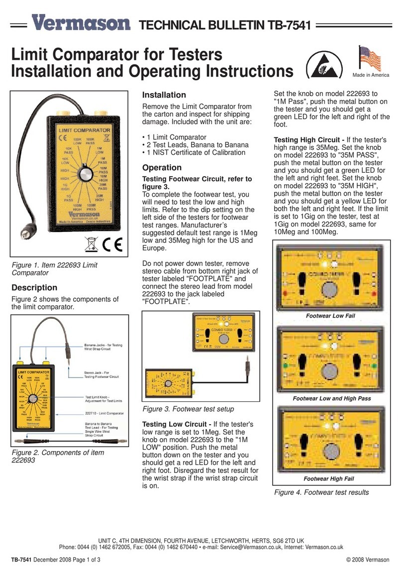
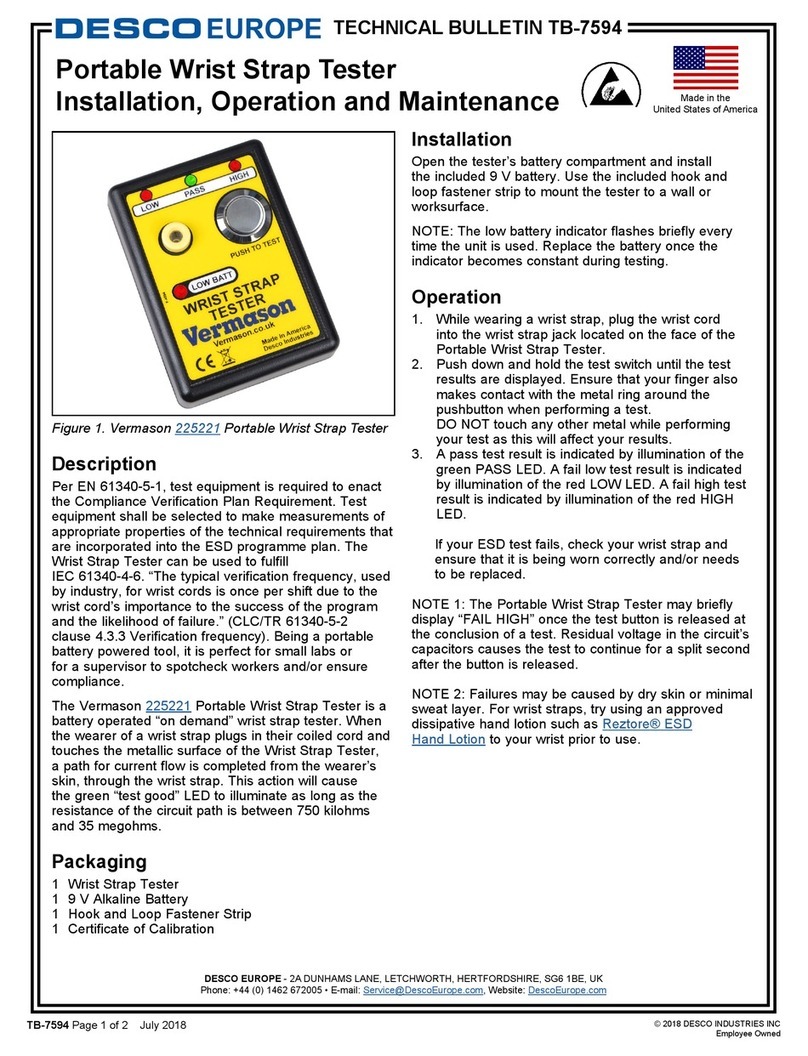
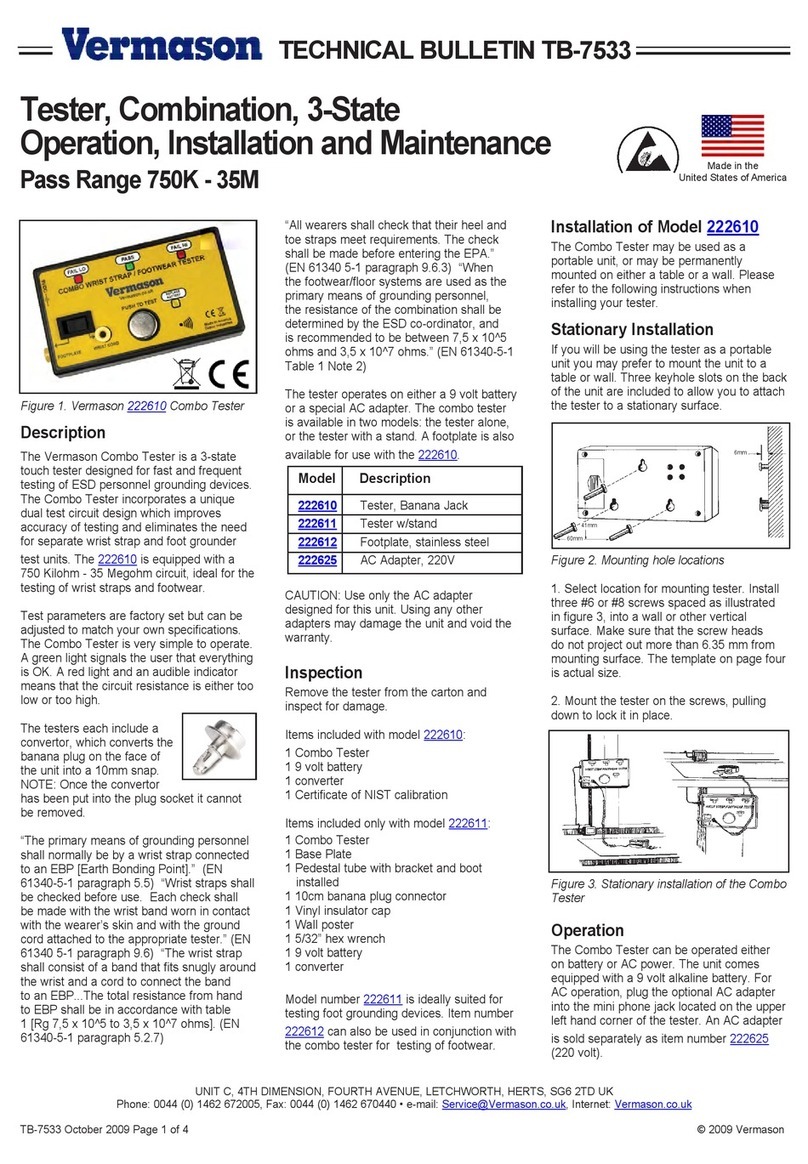
The Vermason calibration unit is
essentially a resistance box to be
used for calibrating either a wrist
strap tester or a footwear tester. The
calibration unit is set to cover limits
as specified in EN61340-5 and ANSI/
ESD S20.20. The unit is supplied
with a socket-to-socket adaptor and
a test certificate.
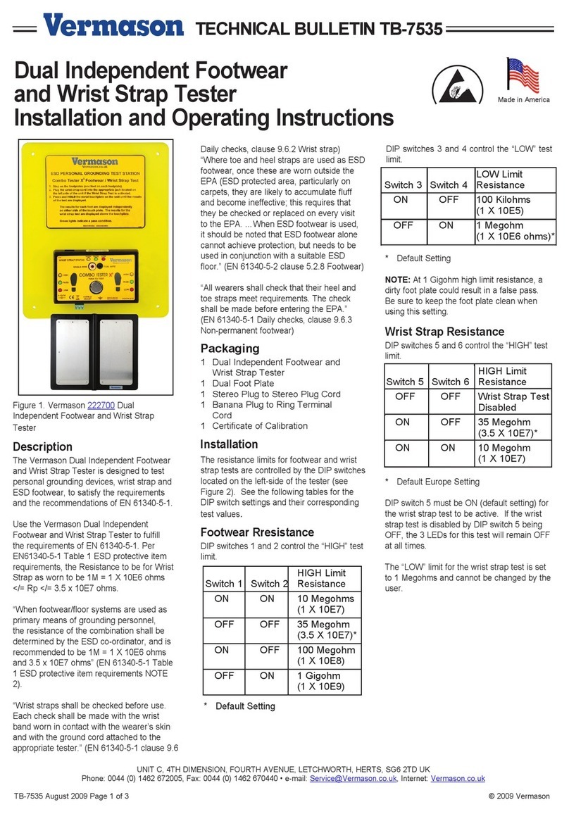
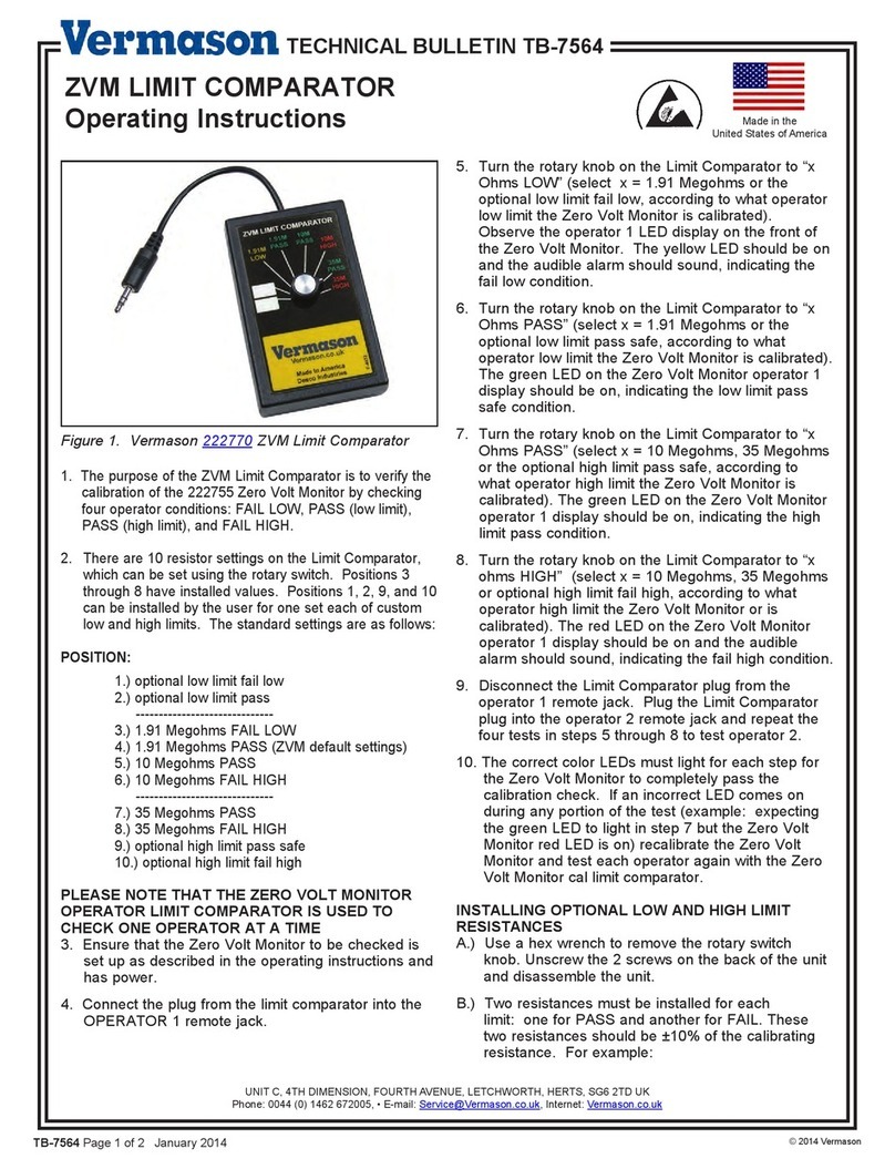
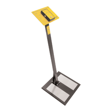
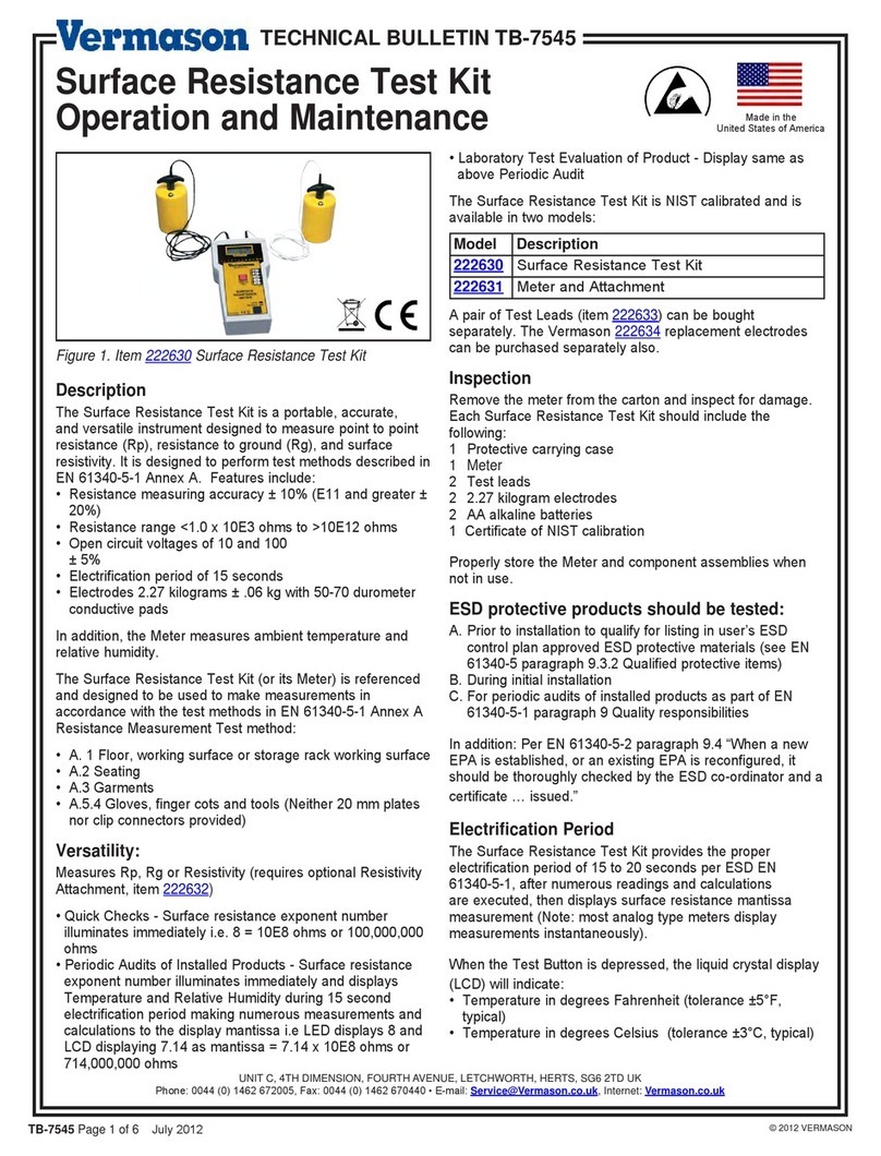
This device is intended to verify the
settings of Vermason testers 222508,
222514, 222518 and 222535. If a
faulty unit is found it is recommended
that you return the unit to Vermason
Ltd for recalibration. If you wish to
perform recalibration yourself, it is
possible using a method of trial and
improvement.
Inspection
Remove the calibration unit from
the carton and inspect for shipping
damages. Each unit includes the
following:
1 Calibration unit, item #223002
1 10mm socket to 10mm socket
adaptor
Calibration Test Procedures
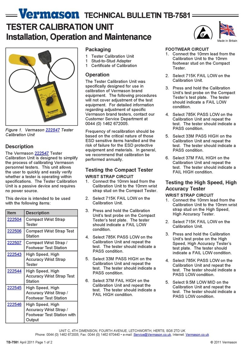
The calibration unit was specifically
designed for use in calibration of
Vermason brand test equipment.
The following step by step
procedures will cover calibration for
specific test units. The procedures
will not cover adjustment of the test
equipment. For detailed information
regarding adjustment of specific
Vermason brand testers contact our
Customer Service Department at 00
44 (0) 1462-672005.
How to test a wrist strap
tester
1. Connect the calibration unit lead
that is terminated with a 10mm
socket to the 10mm stud of the
tester.
2. Turn the knob to the ‘FAIL LOW’
setting on the upper part of the dial
marked ‘Wrist strap’.
3. Place the probe with the
conductive rubber base onto the
test button of the tester, making
sure that the probe is placed in the
middle of the test button for
optimal reading.
4. Push and hold the probe onto the
test button.
5. The tester should indicate ‘FAIL
LOW’
6. Repeat this procedure for the
other wrist strap knob settings, in
each case the indication on the
instrument should correspond to
the knob setting. (Note that the
“Low mid” and “High mid”
positions refer to the “<10
megohms” and “<35 megohms”
thresholds of the tester.)
7. If the response is different to the
one selected, the tester will need
to be re-calibrated.
8. If the response is as expected
release he test button and switch
the calibration unit to the next
limit.
How to test a footwear tester
1. When calibrating the footwear
tester use the adapter supplied to
connect the tester lead to the
calibration box.
2. Repeat the same procedure as
above for wristband, but use the
footwear side of the calibration
box.
Recalibrating a faulty tester
1. If a tester is found to be out of
calibration it is recommended that
you return it to Vermason Ltd for
recalibration. If you wish to adjust
calibration yourself you may follow
this procedure.
2. Adjustments are made via two trim
pots, which can be accessed via
holes on the left hand side of the
unit. The lower trim pot adjusts the
10 megohms and 35 megohms
limits. The upper trim pot adjusts
the 100 kegohms and 750
kegohms limits.
3. The trim pots adjust the footwear
and wrist strap circuits
simultaneously.
4. Adjust the trim pots in ¼ turn
increments. When you have made
a change repeat the test to see if
you have adjusted sufficiently.
5. If the LED to the left of the
expected LED is illuminating turn
the relevant trim pot clockwise. If
the LED to the right of the
expected LED is illuminating turn
the pot anti-clockwise.
6. When you have adjusted the trim
pot enough test the associated
position on the calibration unit to
ensure you have not adjusted too
far.
7. When complete perform a full set
of tests again.
TECHNICAL BULLETIN TB-7543
Made in Britain

