Circutor MPC-20 User manual

STEP AND TOUCH VOLTAGE TESTER
GROUND RESISTANCE
TESTER
MPC-20 (20 A) code 7 70 123
MPC-50 (50 A) code 7 70 075
INSTRUCTION MANUAL
( M98113601-20 / 03A )
(c) CIRCUTOR S.A.

--- MPC 20 & 50 TESTER - M-981136 (vers. BD) --- Page
2
1.- MPC-20 - MPC-50 .................................................................... 4
1.1 Usual operating procedure 4
1.2 Precautions whilst operating 5
2.- DESCRIPTION OF THE MAIN COMPONENTS ...................................... 6
2.1 Source of regulated voltage 6
2.2 Control and protection circuit 6
2.3 Voltage and current tester 6
2.4 Touch electrodes 6
2.5 Accessories 6
3.- CONTROL AND CONNECTION FEATURES OF THE MPC-20 / MPC-50 .... 7
3.1 Control Components 7
3.2 External connection components 7
3.3 Internal connection components 8
4.- MAIN FEATURES ............................................................................. 10
4.1.- Power supply 10
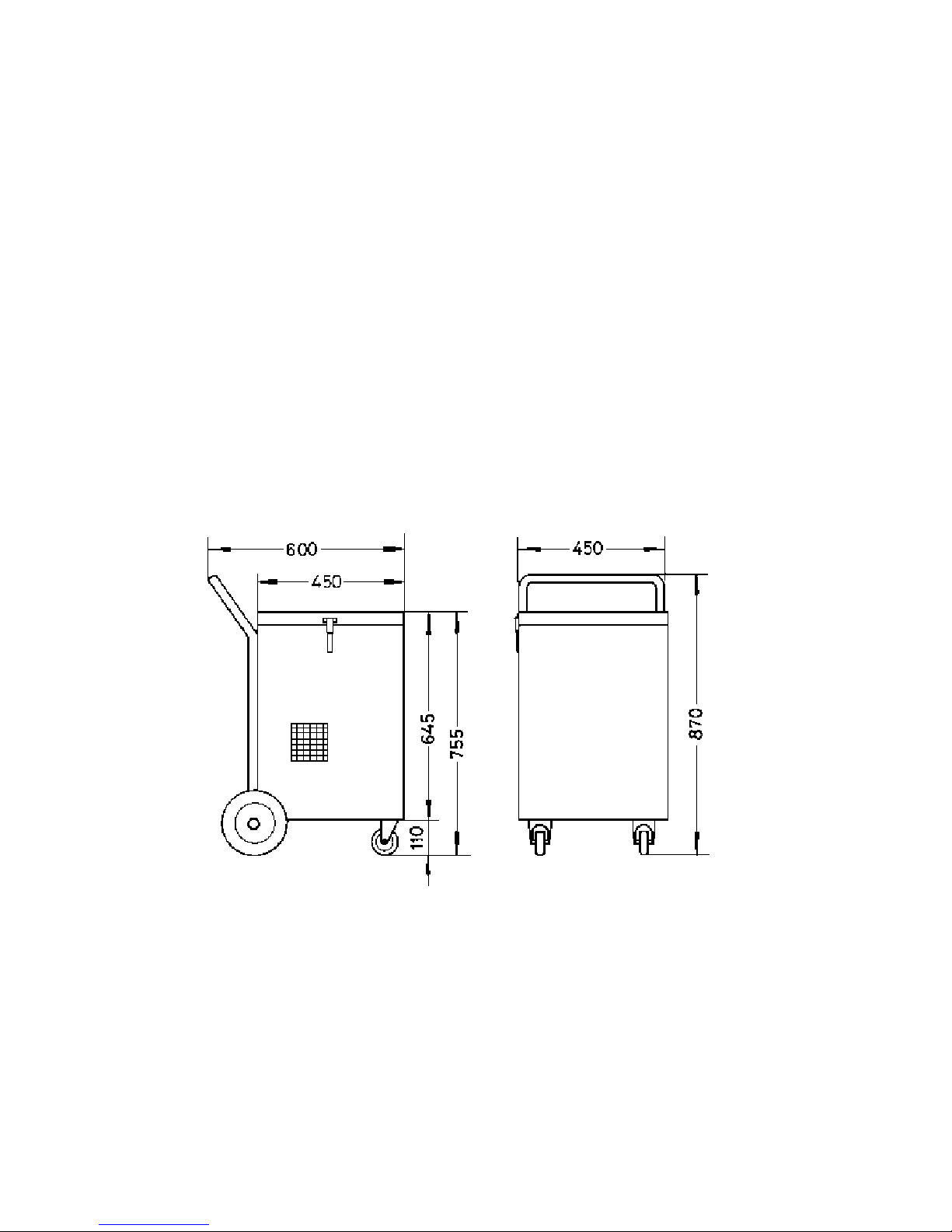
4.2.- Dimensions, weight:
5.1.1 Attaching the equipment 14
4.3.1 Features as a step and touch voltage tester. MPC-20 TESTER 11
4.3.2 Features as a step and touch voltage tester. MPC-50 TESTER 12
4.4.- Features as an ground resistance tester 13
5.- TESTING STEP OR CONTACT VOLTAGE............................................ 14
5.1 Installation and start-up 14
5.2 Attaching the MPC-20 / MPC-50 14
5.3 Auxiliary ground for current injection 14
5.4 Connecting the current circuit 16
5.5 Connecting the power supply 16
5.6 Setting the maximum default current 17
5.7 Attaching the testing electrodes 18
5.8 Button for testing erratic currents 18
5.9 Adjusting the current and testing the
STEP or TOUCH VOLTAGE 19
5.10 Test results 20
6.- TESTING GROUND RESISTANCE ..................................................... 21
6.1 Attaching and connecting the MPC-20 / MPC-50 22
6.2 Attaching the "MEASURING ROD" 22
6.3 Testing erratic voltages 22
6.4 Testing ground resistance 22
6.5 Test results 23
6.6 Repeating tests 24

--- MPC 20 & 50 TESTER - M-981136 (vers. BD) --- Page
3
CHAPTER II
7.- EXISTING STANDARDS ................................................................... 25
7.1 Abstract and table of voltages 25
7.2 Standards relating to the MPC-20 / MPC-50 26
8.- CORRECTION OF THE READ OUTS .......................................................... 27
9.- MAINTENANCE............................................................................... 29
10.- TECHNICAL SERVICE ..................................................................... 29

--- MPC 20 & 50 TESTER - M-981136 (vers. BD) --- Page
4
MPC-20 & MPC-50
1.- PRELIMINARY WARNINGS:
1.1.- USUAL OPERATING PROCEDURE
The MPC-20 and MPC-50 testers are compact and robust and are
designed to test where large powers are needed for a short period of time:
- MPC-20: up to 12 kVA
- MPC-50: up to 20 kVA
Its microprocessor controlled testing system ensures that tests are made
in approximately 10 seconds.
Its portability means that weight has been kept to a minimum with the
use of minimal loss toroidal transformers.
Heat generated by the transformer windings is continuously eliminated
by an in-built ventilation system. It is able to operate indefinitely, making 12 sec.
tests at 40 sec. intervals. If for any reason it overheats, a red indicator light will
show why and will prevent it from operating until normal temperature is re-
established.

--- MPC 20 & 50 TESTER - M-981136 (vers. BD) --- Page
5
1.2.- WARNINGS!
THE CURRENT USED FOR MEASUREMENTS, 20 A with the MPC-
20 and 50 A in the MPC-50, IS SUFFICIENT TO CREATE SIGNIFICANT
VOLTAGES AROUND THE ELECTRODES, ESPECIALLY THE AUXILIARY
ELECTRODES.
PLEASE TAKE ALL NECESSARY PRECAUTIONS TO AVOID
ACCIDENTS.
For example: A 5 Ohms auxiliary electrode creates a voltage of 250 V around
itself.
VOLTAGE MAY REACH 600 V AROUND THE CABLE OUTPUT with the
MPC-20 and 400 V with the MPC-50.
THE POWER CIRCUIT CONNECTIONS MUST NEVER BE
HANDLED WITHOUT HAVING FIRST STOPPED THE EQUIPMENT AND
REMOVED THE OPERATING KEY.
BEFORE ANY MEASUREMENTS ARE TAKEN, SIGNS MUST
PREVENT PEOPLE FROM PASSING THROUGH OR REMAINING IN THE
INJECTED CURRENT AREA. IN THE EVENT OF HIGH GROUND
RESISTANCES, VOLTAGES UP TO 600 V MAY BE CREATED, WHICH ARE
FATAL TO ANIMALS OR PERSONS NEAR TO THE DISPERSERS DURING
TESTS.

--- MPC 20 & 50 TESTER - M-981136 (vers. BD) --- Page
6
2.- DESCRIPTION OF THE MAIN COMPONENTS
2.1.- VOLTAGE SOURCE
MPC-20: voltage source, with 10 regulating scales using a switch and
fine adjustment using a dial. Supplies a regulable voltage between 0 and 600 V
and is set for a current of 20 A. It can test to 20 A in installations with a 30
Ohms resistance (ground and auxiliary added).
MPC-50: voltage source, with 8 regulating scales using a switch and fine
adjustment using a dial. Supplies a regulable voltage between 0 and 400 V and
is set for a current of 50 A. It can test to 50 A in installations with a 8 Ohms
resistance (ground and auxiliary added).
The remaining components are the same in each:
2.2.- CONTROL AND PROTECTION CIRCUIT
Button for testing erratic currents. Two directional selector key to control the
current injection (0º and 180º): Line voltage indicator. Over heating indicator.
Fuse protection for the operating circuit Protective circuit breakers for all the
equipment and for the output circuit.
2.3.- VOLTAGE AND CURRENT TESTER, controlled by micro-processor. It
test and also calculates Vp, Vc and Rt. The alphanumeric liquid crystal display
shows preset data, measurements and calculations.
2.4.- TOUCH ELECTRODES, that are cylindrical, 200 square cm at the base
and weigh 250 N, with carrying handles and terminals for connecting the testing
cables.
2.5.- ACCESSORIES. 50 metre cables, 10 mm in diameter with terminals for
current injection. 50 metre cables for voltage reading. Bridging cable to join the
two touch electrodes.

--- MPC 20 & 50 TESTER - M-981136 (vers. BD) --- Page
7
3.- CONTROL AND CONNECTION COMPONENTS OF THE MPC-20 & MPC-50
3.1.- CONTROL ELEMENTS
1 VOLTAGE OUTPUT SWITCH
MPC-20: FROM 1 TO 10
MPC-50: FROM 1 TO 8
Switch
Position
MPC-20 MPC-50
1 0 to 60 V 0 to 50 V
2 0 to 120 V 50 to 100 V
3 20 to 180 V 100 to 150 V
4 180 to 240 V 150 to 200 V
5 240 to 300 V 200 to 250 V
6 300 to 360 V 250 to 300 V
7 360 to 420 V 300 to 350 V
8 420 to 480 V 350 to 400 V
9 480 to 540 V
10 540 to 600 V
2 FINE REGULATION CONTROL (according to previous table)
3 RED TEMPERATURE INDICATOR
4 RED SYSTEM VOLTAGE INDICATING LIGHT
5 ANALOGUE AMMETER FOR ADJUSTMENT AND ASSISTANCE
6 GENERAL AND OUTPUT CIRCUIT BREAKER
7 SELECTOR WITH KEY OPERATE THE TEST
8 LIQUID QUARTZ DISPLAY
9 3 BUTTONS TO PRESET Imax VALUE
10 BUTTON TO SELECT OPERATING MODE (Vp/c or Rt)
11 BUTTON FOR ERRATIC VOLTAGE MEASUREMENTS
999
999999
999
ENTER
ENTERENTER
ENTER MODE
MODEMODE
MODE
3.2.- EXTERNAL CONNECTION COMPONENTS
12 OUTPUT TERMINALS: MAX 50 A, MAX 600 V
13 VOLTAGE INPUT TERMINALS TO THE VOLTMETER

--- MPC 20 & 50 TESTER - M-981136 (vers. BD) --- Page
8
3.3.- INTERNAL CONNECTION COMPONENTS
MPC-20:
30 AND 31 SINGLE PHASE POWER SUPPLY: 230 V
T.T TERMINAL WITH OBLIGATORY EARTHING CONNECTION
MPC-50:
30 AND 32 SINGLE PHASE POWER SUPPLY: 400 V
30 AND 31 SINGLE PHASE POWER SUPPLY: 230 V (EXCEPTIONAL)
T.T TERMINAL WITH OBLIGATORY EARTHING CONNECTION
SIZE:

--- MPC 20 & 50 TESTER - M-981136 (vers. BD) --- Page
9
Control panel:
999-> 999 ENTER ESC
RT-VPC
0º OFF 180º
(LLAVE)
ERRATICAS
ENTRADA TENSION
Vm
PILOTO RED
PILOTO TERMICO
CONMUTADOR DE
SALIDAS 1 AL 8
12
0
50
A
MPERIMETRO
INT. GENERAL
DISPLAY
VOLTAGE INPUT
CIRCUIT BREAKER LIGHT
SYSTEM LIGHT
GENERAL SWITCH
AMMETER
OUTPUT 1 TO 8
SWITCH
ERRATICS
(KEY)

--- MPC 20 & 50 TESTER - M-981136 (vers. BD) --- Page
10
4.- MAIN FEATURES
4.1.- POWER SUPPLY
POWER SUPPLY MPC-20 MPC-50
VOLTAGE
FREQUENCY
MAXIMUM CURRENT
CIRCUIT BREAKER
POWER SUPPLY CABLE
MAXIMUM POWER
230 ± 10 %
SINGLE PHASE
50 / 60 Hz
54 A
100 A
2 X 10 + 6 T.T.
12 kVA
400 ± 10 %
SINGLE PHASE
230 V exception
50 / 60 Hz
57 A to 400 V
(95 A to 230 V)
100 A
2 x 16 + 16 T.T.
20 kVA
4.2.- SIZES AND WEIGHT
SIZES:
HEIGHT 800 mm
WIDTH 550 mm
LENGTH 500 mm
WEIGHT: 142 Kg WITHOUT ELECTRODES
ELECTRODE SIZES:
HEIGHT 210 mm APPROX.
DIAMETER 160 mm APPROX.
WEIGHT: 25.5 Kg EACH

--- MPC 20 & 50 TESTER - M-981136 (vers. BD) --- Page
11
4.3.- TESTING STEP AND CONTACT VOLTAGE
4.3.1.- MPC-20 TESTER
CURRENT 0 ÷ 20 A REGULABLE
OVERVOLTAGE 1, 1 In, 1 Min
VOLTAGE 0 ÷ 600 V,
10 SCALES AND FINE ADJUSTMENT
MAX. RESISTANCE 30 OHMS (GROUND TESTED + AUXILIARY
GROUND)
RESISTANCE OF
HIGHER VALUES
ALLOWS TESTING AT LOWER CURRENTS
METHOD USED INJECTION AND TESTING OF CURRENT
(Ip)
TESTING VOLTAGE IN SURFACE AREA
(Vm)
DEFAULT SETTING Imax
CALCULATES: Vp/c=Vm xMax/Ip
ANALOGUE AMMETER
CLASS: 1.5
RANGE: 20 A
DIGITAL AMMETER CONTROLLED BY MICROPROCESSOR
ACCURACY: 0.5 % MEASUREMENTS ± 2
digits
MAX. : 99.9 A
RESOLUTION : 10 mA
MINIMUM READING : 20 mA
DIGITAL VOLTMETER CONTROLLED BY MICROPROCESSOR
SCALES : 30 V and 600 V
SCALE CHANGE : AUTOMATIC
ACCURACY: 0.5 % MEASUREMENTS ± 2
digits
MINIMUM READING : 20 mV
IMPEDANCE CUR. : 1000 ohms or 600
kohms (switch)
RESOLUTION : 10 mV
MAX. PROGRAMMABLE
CURRENT VALUE
9999 A
SELECTION OPERATING
MODE (Vp/c or Rt)
BY BUTTON (MODE) + Rt/Vp-c Selector
DEFAULT CURRENT
PRESELECTION
BY BUTTONS
TESTING ERRATIC
VOLTAGES
VOLTMETER CONTROL BY BUTTON
CONTROL OF STOP AND
START
BY SELECTOR WITH KEY:
ON 0°--- OFF --- ON 180º

--- MPC 20 & 50 TESTER - M-981136 (vers. BD) --- Page
12
4.3.2.- TESTING STEP AND CONTACT VOLTAGE: MPC-50 TESTER
CURRENT 0 ÷ 50 A REGULABLE
OVERVOLTAGE 1, 1 In, 1 Min
VOLTAGE 0 ÷ 400 V,
8 SCALES AND FINE ADJUSTMENT
MAX. RESISTANCE 8 OHMS (GROUND TESTED + AUXILIARY
GROUND)
RESISTANCE OF
HIGHER VALUES
ALLOWS TESTING AT LOWER CURRENTS
METHOD USED INJECTION AND TESTING OF CURRENT
(Ip)
TESTING VOLTAGE IN SURFACE AREA
(Vm)
DEFAULT SETTING Imax
CALCULATES: Vp/c=Vm x Max/Ip
ANALOGUE AMMETER CLASS : 1.5
RANGE : 50 A
OVERRANGE : 300 A
DIGITAL AMMETER CONTROLLED BY MICROPROCESSOR
ACCURACY: 0.5 % MEASUREMENTS ± 2
digits
MAX. : 99.9 A
RESOLUTION : 10 mA
MINIMUM READING : 20 mA
DIGITAL VOLTMETER CONTROLLED BY MICROPROCESSOR
SCALES : 30 V and 500 V
SCALE CHANGE : AUTOMATIC
ACCURACY: 0.5 % MEASUREMENTS ± 2
digits
MINIMUM READING : 20 mV
IMPEDANCE CUR. : 1000 ohms or 600
kohms (switch)
RESOLUTION : 10 mV
MAX PROGRAMMABLE
CURRENT VALUE
9999 A
SELECTION WORK
MODE (Vp/c or Rt)
BY BUTTON (MODE) + Rt/Vp-c Selector
DEFAULT CURRENT
PRESELECTION
BY BUTTONS
TESTING ERRATIC
VOLTAGES
VOLTMETER CONTROL BY BUTTON
CONTROL OF STOP AND
START
BY SELECTOR WITH KEY
ON 0°-- OFF --- ON 180º
4.4.- TESTING GROUND RESISTANCES
(USING CURRENTS UP TO 20 A or 50 A)

--- MPC 20 & 50 TESTER - M-981136 (vers. BD) --- Page
13
METHOD USED INJECTION AND TESTING OF CURRENT
MPC-20 : 0 ÷ 20 A
MPC-50 : 0 ÷ 50 A
TESTING VOLTAGE BETWEEN GROUND AND NEUTRAL AREA
(Vm)
CALCULATES: Rt.=Vm/Ip
ELECTRODES NEEDED GROUND TO MEASURE
DISTANT AUX ELECTRODE
"ROD" ELECTRODE FOR TAKING
VOLTAGE
MAXIMUM ERROR 3 % OF MEASUREMENTS ± 2 digits
DIGITAL AMMETER CONTROLLED BY MICROPROCESSOR
ACCURACY: 0.5 % MEASUREMENTS ± 2
digits
MAX. : 99.9 A
RESOLUTION : 10 mA
MINIMUM READING: 20 mA
DIGITAL VOLTMETER CONTROLLED BY MICROPROCESSOR
RANGES : 30 V and 500 V
RANGE CHANGE : AUTOMATIC
ACCURACY: 0.5 % MEASUREMENTS ±
2 digits
MINIMUM READING : 20 mV
IMPEDANCE CUR. : 600 kohms
RESOLUTION : 10 mV
SELECTION WORK
MODE (Vp/c or Rt)
BY BUTTON (MODE) + Rt/Vp-c Selector
TESTING ERRATIC
VOLTAGES
VOLTMETER CONTROL BY BUTTON
CONTROL OF STOP
AND START
BY SELECTOR WITH KEY
ON 0°-- OFF --- ON 180º

--- MPC 20 & 50 TESTER - M-981136 (vers. BD) --- Page
14
5.- TESTING STEP OR CONTACT VOLTAGE
5.3.- INSTALLATION AND START-UP
This manual contains information and warnings that must be followed by the
user to ensure the safe operation of the equipment and to maintain it in a safe
condition.
Usual operation must not be started until the final assembly of the cables
and weights, as recommended in section 1.2.- Connection instructions of this
manual.
If the equipment is used in a way not specified by the manufacturer, the
protection of the equipment and the people operating it may be
compromised.
When it is likely that there has been a loss of safety (e.g. when damage is
visible), the equipment must be disconnected from the power supply. In the
event please contact a qualified service representative.
5.4.- ATTACHING THE MPC-20/ MPC-5
To test correctly, the MPC-20 or the MPC-50 must be placed 20 or more
metres from the ground to be tested. Do not place it in the area occupied by the
electrodes in the ground.
5.5.- AUXILIARY GROUND FOR CURRENT INJECTION
There must be auxiliary ground for current injecting 50 or more metres away
from the ground to be tested Resistance between the auxiliary ground added to
the ground to be measured must not exceed 8 ohms for the MPC-50 and 30
Ohms for the MPC-20.
-----------------------------------------------------------------

--- MPC 20 & 50 TESTER - M-981136 (vers. BD) --- Page
15
DIAGRAM FOR TESTING STEP VOLTAGE
-----------------------------------------------------------------------------------------------------------
DIAGRAM FOR TESTING CONTACT VOLTAGE
GROUND
TO BE
TESTED
1 metre
Tested
volta
g
e
L (minimum 20
metres)
Test intensity lp
AUXILIARY
GROUND
L (minimum 20 metres)
GROUND
TO BE
TESTED
Metal parts
Tested
voltage
L (minimum 20
metres)
Test intensity lp
AUXILIARY
GROUND

--- MPC 20 & 50 TESTER - M-981136 (vers. BD) --- Page
16
5.6.- CONNECTING THE CURRENT CIRCUIT
ENSURE THAT THE SELECTOR (ON-OFF-ON) ON THE
MPC-20 & MPC-50 IS DISCONNECTED AND WITHOUT THE KEY.
Connect the "OUTPUT CABLES": to the ground to be measured and the
other to the auxiliary ground.
5.7.- CONNECTING THE POWER SUPPLY
5.7.1.- POWER SUPPLY FOR THE MPC-20:
Connect the supply cable to a 230 V II+TT system or an independent
generator with the same VOLTAGE.
5.7.2.- POWER SUPPLY FOR THE MPC-50:
Connect the supply cable to a 400 V II+TT system or an independent
generator with the same VOLTAGE (As an exception the MPC-50 may be
connected to 230 V).

--- MPC 20 & 50 TESTER - M-981136 (vers. BD) --- Page
17
5.8.- SETTING THE MAXIMUM DEFAULT CURRENT
Once the connections described above have been made and after taking
SAFETY MEASURES, testing can be done in the following way:
Place the regulator on the "0%" position.
Place the Voltage switch on position "1".
CONNECT THE MPC SWITCH. The model type and the version of the
setting will appear on the display.
Place the "OPERATING MODE" selector on "V p/c".
(Connect the 1000 Ohms resistance switch located on the back of the
equipment: voltmeter internal impedance of 1000 Ω).
PRESS the upper right "MODE" button (operating mode) and the display is
ready to start testing voltage ("V") or resistance ("Rt"). Use the said button to
select "V" on the display.
MAXIMUM CURRENT must be entered as preset in the installation
procedure. The value in A of the maximum current must be entered as a testing
constant. This value must be supplied by the electricity supply company
according to MIE-RAT-19.
Using the 3 buttons above the display, (, and Enter), SET THE
MAXIMUM DEFAULT CURRENT (maximum 9999):
a.- To enter setting, press () . The first lx digit will flash.
b.- To enter or change this value press () repeatedly: the digit flashing
at that time will increase.
c.- When the required value appears on the screen move on to the next
digit by pressing (), and so on changing the remaining values.
d.- To enter press (Enter) button.

--- MPC 20 & 50 TESTER - M-981136 (vers. BD) --- Page
18
5.9.- ATTACHING THE TESTING ELECTRODES
- Attach the touch electrodes (25 kg weights) in a suitable place to start
testing:
STEP VOLTAGE
Attach the two touch electrodes 1 metre apart and near to the ground to be
tested. Each electrode are joined by a different cable from the voltmeter.
TOUCH VOLTAGE
Attach the two electrodes together 1 metre from the vertical of the tested
object, both connected by a single cable from the voltmeter. The other
voltmeter cable is connected to the tested object with a crocodile clip.
NUMBER OF TESTS
To ensure that there are no dangerous step or touch voltages, it is
necessary to take many measurements within the test area as well as on
neighbouring land. To do this, it is useful to have a plan of the installation with
distances of 1 metre marked on it.
Whilst testing touch voltage, one must be aware of the possible transmission of
dangerous voltages away from the ground electrode via long metallic structures
(metal fences, pipes, rails etc). Testing must be done further away from these
conductive devices.
5.10.- TESTING VOLTAGES DUE TO STATIC CURRENTS
Prior to starting, press the "ERRATIC VOLTAGES" button (keeping it
pressed down).
If the Vm value remains at 0 V the presence of erratic voltages and
currents will be ruled out. If any value appears, it must be noted to
subsequently compare it with the 20 A and 50 A measurements and to
make the appropriate numerical corrections).
(See section 8 "CORRECTING READ OUTS").

--- MPC 20 & 50 TESTER - M-981136 (vers. BD) --- Page
19
5.11.- ADJUSTING THE CURRENT AND TESTING OF STEP OR TOUCH
VOLTAGE
Turn the key in one of the two directions and keep it there.
BEFORE TURNING THE SELECTOR MAKE SURE THAT NO ONE IS
USING THE POWER OR TESTING CIRCUIT. PREVENT PEOPLE
REMAINING OR PASSING THROUGH THE AREA WHERE THE CURRENT
IS TO BE INJECTED BY USING THE APPROPRIATE SIGNS. IN THE EVENT
OF HIGH GROUND RESISTANCES, VOLTAGES UP TO 600 V MAY BE
CREATED, WHICH ARE FATAL TO ANIMALS OR PERSONS NEAR TO THE
DISPERSERS DURING TESTS.
Adjust the current to 20 A with the MPC-20 and 50 A or slightly higher
for the MPC-50:
FINE REGULATOR:
Starting with the switch on position "1", slowly turn the fine regulator towards
the right (from 0% to 100%). To find out the current being injected, the needle
on the analogue ammeter is the guide at first and then the read out lp. on the
digital indicator.
SWITCHING SCALES:
If the nominal current is not reached, even with the regulator on 100%, it will
then be necessary to increase the switch regulation by one scale.
Adjustments are done by trial and error between the different regulation
scales, starting with the lowest: 1 to 10 on the MPC-20 and from 1 to 8 on the
MPC-50. Switching from one scale to another is always done “off line”, i.e.
without turning the selector key and placing the regulator in the 0% position.
Voltage testing will be done AUTOMATICALLY at the same time as
the MPC-20 or MPC-50 are adjusted with the operating key. (The voltmeter
begins testing when the key is turned and blocks measurements when the key
is no longer turned.)

--- MPC 20 & 50 TESTER - M-981136 (vers. BD) --- Page
20
READ TESTED VOLTAGE (V) on the display.
Note: If the read out on the display is less than 30 V the internal scale is
automatically changed to 30 V AC.
DISENGAGE THE OPERATION SELECTOR. Once the test has
finished the values remain displayed until the key is turned again, the
equipment is switched off or the Imax value is set again.
5.12.- TEST RESULTS (THAT WILL REMAIN DISPLAYED)
Real current Maximum current
of the test made
Im. NN,N I x. NNNN
default theory
Voltage tested
during the test
Vm. NN,N V NNNNN
Calculated voltage
default theory
(step or touch)
Vm x Ix
STEP VOLTAGE (Vp) : V = --------------------
Im
Vm x Ix
TOUCH VOLTAGE (Vc) : V = ---------------------
Im
This manual suits for next models
1
Table of contents
Other Circutor Test Equipment manuals