manuals.online logo
Brands
  1. Home
  2. •
  3. Brands
  4. •
  5. Vermason
  6. •
  7. Test Equipment
  8. •
  9. Vermason 225706 Installation and operating instructions

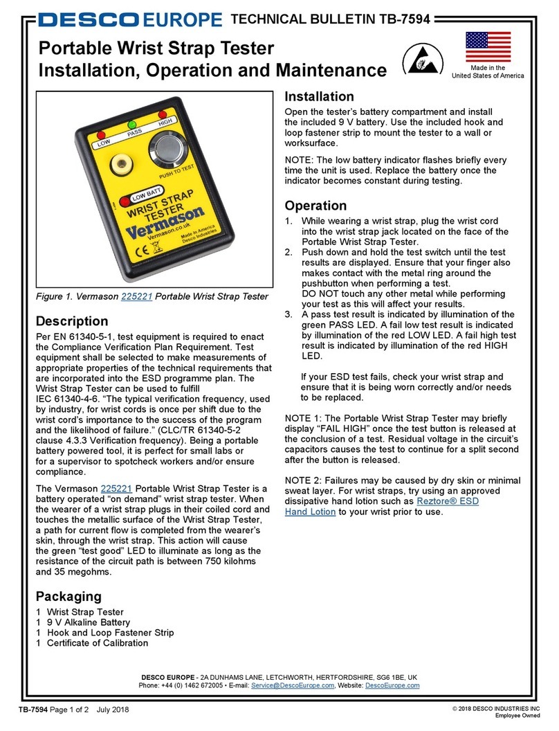
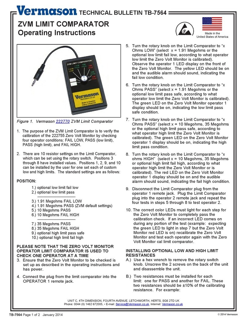
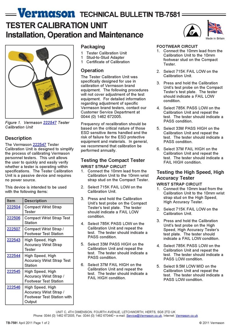
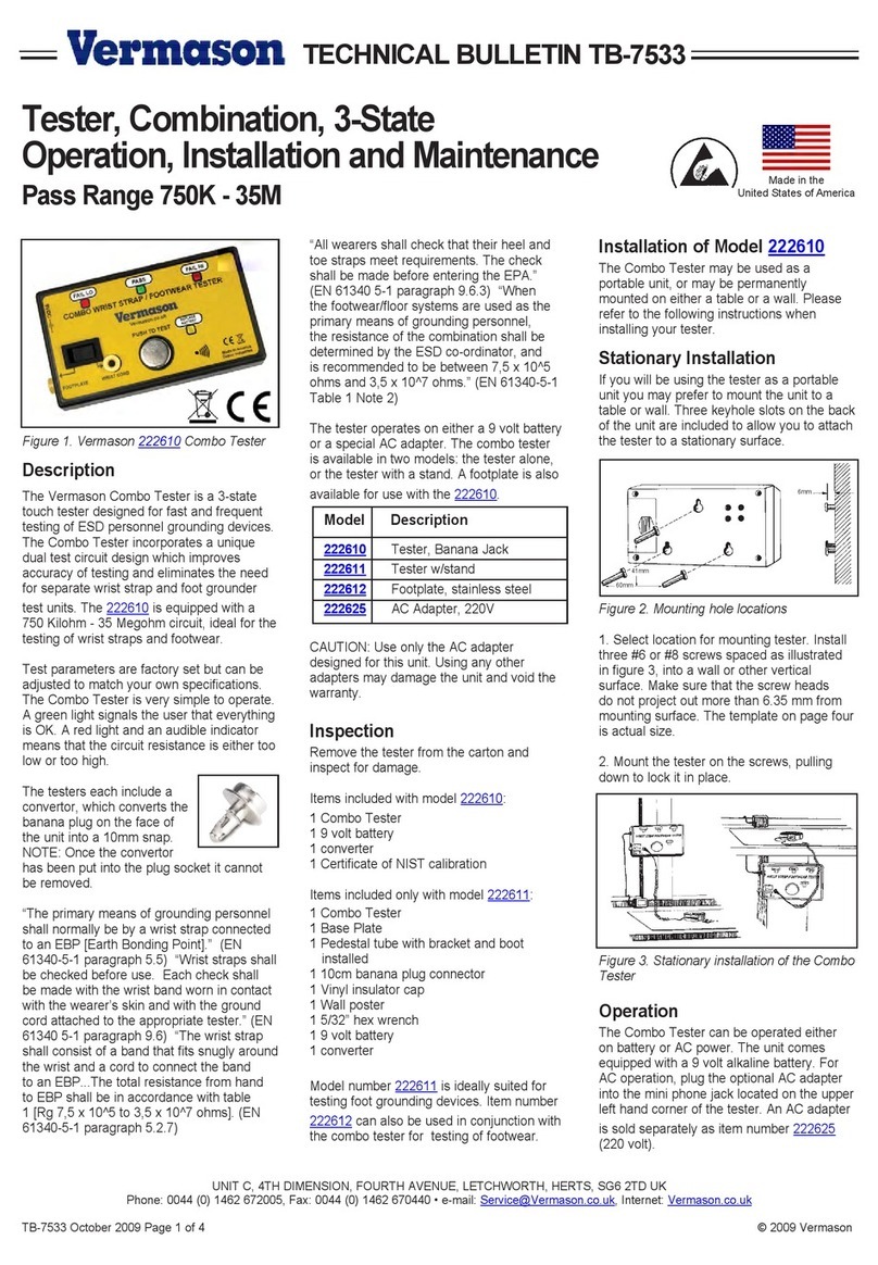
Vermason 225706 Installation and operating instructions

UNIVERSAL TEST KIT
Installation, Operation and Maintenance
UNIT C, 4TH DIMENSION, FOURTH AVENUE, LETCHWORTH, HERTS, SG6 2TD UK
Phone: 0044 (0) 1462 672005, Fax: 0044 (0) 1462 670440 • e-mail: Service@Vermason.co.uk, Internet: Vermason.co.uk
TB-7544 December 2008 Page 1 of 2 © 2008 Vermason
Description
At the heart of this kit is an electrical
resistance tester built into a 2.5kg
test probe. The kit is designed to
test the resistance to ground of
operators as well as working
surfaces, wrist straps, soldering iron
tips and other components of an
ESD Protected Area in the manner
described in EN 61340-5 A whole
workstation may be audited in 4
simple steps greatly reducing the
time to audit an ESD protected area
(EPA).
The tester has three test voltages:
24V for personnel, 100V for surfaces,
and 5V for hard ground. Four LED
indicate the range in which the
measured resistance falls. They
mark the thresholds described in EN
61340-5-1. The tester is powered by
a 9V NiMH rechargeable battery. A
charger is included in the kit along
with ground cord, insulated crocodile
clip and 10mm-stud-and-socket
converter.
The Universal Tester is CE approved
for use in medium industrial
environments. Its operating
temperature range is 10 to 35ºC.
Inspection
Remove the test unit from the carton
and inspect for shipping damages.
Each 225706 unit should include the
following:
1 Test unit, item #225706
1 Cord with two 4mm plug
terminations
1 Stud to socket adaptor
1 Insulated wide-jaw crocodile clip
1 Carry case (E9 Tool Box)
1 Battery charger
Each 225708 unit should include the
following:
1 Test unit, item #225706
1 Cylindrical probe 2.5kg
1 Cord with two 4mm plug
terminations
1 Stud to socket adaptor
1 Insulated wide-jaw crocodile clip
1 Carry case (E9 Tool Box)
1 Battery charger
Procedure
The button located on the top face
controls the tester operation. Four
different modes of operation can be
selected using this button. A buzzer
helps to select and confirm the
mode.
To audit a workstation, proceed as
follows:
1. Place the tester on the workbench.
Connect it to hard ground using
the straight lead and crocodile clip.
An electrical earth is suitable in
most cases.
2. Testing bench top resistance to
ground: depress the test button
once to select the bench top test
sample mode. The tester beeps
once, the test voltage LED’s turns
orange, confirming that the correct
mode has been selected. At first
the four LED’s flash and then one
latches to indicate the resistance
to ground value of the bench top.
The orange marking on the label
is used to read the resistance
value. The tester powers off
automatically after 4 seconds.
Alternatively, choose the
continuous test mode by rapidly
tapping the test button three
times. The continuous test mode
allows the meter to be moved and
several spots to be tested.
3. Testing of operator in-situ
resistance to ground: leave the
tester in position. The operator
wearing a wrist strap presses the
test button and keeps it depressed
until the end of the test. The test
voltage LED’s turns red and the
buzzer produces a long beep,
confirming the wrist strap test
mode. The four LED’s flash, then
one latches to indicate the
operator's resistance to ground.
Use the red marking on the label
to read the test result. Two green
LED’s and buzzer indicate that the
resistance to ground is within the
limits set by EN 61340-5-1. In
case of failure it is possible to
determine the cause by testing the
wrist strap on its own; disconnect
the cord from the grounding point
(EBP) and connect it to the 10mm
stud or 4mm socket on the side of
the tester and repeat the test.
Similarly, the cord can be tested
on its own by detaching it from the
wristband and pressing the socket
of the free end on the test button.
Operators wearing conductive
footwear can be audited in exactly
TECHNICAL BULLETIN TB-7544
Made in Britain
Figure 1. 225708 Universal Test Kit
the same manner. The tester
powers off automatically after 4
seconds, or as soon as the test
button is released.
4. Testing soldering iron tip
resistance to ground: with the
tester still in the same position and
connected to hard ground, apply
the soldering iron tip to the test
point located on the side of the
tester. Depress the test button
twice. The test voltage LED turns
green and the beeper sounds
twice to indicate 5V test voltage
and hard ground test are selected.
The LED’s flash and latch indicating
tip resistance to ground. Use the
green marking on the top label to
read resistance. Note: Soldering
irons often have a built-in
resistance of >5 . Tips of such
irons should be tested by pressing
the tip on the test button in the
manner of a wrist strap test.
Caution: do not overheat the
button as it is held in a nylon
bushing.
5. Measuring point to point
resistance: place the probe and
the tester about 80cm apart on the
surface to be tested. Disconnect
the straight lead from the earth
point and connect it to the probe.
You may then proceed as when
testing a bench top, or you can
depress the test button three
times, which leads to a continuous
test mode. It is then possible to
move the tester or probe on the
surface to take numerous
readings. To turn off the tester,
keep the test button depressed.
The tester also automatically turns
off after two minutes.
Charging the battery
The tester battery needs re-charging
when all LED’s turn on. The top left
LED flashes and the buzzer beeps.
To recharge, connect the supplied
charger to the side socket of the
tester. It takes 16 hours to charge
fully.
Note: The battery should be fully re-
charged before first use.
Limited Warranty
Vermason expressly warrants that for a period
of one (1) year from the date of purchase,
Vermason
Universal Testers
will be free of
defects in material (parts) and workmanship
(labour). Within the warranty period, a unit will
be tested, repaired or replaced at Vermason’s
option, free of charge. Call Customer Service
at
0044 (0) 1462 672005
for a Return Material
Authorisation (RMA) and for proper shipping
instructions and address. Any unit under
warranty should be shipped prepaid to the
Vermason factory. You should include a copy
of your original packing slip, invoice, or other
proof of purchase date. Warranty repairs will
take approximately two weeks.
If your unit is out of warranty, Vermason will
quote repair charges necessary to bring your
unit to factory standards. Call Customer
Service at
0044 (0) 1462 672005
for a Return
Material Authorisation (RMA) and proper
shipping instructions and address.
Warranty Exclusions
THE FOREGOING EXPRESS WARRANTY IS
MADE IN LIEU OF ALL OTHER PRODUCT
WARRANTIES, EXPRESSED AND IMPLIED,
INCLUDING MERCHANTABILITY AND
FITNESS FOR A PARTICULAR PURPOSE
WHICH ARE SPECIFICALLY DISCLAIMED.
The express warranty will not apply to defects
or damage due to accidents, neglect, misuse,
alterations, operator error, or failure to properly
maintain, clean or repair products.
Limit of liability
In no event will Vermason or any seller be
responsible or liable for any injury, loss or
damage, direct or consequential, arising out of
the use of or the inability to use the product.
Before using, users shall determine the
suitability of the product for their intended use,
and users assume all risk and liability
whatsoever in connection therewith.
Calibration
The tester needs to be calibrated at
least once a year. This may be done
using a standard calibrated
resistance decade box. If adjustment
is required, the unit needs to be sent
back to Vermason Ltd, and the
standard calibration charge applies.
Please contact us for further details.
Specifications
Resistance thresholds
Hard Ground: Low - 5Ω
High - 0.75MΩ
Wrist Strap: Low - 35MΩ
High - 100MΩ
Bench-top: High - 1000MΩ
Accuracy ±5%
Weight 2.5 ± 0.2kg
Height 150mm
Diameter 73mm
Power supply 9V PP3NiMH Battery
(cadmium-free)
Charging Time16hours at 15mA
Battery Life up to 1000 cycles
Power Off Automatic after 4
seconds / 2 minutes
depending on
selected test
Test voltage
Hard Ground: 5V
Wrist Strap: 24V
Bench-top: 100V
UNIT C, 4TH DIMENSION, FOURTH AVENUE, LETCHWORTH, HERTS, SG6 2TD UK
Phone: 0044 (0) 1462 672005, Fax: 0044 (0) 1462 670440 • e-mail: Service@Vermason.co.uk, Internet: Vermason.co.uk
TB-7544 Page 2 of 2
This manual suits for next models

1

Other Vermason Test Equipment manuals

Vermason 225221 Owner's manual

Vermason

Vermason 225221 Owner's manual

Vermason 223001 Installation and operating instructions

Vermason

Vermason 223001 Installation and operating instructions

Vermason 222700 User manual

Vermason

Vermason 222700 User manual

Vermason 222635 Installation guide

Vermason

Vermason 222635 Installation guide

Vermason ZVM LIMMIT COMPARATOR User manual

Vermason

Vermason ZVM LIMMIT COMPARATOR User manual

Vermason 222523 Installation and operating instructions

Vermason

Vermason 222523 Installation and operating instructions

Vermason 223002 Installation and operating instructions

Vermason

Vermason 223002 Installation and operating instructions

Vermason TB-7545 Service manual

Vermason

Vermason TB-7545 Service manual

Vermason 222610 Instruction Manual

Vermason

Vermason 222610 Instruction Manual

Vermason 222644 Installation guide

Vermason

Vermason 222644 Installation guide

Vermason 222696 User manual

Vermason

Vermason 222696 User manual

Vermason 222693 User manual

Vermason

Vermason 222693 User manual

Vermason 222504 Owner's manual

Vermason

Vermason 222504 Owner's manual

Popular Test Equipment manuals by other brands

STS 1656 owner's manual

STS

STS 1656 owner's manual

KYORITSU KEW 6016 instruction manual

KYORITSU

KYORITSU KEW 6016 instruction manual

Tektronix P6248 instructions

Tektronix

Tektronix P6248 instructions

KYORITSU 6011A instruction manual

KYORITSU

KYORITSU 6011A instruction manual

Fluke 154 user manual

Fluke

Fluke 154 user manual

PANCONTROL PAN VOLTFINDER manual

PANCONTROL

PANCONTROL PAN VOLTFINDER manual

Covita Smokerlyzer Micro+ quick start guide

Covita

Covita Smokerlyzer Micro+ quick start guide

GE PACE Series Technical manual

GE

GE PACE Series Technical manual

Tektronix 465B instruction manual

Tektronix

Tektronix 465B instruction manual

Infinite Pasternack PE5CK1019 user manual

Infinite

Infinite Pasternack PE5CK1019 user manual

agratronix Hay Core Sampler Operator's manual

agratronix

agratronix Hay Core Sampler Operator's manual

KYORITSU 8128 instruction manual

KYORITSU

KYORITSU 8128 instruction manual

Atlas Copco STB user guide

Atlas Copco

Atlas Copco STB user guide

Wolfgang Warmbier 7100 181 C user manual

Wolfgang Warmbier

Wolfgang Warmbier 7100 181 C user manual

Keysight Technologies 16190B Operation and service manual

Keysight Technologies

Keysight Technologies 16190B Operation and service manual

Fluke MicroScanner Series Getting started guide

Fluke

Fluke MicroScanner Series Getting started guide

Landmark TIME3200 quick start guide

Landmark

Landmark TIME3200 quick start guide

TRENDnet TC-NTP1 user guide

TRENDnet

TRENDnet TC-NTP1 user guide

manuals.online logo
manuals.online logoBrands
  • About & Mission
  • Contact us
  • Privacy Policy
  • Terms and Conditions

Copyright 2025 Manuals.Online. All Rights Reserved.