Vermason TB-7545 Service manual

TB-7545 Page 1 of 6 © 2012 VERMASON
UNIT C, 4TH DIMENSION, FOURTH AVENUE, LETCHWORTH, HERTS, SG6 2TD UK
Phone: 0044 (0) 1462 672005, Fax: 0044 (0) 1462 670440 • E-mail: Service@Vermason.co.uk, Internet: Vermason.co.uk
Surface Resistance Test Kit
Operation and Maintenance
Description
The Surface Resistance Test Kit is a portable, accurate,
and versatile instrument designed to measure point to point
resistance (Rp), resistance to ground (Rg), and surface
resistivity. It is designed to perform test methods described in
EN 61340-5-1 Annex A. Features include:
• Resistance measuring accuracy ± 10% (E11 and greater ±
20%)
• Resistance range <1.0 x 10E3 ohms to >10E12 ohms
• Open circuit voltages of 10 and 100
± 5%
• Electrification period of 15 seconds
• Electrodes 2.27 kilograms ± .06 kg with 50-70 durometer
conductive pads
In addition, the Meter measures ambient temperature and
relative humidity.
The Surface Resistance Test Kit (or its Meter) is referenced
and designed to be used to make measurements in
accordance with the test methods in EN 61340-5-1 Annex A
Resistance Measurement Test method:
• A. 1 Floor, working surface or storage rack working surface
• A.2 Seating
• A.3 Garments
• A.5.4 Gloves, finger cots and tools (Neither 20 mm plates
nor clip connectors provided)
Versatility:
Measures Rp, Rg or Resistivity (requires optional Resistivity
Attachment, item 222632)
• Quick Checks - Surface resistance exponent number
illuminates immediately i.e. 8 = 10E8 ohms or 100,000,000
ohms
• Periodic Audits of Installed Products - Surface resistance
exponent number illuminates immediately and displays
Temperature and Relative Humidity during 15 second
electrification period making numerous measurements and
calculations to the display mantissa i.e LED displays 8 and
LCD displaying 7.14 as mantissa = 7.14 x 10E8 ohms or
714,000,000 ohms
July 2012
Figure 1. Item 222630 Surface Resistance Test Kit
TECHNICAL BULLETIN TB-7545
• Laboratory Test Evaluation of Product - Display same as
above Periodic Audit
The Surface Resistance Test Kit is NIST calibrated and is
available in two models:
Model Description
222630 Surface Resistance Test Kit
222631 Meter and Attachment
A pair of Test Leads (item 222633) can be bought
separately. The Vermason 222634 replacement electrodes
can be purchased separately also.
Inspection
Remove the meter from the carton and inspect for damage.
Each Surface Resistance Test Kit should include the
following:
1 Protective carrying case
1 Meter
2 Test leads
2 2.27 kilogram electrodes
2 AA alkaline batteries
1 Certificate of NIST calibration
Properly store the Meter and component assemblies when
not in use.
ESD protective products should be tested:
A. Prior to installation to qualify for listing in user’s ESD
control plan approved ESD protective materials (see EN
61340-5 paragraph 9.3.2 Qualified protective items)
B. During initial installation
C. For periodic audits of installed products as part of EN
61340-5-1 paragraph 9 Quality responsibilities
In addition: Per EN 61340-5-2 paragraph 9.4 “When a new
EPA is established, or an existing EPA is reconfigured, it
should be thoroughly checked by the ESD co-ordinator and a
certificate … issued.”
Electrification Period
The Surface Resistance Test Kit provides the proper
electrification period of 15 to 20 seconds per ESD EN
61340-5-1, after numerous readings and calculations
are executed, then displays surface resistance mantissa
measurement (Note: most analog type meters display
measurements instantaneously).
When the Test Button is depressed, the liquid crystal display
(LCD) will indicate:
• Temperature in degrees Fahrenheit (tolerance ±5°F,
typical)
• Temperature in degrees Celsius (tolerance ±3°C, typical)
Made in the
United States of America

TB-7545 Page 2 of 6 © 2012 VERMASON
UNIT C, 4TH DIMENSION, FOURTH AVENUE, LETCHWORTH, HERTS, SG6 2TD UK
Phone: 0044 (0) 1462 672005, Fax: 0044 (0) 1462 670440 • E-mail: Service@Vermason.co.uk, Internet: Vermason.co.uk
• Humidity as percentage (from 5% - 95% tolerance, ±10
percentage points)
• Surface resistance mantissa (with exponent displayed via
LED, measurement in ohms)
The surface resistance exponent (or power of number) is
immediately illuminated and remains illuminated measuring
the range the surface resistance in ohms.
Reference Literature
In addition to those noted above:
ANSI/ESD S20.20 - Development of ESD Control Program
ESD S4.1 Work Surfaces - Resistance Measurements
These documents can be obtained directly from the ESD
Association, 7902 Turin Rd., Suite 4, Rome, NY 13440-2069,
(315) 339-6937 or www.esda.org.
Other standards are available from the agencies who
produce them. MIL-HDBK 263A, EIA-IS-5-A, ASTM-F-150,
EN 100015, and EIA-625. If you need help in obtaining
these documents, please contact our customer service
department.
Features
A
B
C
D
E
F
G
Figure 2. Features of the Surface Resistance Meter
• When battery voltage drops to approximately 2 volts, one
of the Function LED’s to the right of the red pushbutton
switch will begin to flash, indicating the need to replace
batteries.
B. Liquid Crystal Display (LCD): Mantissa is displayed via
14.3mm high liquid crystal display and provides easy to read
resistance (or resistivity) measurements.
When the Test Button is depressed, the LCD will indicate:
• Temperature in degrees Fahrenheit
• Temperature in degrees Celsius
• Humidity as percentage
• Surface resistance mantissa (with exponent displayed via
LED, measurement in ohms)
Surface resistance ohm values are expressed with a
mantissa and exponent or power of the number. For
example, if “8” is illuminated by its LED and the LCD displays
a mantissa of “7.14”, the measurement is 7.14 x 10E8 ohms
or 714,000,000 ohms
If surface is over 10E12 ohms, the following will appear:
• “1____” on the LCD display indicate Overrange or that the
reading exceeds the display capabilities
C. Test Button: This red button activates electrical power
to the Meter. The exponent or power of the number is
displayed immediately with LED illuminating number. If
“8” is illuminated, the measurement is in the 10E8 or 10E8
ohm range. To make a measurement, the button is to be
depressed for 15-20 seconds for the unit to make numerous
readings and calculations. (Testing in accordance with EN
61340-5-1 requires 15 to 20 seconds of electrification; in
contrast, most analog type meters display measurements
instantaneously.) The LCD will display temperature (F), then
temperature (C), then relative humidity, and then the surface
resistance mantissa. For example, if the LCD displays a
mantissa of “7.14”, and “8” is illuminates by its LED, the
measurement is 7.14 x 10E8 ohms or 714,000,000 ohms.
During the entire period, surface resistance exponent will be
displayed by LED illuminating number.
D. Override Test Range Voltage Button: When in the
“up” position, during resistance portion of test, Meter will
automatically switch to the correct voltage for the resistance
range. LED will illuminate noting selected voltage.
Conductive material 10E5 ohms or less should be measured
at 10 volts. Dissipative material 10E6 or greater ohms
should be tested at 100 volts. The button is a switch, which
if depressed, will override automatic voltage selection and
test will be performed at 10 volts regardless of resistance
level.
E. Jacks: One end of Test Leads has 3.5mm plug (fits
Meter left jack). One 3.5mm plug is shielded (identified by
insulated tip and barrel black lead) - see Rg test procedure:
“The sensing lead of the resistance meter shall be connected
to EPA bonding point.” One end of Test Lead has standard
banana plug (fits 2.27 Kg Electrode jack).
A. LED Displays: Surface resistance exponent is displayed
via light emitting diodes illuminating 3.17mm high number.
There are 12 LEDs displaying surface resistance exponent
measurement. They are color coded for quick checks:
Exponent Color
<3, 3 Red
4, 5 Green
6, 7, 8 Blue
9, 10, 11 Green
12, >12 Yellow
Five Function LED’s identify the measurement being
displayed (see B below).

TB-7545 Page 3 of 6 © 2012 VERMASON
UNIT C, 4TH DIMENSION, FOURTH AVENUE, LETCHWORTH, HERTS, SG6 2TD UK
Phone: 0044 (0) 1462 672005, Fax: 0044 (0) 1462 670440 • E-mail: Service@Vermason.co.uk, Internet: Vermason.co.uk
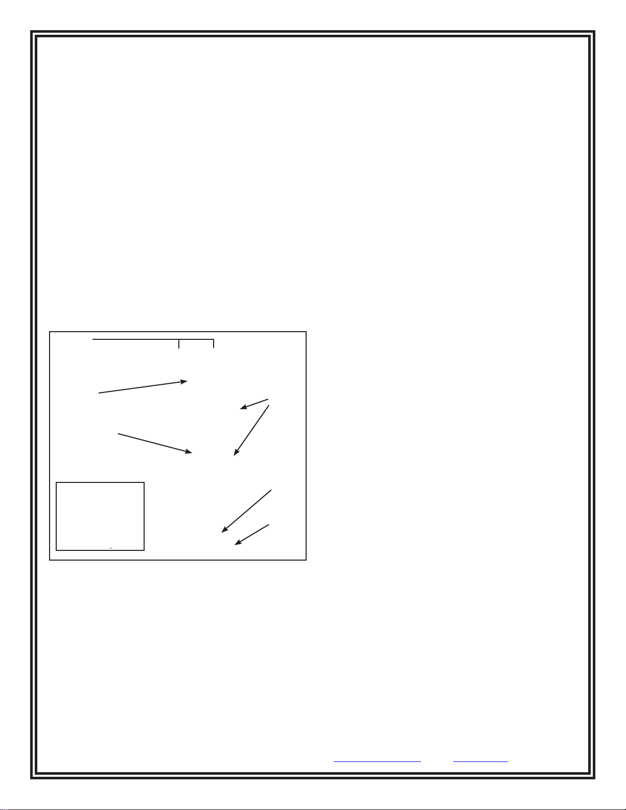
F. AA Battery Compartment.
G. Resistivity Parallel Attachment with Electrodes. (optional
Item number 222632)
Cleaning
Clean the conductive pads of electrodes with a minimum
70% isopropanol-water solution.” Make sure they are dry
prior to use.
See specific product test standard for laboratory test
specimen cleaning instructions. Generally, the test
specimens and electrodes should be cleaned twice with a
minimum 70% isopropanol-water solution using a clean,
low-linting cloth each time.” (Note: then conditioned for 72
hours, minimum)
For installed product periodic audits, do not clean surfaces.
However, if any measurements lie outside the acceptable
range, clean the surface and re-test. (Note: for working
surfaces, use Vermason Reztore™ Antistatic Surface
and Mat Cleaner (item 229020) or other ESD cleaner not
containing silicone. Be sure the surfaces dry before testing.
Periodic maintenance - The area surrounding the cable jacks
at the top end of the meter should be wiped with a clean
cloth moistened with alcohol to remove skin oils that will
accumulate and affect the accuracy at high resistances. The
frequency of cleaning will depend on usage; once a month
would be a good starting point. Other items that should
also be cleaned in this fashion are the cable jackets and the
resistivity attachment, if included.
Power Requirements
The Meter is powered by two replaceable alkaline AA
batteries.
Test Procedure
General Guidelines:
• Use both 2.27 Kg Electrodes for Rg
• Use one 2.27 Kg Electrode with lead to grounded EPA
bonding point for Rp (note: EPA bonding points are usually
snaps installed on the material or workstation)
• Use optional Resistivity Attachment (removing leads &
Electrodes) for Resistivity measurements
• Ensure that item being measured is electrically isolated
(i.e. placed on an insulative surface) or Meter may
measure lower resistance path. Lay item on an insulating
support (>10E12 ohms) avoiding contact with the table.
• Ensure that test leads are separated or Meter may
measure lower resistance path
• When using 2.27 kg Electrodes:
• Place no closer than 5 cm from edge of surface being
measured
• Place no closer than 7 cm to any EPA bonding point
• Place 2.27 kg Electrodes about 25 cm apart for Rp
• Preferred placements include: most commonly used
surface portion, most worn, center, furthest from EPA
bonding point.
• For Rg, connect the sensing lead with shielded plug to
grounded EPA bonding point
• If surface has sections (like floor tiles or garment panels),
for Rp place a 2.27 kilogram electrode on different sections
• Clean surface for Laboratory test, but do not initially clean
surface for installed products (if fails, clean and retest)
Laboratory Test Procedure Guideline
For laboratory test of ESD Working surfaces, Floor Materials,
Footwear, Garments, or Seating, best advice is to follow test
methods of Annex A of EN 63140-5-1.
• The test specimens and electrodes should be cleaned
twice with a minimum 70% isopropanol-water solution
using a clean, low-linting cloth each time)
• Environmental chamber (Control relative humidity to 12
±3% RH and 50 ±3% RH and temperature to 23 ±2° C)
• Specimen support surface (greater than 1012 ohms such as
PMMA, PTFE or polycarbonate)
• Specimen Pre-Conditioning (23 ±2 degrees C; 3
specimens at 12 ±3% relative humidity for up to 48 hours
minimum, and 3 specimens at 50 ±3% relative humidity for
up to 48 hours minimum
• Measurement of point-to-point resistance shall be
performed according to 2.1.2.3 of IEC 61340-4-1 in a
minimum of three locations for point-to-point resistance,
and a minimum of one location per square metre for
large areas for qualification testing, for surface-to-EPA
ground resistance. Care shall be taken to include, when
applicable, resistance between separate tiles.
• Reporting Test Results
• Minimum, median and maximum readings for both
resistance-to-ground and point-to-point resistance in ohms
at low relative humidity
• Minimum, median and maximum readings for both
resistance-to-EPA bonding point and point-to-point
resistance in ohms at moderate relative humidity
• Temperature
• Relative humidity
• Actual duration of conditioning
• Test equipment used
Periodic Audit of Installed Product Test
Procedure Guideline
Measure Rg Resistance to Ground
Test Procedure:
• The material shall be tested without cleaning of the surface
with liquid cleaning agents. Loose dust may be removed
by gentle brushing or by blowing with clean, dry air.
• Remove from the surface only those items that might
interfere with the test.
• ESD sensitive devices shall also be removed
• Clip the sensing test lead with shielded plug to grounded
EPA bonding point
• Use one 2.27 kg Electrode on other test lead and place
Electrode the farthest convenient point on the surface
• Press button and hold Test Button until measurement is
displayed
• Perform additional measurements placing Electrode on the
most commonly used or most worn area

TB-7545 Page 4 of 6 © 2012 VERMASON
UNIT C, 4TH DIMENSION, FOURTH AVENUE, LETCHWORTH, HERTS, SG6 2TD UK
Phone: 0044 (0) 1462 672005, Fax: 0044 (0) 1462 670440 • E-mail: Service@Vermason.co.uk, Internet: Vermason.co.uk
• Per EN 61340-5-1 paragraph 10.1 “All audit
measurements shall be carried out under the normal
operating environment, and the temperature and relative
humidity shall be recorded”
If measurement is outside acceptable limits, clean surface &
retest to determine if cause of failure is insulative dirt layer
or the ESD protective product. Note: Use an ESD cleaner
containing no insulative silicone (i.e. Reztore™ Antistatic
Surface and Mat Cleaner)
Figure 3. Setting up for Rg testing
Periodic Audit of Installed Product Test
Procedure Guideline
Measure Rp Resistance Between Two Points
on the Surface
• The material shall be tested without cleaning of the surface
with liquid cleaning agents. Loose dust may be removed
by gentle brushing or by blowing with clean, dry air.
• Remove from the surface only those items that might
interfere with the test.
• ESD sensitive devices shall also be removed
• Use two 2.27 kg Electrodes, place in the most commonly
used portion of the surface about 25 cm apart (5 cm from
any edge, 7 cm from any EPA bonding point)
• Press button and hold Test Button until measurement is
displayed
• If the most used portion is not obvious, use two points near
the center of the surface
• Per EN 61340-5-1 paragraph 10.1 “All audit measurements
shall be carried out under the normal operating
environment, and the temperature and relative humidity
shall be recorded”
If measurement is outside acceptable limits, clean surface
and retest to determine if cause of failure is insulative dirt
layer or the ESD protective product. Note: Use an ESD
cleaner containing no insulative silicone (i.e. Reztore™
Antistatic Surface & Mat Cleaner)
Figure 4. Setting up for Rp testing.
10"
Recommended Frequency of Periodic Checks
of Installed Products
Note: The frequency of periodic checks is normally specified
in corporate operating procedures. The frequency of testing
is driven by the amount of risk exposure that can occur
between checks. For, example, what is the quantity of
product handled between test periods?”
• Working surface - Per EN 61340-5-1 paragraph 10.1
“These audits shall be performed at intervals not
exceeding those defined by the ESD co-ordinator.” (Users
typically perform these quarterly.)
• Non-permanent Footwear - users typically perform a lot
sampling at incoming inspection.
• Floor - Per EN 61340-5-1 paragraph 10.1 “These audits
shall be performed at intervals not exceeding those defined
by the ESD co-ordinator.” (Users typically perform these
quarterly.)
• Seating - Per EN 61340-5-1 paragraph 10.1 “These audits
shall be performed at intervals not exceeding those defined
by the ESD co-ordinator.” (Users typically perform these
quarterly.)
• Non-disposable Garments - Six-monthly check
(particularly sleeve-to-sleeve resistance).
Surface Resistivity
Theoretically Resistivity is 10 times greater than Resistance,
i.e. a material that measures 10E7 ohms Rp, Surface
Resistivity should measure 10E8 ohms/square.*
Ref: ESD S11.11 paragraph 12.0 Conversion to Resistivity
states, “When it is appropriate to convert a resistance
obtained by this test method to an equivalent resistivity in
ohms per square, multiply the resistance measurements
obtained by this method by 10. The conversion factor of 10 is
derived from the geometry of the electrode assembly.”
No conversion is required with the Surface Resistance Test
Kit. The Meter incorporates provision to install optional
Resistivity Attachment which has parallel electrodes
on bottom of the unit to make direct surface resistivity
measurements. These parallel electrodes allow for
measurement of resistivity or when quick testing without the
use of 2.27 kilogram electrodes is desired.

TB-7545 Page 5 of 6 © 2012 VERMASON
UNIT C, 4TH DIMENSION, FOURTH AVENUE, LETCHWORTH, HERTS, SG6 2TD UK
Phone: 0044 (0) 1462 672005, Fax: 0044 (0) 1462 670440 • E-mail: Service@Vermason.co.uk, Internet: Vermason.co.uk
*Note: Per EN 61340-5-2 paragraph 5, “point-to-point
resistance has been discussed, rather than the surface
and volume resistivity which was found in previous
standards and reports. This change has been made to
cater for non-homogeneous materials, which are becoming
increasingly common in these applications, as well as ease
of measurement.”
Battery Life: Approximately 1,500 measurements. LED and
decimal will blink when battery level falls below 2.00V.
Resistivity Electrodes: Two parallel conductive silicone
rubber electrodes (optional item)
External Electrodes: Two 2.27 kilogram weighted electrodes,
6.35 cm in diameter, complies with ESD-S4.1
Display: One 3.5 digit 12.7 mm Liquid Crystal Display
(LCD) Display & seventeen Light Emitting Diodes (LED’s)
illuminated exponent numbers and function being performed.
*Accuracy: Resistance measurements within ± 10% (E11
and greater ± 20%), complies with ESD-S4.1. Open circuit
voltages of 10 volts ± 5% and 100 volts ± 5% exceeds
requirements of ESD-S4.1
Meter Weight: 439 grams
Dimensions: 203 mm L x 109 mm W x 41 mm H
Test Switch: Press the red test button for 15-20 second
electrification period. Meter will immediately display surface
resistance exponent via LED. LCD will display temperature
(both Fahrenheit & Celsius), then humidity, and after taking
numerous readings and making numerous calculations
display surface resistance mantissa.
Note: Reporting test results, you may want to record the
resistance, humidity, temperature, and test voltage.
Maintenance
Your Surface Resistance Test Kit will require little
maintenance, and there are no user serviceable parts. If your
Meter requires service beyond cleaning the
Electrodes or replacing the batteries, please contact the
factory.
This product utilizes a high frequency switching circuit to step
up the 3 volts from the batteries to the 100 volt test level.
Some users are able to discern a slight hum or buzzing.
This is perfectly normal and should not be considered a flaw
or defect.
Calibration*
The Surface Resistance Test Kit is calibrated to NIST
traceable standards. Most users require calibration annually.
Please call our Customer Service Department at 00 44
(0) 1892-665313 for details. In-house calibration can be
performed by using 1% resistors in each of the meter
ranges. Simply attach the resistors to the enclosed cords
using grounding clips and recording the meter display. Keep
the cords separated. Should adjustment be necessary, it
is recommended that the unit be returned to the factory as
access to internal adjustments requires special equipment
and test cables.
EQUIPMENT:
• Digital Multimeter - accurate to 1.25% @ 10VDC and
100VDC
• Fixed Decade Box value 10E3 - 10E12 - accurate to
±2.5%, except at 10E11 and 10E12 (±5%)
• Thermometer - accurate to ±1°F
• Humidity meter - accurate to 2%
• Test leads
• 99% Isopropyl alcohol and cleaning wipes
SET UP:
A .Test Area - Area needs to be free of any high voltage
transformer or power supply. Not under any type of
fluorescent lighting or high power lighting.
B. Worksurface - needs to be covered with conductive mat
at 1.0 x 10E3 or less, connected to earth ground.
C. Technician - needs to be grounded with zero ohms
resistor to earth ground.
D. Decade Box - needs to be grounded to earth ground.
*Accuracy is measured after normalizing the instrument at
70-80 °F and 30-50% RH for a minimum of 4 hours.
NORMALIZATION OF SURFACE RESISTANCE TESTER
Temperature inside testing area needs to be 75°F @
±6.6% 40% to 60% RH. Testers need to stay at constant
temperature 75°F @ ±6.6% for about 2 hours for proper
reading. Testers cannot be inside objects, enclosed boxes,
containers or cases unit is supplied with (temperature
inside case will differ from outside temperature, cases will
act like an insulator to the Testers), Testers will have to be
stationary in testing area for about 2 hours with no dramatic
temperature changes.
TESTING OF SURFACE RESISTANCE TESTER
• When testing use only the leads supplied with the tester.
DO NOT TEST WITH RESISITIVITY ATTACHMENT,
Resitivity Attachment will give a much higher reading and
is only designed for spot checking.
• With 10V/AUTO switch down, press TEST button - voltage
between the two leads should be 10V ±5%
• With 10V/AUTO switch up, press TEST button - voltage
between the two leads should be 100V ±5%
• Using the cleaning wipes and 99% isopropyl, clean around
banana jack and mono jack where leads connects to, oil
from human fingers can alter accuracy.
• Make sure 10V/AUTO switch is set to AUTO (switch up).
Testing each decade starting from 1.0 x 10E12 and down,
never start from 1.0 x 10E3.

TB-7545 Page 6 of 6 © 2012 VERMASON
UNIT C, 4TH DIMENSION, FOURTH AVENUE, LETCHWORTH, HERTS, SG6 2TD UK
Phone: 0044 (0) 1462 672005, Fax: 0044 (0) 1462 670440 • E-mail: Service@Vermason.co.uk, Internet: Vermason.co.uk
Temperature
Fahrenheit = 75°F ±6.6% Celsius
= 23.8°C ±10.2%
Relativity Humidity ±10 Digits
A. 1.0 x 10E12
+ 20% LED = 12 Yellow Mantissa 1.20
0% LED = 12 Yellow Mantissa 1.00
- 20% LED = 11 Yellow Mantissa 8.00
B. 1.0 x 10E11
+20% LED = 11 Yellow Mantissa 1.20
0% LED = 11 Yellow Mantissa 1.00
-20% LED = 10 Green Mantissa 8.00
C. 1.0 x 10E10
+10% LED = 10 Green Mantissa 1.10
0% LED = 10 Green Mantissa 1.00
-10% LED = 9 Green Mantissa 9.00
D. 1.0 x 10E9
+10% LED = 9 Green Mantissa 1.10
0% LED = 9 Green Mantissa 1.00
-10% LED = 8 Blue Mantissa 9.00
E. 1.0 x 10E8
+10% LED = 8 Blue Mantissa 1.10
0% LED = 8 Blue Mantissa 1.00
-10% LED = 7 Blue Mantissa 9.00
F. 1.0 x 10E7
+10% LED = 7 Blue Mantissa 1.10
0% LED = 7 Blue Mantissa 1.00
-10% LED = 6 Blue Mantissa 9.00
G. 1.0 x 10E6
+10% LED = 6 Blue Mantissa 1.10
0% LED = 6 Blue Mantissa 1.00
-10% LED = 5 Green Mantissa 9.00
H. 1.0 x 10E5
+10% LED = 5 Green Mantissa 1.10
0% LED = 5 Green Mantissa 1.00
-10% LED = 4 Green Mantissa 9.00
I. 1.0 x 10E4
+10% LED = 4 Green Mantissa 1.10
0% LED = 4 Green Mantissa 1.00
-10% LED = 3 Red Mantissa 9.00
J. 1.0 x 10E3
+10% LED = 3 Red Mantissa 1.10
0% LED = 3 Red Mantissa 1.00
-10% LED = <3 Red Mantissa <0.90
Specifications
Ranges:
1 x 10E3 - 10E12 ohms @ 10 Volts
1 x 10E6 - 1 x 10E12 ohms @ 100 Volts
Power Supply: Two AA alkaline batteries
Limited Warranty
Vermason expressly warrants that for a period of one (1) year
from the date of purchase, Vermason Surface Resistance
Test Kits will be free of defects in material (parts) and
workmanship (labour). Within the warranty period, a unit will
be tested, repaired or replaced at Vermason’s option, free of
charge. Call Customer Service at
0044 (0) 1462 672005
for a
Return Material Authorisation (RMA) and for proper shipping
instructions and address. Any unit under warranty should be
shipped prepaid to the Vermason factory. You should include
a copy of your original packing slip, invoice, or other proof of
purchase date. Warranty repairs will take approximately two
weeks.
If your unit is out of warranty, Vermason will quote repair
charges necessary to bring your unit to factory standards.
Call Customer Service at
0044 (0) 1462 672005
for a Return
Material Authorisation (RMA) and proper shipping instructions
and address.
Warranty Exclusions
THE FOREGOING EXPRESS WARRANTY IS MADE IN LIEU
OF ALL OTHER PRODUCT WARRANTIES, EXPRESSED AND
IMPLIED, INCLUDING MERCHANTABILITY AND FITNESS
FOR A PARTICULAR PURPOSE WHICH ARE SPECIFICALLY
DISCLAIMED. The express warranty will not apply to defects or
damage due to accidents, neglect, misuse, alterations, operator
error, or failure to properly maintain, clean or repair products.
Limit of Liability
In no event will Vermason or any seller be responsible or liable
for any injury, loss or damage, direct or consequential, arising
out of the use of or the inability to use the product. Before using,
users shall determine the suitability of the product for their
intended use, and users assume all risk and liability whatsoever
in connection therewith.
Table of contents
Other Vermason Test Equipment manuals

Vermason
Vermason 222504 Owner's manual

Vermason
Vermason 222523 Installation and operating instructions

Vermason
Vermason 222610 Instruction Manual

Vermason
Vermason 222696 User manual

Vermason
Vermason 222700 User manual

Vermason
Vermason 222693 User manual

Vermason
Vermason 223001 Installation and operating instructions

Vermason
Vermason 225221 Owner's manual

Vermason
Vermason 222644 Installation guide

Vermason
Vermason 225706 Installation and operating instructions