22003064
6. Remove the left and right inner walls (Fig. 6, Items 5,
13) of the stove. Hex bolts at the top and bottom hold them
in place. These walls have rope gaskets, forming seals
between the inner walls and the outer walls of the stove.
With the bolts removed, pry the forward edges of the in-
ner walls toward the center of the rebox. The panels will
come out through the front opening or through the griddle
opening.
7. Use the Allen wrench to loosen the Allen bolt (Fig. 6,
Item 14) in the base of the damper handle (Item 15). Leave
the loosened bolt in the handle to keep from misplacing it.
Pull the handle off the J-shaped damper handle rod. (Fig.
6, Item 16) Push the rod into the rebox.
8. With the damper open, remove the damper activating
link (Fig. 6, Item 17) on the left side of the rebox. This
piece is shaped like a hockey stick and has a hole in each
end. The forward hole engages the damper activating arm
and the rear hole engages the damper torsion bar (Item
7).
9. If the stove has a steel rear outer heat shield, remove
it. Four bolts hold it to spacers threaded to the back of the
stove. Leave the spacers in place.
10. A hex bolt (Fig. 6, Item 1) on each side of the stove
back holds the upper reback assembly (Item 6) in place.
Remove and discard these bolts. Keep the washers. From
inside the rebox, pull the right-hand end of the upper
reback toward yourself; you may need to use a at screw-
driver to pry the reback loose from the panel behind it.
11. Remove the catalyst access panel (Item 18), part
of the refractory package (Item 3) that houses the catalytic
combustor (Item 19). It is friction-t into place. Wiggle it
slightly to loosen it. Notice its positioning; this will be im-
portant when you install the catalyst in the new refractory
package.
12. Remove the catalytic burner carefully, inspect and clean
it, and set aside. To clean it, take outdoors and blow gently
through it. Do not use compressed air; do not run anything
through the honeycomb. The catalyst is a thin coat of plati-
num on the ceramic honeycomb, and friction can remove
the coating, shortening the unit’s life. Check your Encore
owner’s manual for details on evaluating the catalyst.
13. Remove the refractory package. Pull it straight toward
yourself, and slide it out through the front door opening.
Put it in a closed bag to contain any airborne dust.
14. On the outer back side of the stove, there is a steel
plate (Fig. 6, Item 23) held in place with two Phillips bolts.
Remove the bolts and the steel plate.
15. Behind the steel plate, there is a secondary probe as-
sembly (Item 22). This consists of a probe and a bimetal
coil secured by a phillips screw. There is a slender steel
rod between the end of the coil and a pivoting valve plate
(Item 21). Remove the phillips screw and pull the coil and
probe partway out of the stove back. When the probe is
halfway out of the stove back (about 1” showing), remove
the slender rod from the tab at the end of the coil. Leave
the rod hanging from its tab on the secondary valve. Leave
the secondary valve, Item 21, in place.
16. Remove the two steel heat deectors (Items 4, 20) from
back of the rebox; these were originally on each side of
the refractory package.
Re-Assembly
Use a hammer and a cold chisel or old screwdriver to re-
move any remaining cement from the upper rear area of
the rebox, where the upper reback attaches. Remove
any debris from the stove’s back chamber.
1. Remove the catalyst access panel (Fig. 6, Item 18) from
the new refractory chamber. Install the chamber in the back
of the stove, with the opening facing forward.
2. Reinstall the two steel heat deectors, (Fig. 6, Items 4,
20) one on each side of the refractory package. The shorter
arm of each goes at the bottom of the deector, with the
longer arm against the cast iron back sides of the rear
chamber. These deectors provide important protection
from the very hot gases leaving the refractory chamber.
3. Slide the catalytic combustor (g. 6, Item 19) into place
within the refractory chamber. Notice that the openings of
the honeycomb must be on the top and bottom horizontal
surfaces of the combustor, as shown in Figure 6.
4. Install the refractory access panel in front of the catalyst.
It friction-ts into place.
5. Install the new upper reback assembly. Swing its left
end (with the damper torsion bar protruding) into the re-
box and place it on its supports. Swing the right end into
position, and secure the assembly with two new 1/4”-
20 x 1¹⁄₂” bolts. Be sure to use the original washers. Do
not overtighten these bolts, especially if the stove back is
enamelled. Overtightening these bolts can cause excess
tension on them and/or the upper reback assembly.
6. Join the rear hole in the damper activating link (the
‘hockey stick’) (Fig. 6, Item 17) to the end of the damper
torsion bar. (Fig. 6, item 7) Note the positioning of the link;
the blade of the ‘hockey stick’ goes toward the front of the
stove, aiming downward. This is the only position in which
the link will close and lock the damper.
ST645
Encore
remove fireback
3/01
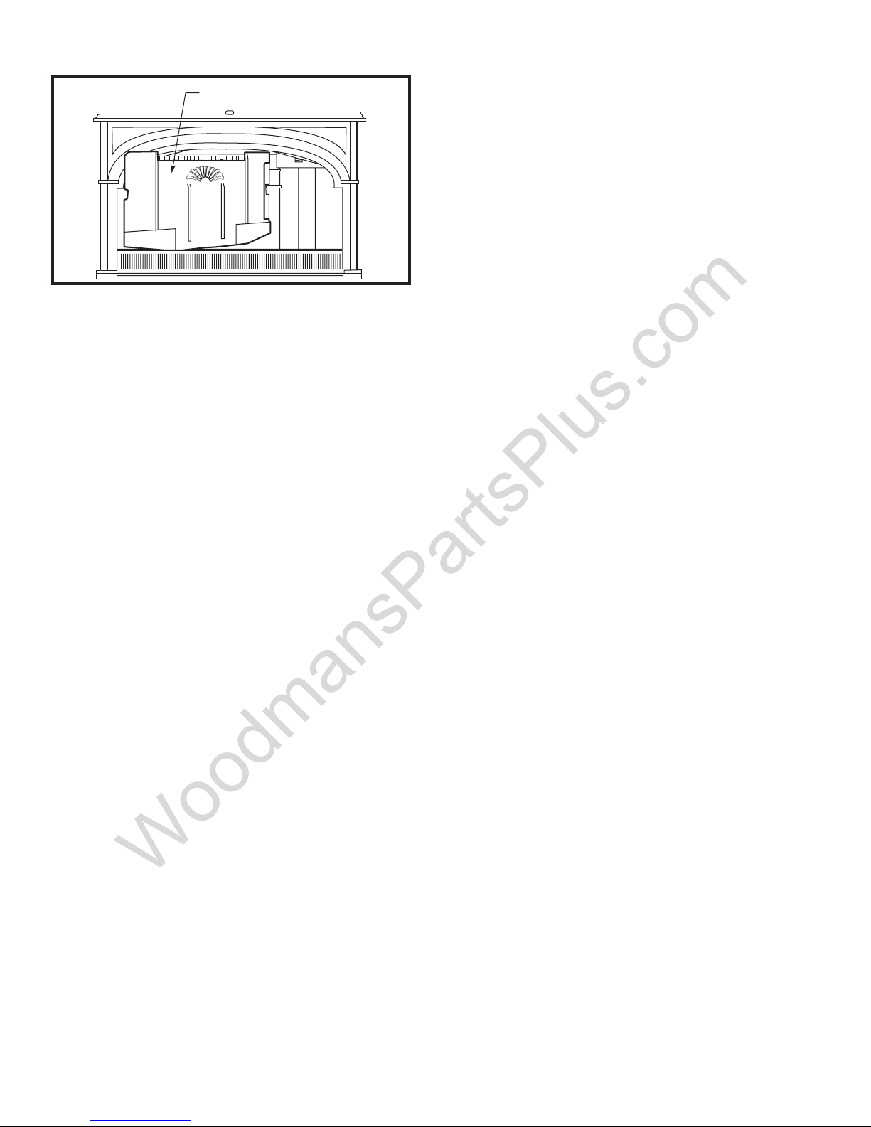
Fireback
ST645
Fig. 3 Lift out the lower reback.


