SCAN Andersen 4-5 User manual

Scan Andersen 4-5
Scan Andersen 4-5 S
UK - Installation and Operating Instructions 3
Andersen 4-5
Manual Version P00
The manuals which are enclosed with the product must be kept throughout the product’s entire service life.
ScanAndersen 4 - 5 BP
(Convection model) ScanAndersen 4 - 5 S BP
(Soapstone model)

2

3
English
Table of contents
Installation manual with technical data
1.0 Relationship to the authorities..................... 3
2.0 Technical data ............................................ 3
3.0Safety ......................................................... 7
4.0 Installation / Conversion to ScanAndersen......7
5.0Daily use.................................................... 12
6.0 Service....................................................... 14
7.0Maintenance .............................................. 15
8.0Operational problemes -
troubleshooting .......................................... 15
9.0 Optional Equipment / Delivery units ......... 16
10.0 Guarantee terms...................................... 16
1.0 Relationship to the
authorities
Installation of a fireplace must be according to local codes and
regulations in each country.
All local regulations, including those that refer to national and
European standards, shall be complied with when installing
the product.
Before use read the Installation and Operating Instructions
carefully. We recommend that the installed product be
inspected by a qualified professional before use.
A heat-resistant rating plate is attached to the rear of the
heat shield. This contains information about identification and
documentation for the product.
2.0 Technical data
Material: Cast iron
Finish: Black paint
Fuel: Wood
Log length, max.: 30 cm
Flue outlet: Top, rear
Flue pipe dimension: Ext: Ø 125 mm/Ø130 mm
Weight with convection panels: Approx. 94 kg
Weight with soapstone panels: Approx. 178 kg
Dimensions, distances: See fig. 1
Technical data according to EN 13240:
Nominal heat output: 4 kW
Recommended chimney draught: 13 Pa
Efficiency: 77%
CO emission (13% O2): 0.09%
CO emission (13% O2): 1178 mg/Nm3
chimney temperature: 269 oC
Operational type: Intermittent
Intermittent combustion in this context means normal use of
the fireplace, i.e. fuel is added as soon as the fuel has burnt
down to a suitable amount of embers.
The lot number and year are
marked on a label on all our
products. Write this number in the
place indicated.
If you need to contact your dealer,
you must always provide the serial
number and guarantee card/
receipt for the guarantee to be
valid.
Throw away the Jøtul F 145 / F 145 S
installation manual included with the
burn chambre. Use the manual that
comes with the conversion kit from
F145 to S A 4-5

4
English
Scan Andersen 4-5 / Scan Andersen 4-5 S
Fig 1a
Scan Andersen 4-5 S (Soap stone model)
Scan Andersen 4-5 (Convection model)
474
164
457
758
*651
400
457
*651
821
164
400
Y
** 850
X
Min. measurments floor plate
X/Y = according to national laws
and regulations.
* Center rear smoke outlet
** Minimum distance to furniture/combustible
material.
900209-P00
536

5
English
Minimum distance to combustible wall
Fig. 1b
Scan Andersen 4-5 Scan Andersen 4-5
Minimum distance to combustible wallScan Andersen 4-5
S
Scan Andersen 4-5 S
Inclusive rear optional convection shield
(part no. 50013025)
900209-P00
150
314
150
407
314
150
407
150
300
464
300
300
532 537
300
532
300
568 545
300
568
300
464
300
Inclusive rear optional convection shield
(part no. 50013027)

6
Minimum distance to incumbent firewall
Scan Andersen 4-5
Scan Andersen 4-5 S
Fig. 1c
All dimensions are with semi-insulated/shielded fuel pipe all the way down to the product 900209-P00
Combustible wall
Firewall
724
214
50
** 850
1252
214
50
50
891
712
100
332
287
214
50
** 850
1252
214
50
899
50
796 782
295
100
368
Minimum distance to incumbent firewall
All dimensions are with semi-insulated/shielded fuel pipe all the way down to the product
English

7
3.0 Safety
NB! We recommend that installation be carried out by a
qualified installer, to ensure that the product delivers maximum
performance and safety.
Any modifications to the product by the distributor, installer
or consumer may result in the product and safety features not
functioning as intended. The same applies to the installation
of accessories or optional extras that are not supplied by the
fireplace manufacturer. This may also be the case if parts that
are essential to the functioning and safety of the fireplace
have been disassembled or removed. In all these cases, the
manufacturer is not responsible or liable for the product and
the warranty shall become null and void.
The Clean Air Act
“The Clean Air Act 1993 and Smoke Control Areas”
Under the Clean Air Act local authorities may declare the
whole or part of the district of the authority to be a smoke
control area. It is an offence to emit smoke from a chimney of
a building, from a furnace or from any fixed boiler if located in a
designated smoke control area. It is also an offence to acquire
an “unauthorised fuel” for use within a smoke control area
unless it is used in an “exempt” appliance (“exempted” from
the controls which generally apply in the smoke control area).
The Secretary of State for Environment, Food and Rural
Affairs has powers under the Act to authorise smokeless
fuels or exempt appliances for use in smoke control areas in
England. In Scotland and Wales this power rests with Ministers
in the devolved administrations for those countries. Separate
legislation, the Clean Air (Northern Ireland) Order 1981,
applies in Northern Ireland. Therefore it is a requirement that
fuels burnt or obtained for use in smoke control areas have
been “authorised” in Regulations and that appliances used to
burn solid fuel in those areas (other than “authorised” fuels)
have been exempted by an Order made and signed by the
Secretary of State or Minister in the devolved administrations.
Further information on the requirements of the Clean Air Act
can be found here : http://smokecontrol.defra.gov.uk/
Your local authority is responsible for implementing the Clean
Air Act 1993 including designation and supervision of smoke
control areas and you can contact them for details of CleanAir
Act requirements”.
Your local authority is responsible for implementing the Clean
Air Act 1993 including designation and supervision of smoke
control areas and you can contact them for details of CleanAir
Act requirements”
3.1 Fire Prevention Measures
• There is a certain element of danger every time you use
your fireplace. The following instructions must therefore be
followed:
• The minimum safety distances when installing and using the
fireplace are given in fig. 1.
• Ensure that furniture and other flammable materials are not
too close to the fireplace. Flammable materials should not be
placed within 850mm of the fireplace.
• Allow the fire to burn out. Never extinguish the flames with
water.
• The fireplace becomes hot when lit and may cause burns if
touched.
• Only remove ash when the fireplace is cold. Ash can
contain hot embers and should therefore be placed in a
non-flammable container.
• Ash should be placed outdoors or be emptied in a place
where it will not present a potential fire hazard.
In case of chimney fire:
• Close all hatches and vents.
• Keep the firebox door closed.
• Check the loft and cellar for smoke.
• Call the fire service.
• Before use after a fire an expert must check the fireplace
and the chimney in order to ensure that it is fully functional.
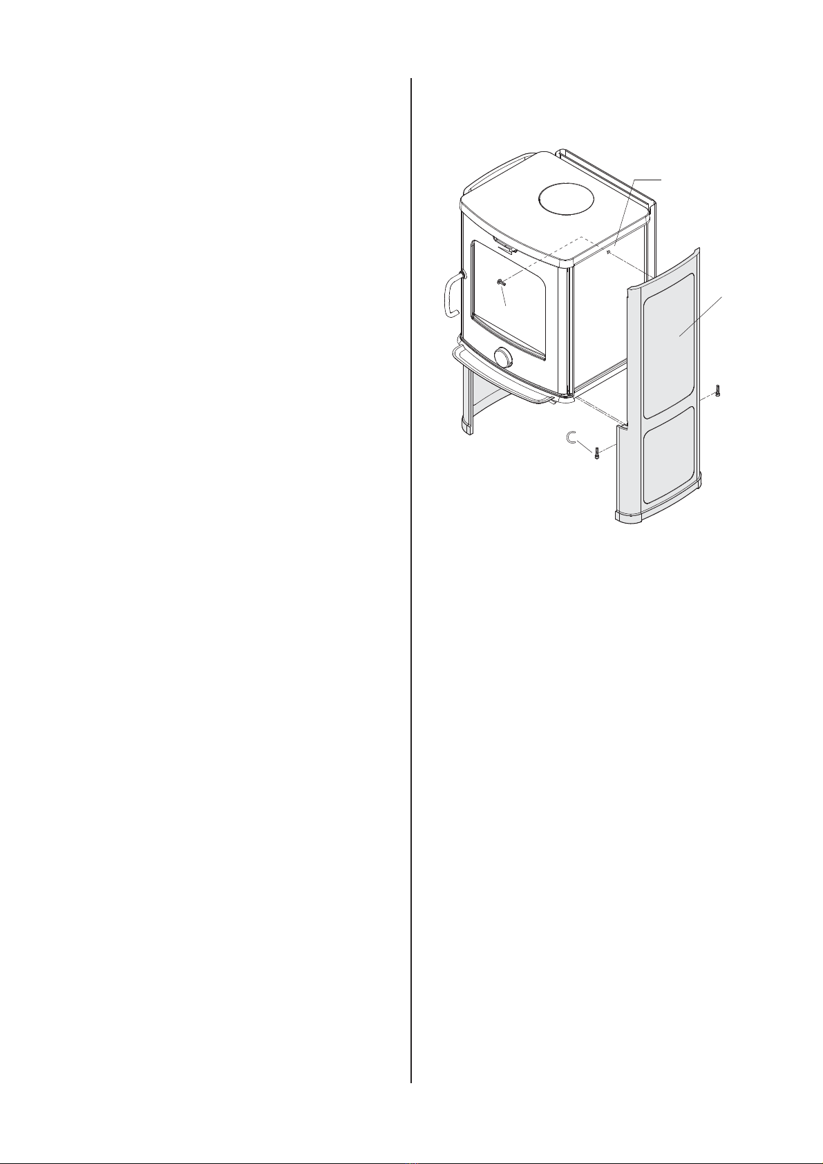
4.0 Installation
N.B. Check that the fireplace is free of any damage prior to
commencing installation.
The product is heavy! Make sure you have assistance when
erecting and installing the fireplace.
4.1 Floor
Foundation
Youneedtomakesurethe foundationissuitablefora fireplace.
See “2.0 Technical Data” for specified weight.
Combustible floor protection
If the fireplace is to be mounted on a combustible floor, cover
the floor under and in front of the fireplace with a plate made of
metal or other non-combustible material. The recommended
minimum thickness is 0,9 mm (fig. 1a).
Any flooring made of combustible material, such as linoleum,
carpets, etc. must be removed from under the floor plate.
Requirement for protecting combustible flooring in front of
fireplace
The front plate must be in accordance with national laws and
regulations.
Contact your local building authorities regarding restrictions
and installation requirements.
4.2 Wall
Minimum distance to combustible wall
For distance to combustiblewall see fig. 1b.
Minimum distance to incumbent
firewall
For distance to incumbent firewall see fig. 1c.
Firewall requirement
The firewall must be at least 100 mm thick and be made of
brick, concrete-stone or light concrete. Other materials and
constructions with satisfactory documentation may also be
used.
English

8
English
4.3 Chimneys and flue pipes
• The fireplace can be connected to a chimney and flue
pipe approved for solid fuel fired appliances with flue gas
temperatures specified in «2.0 Technical data”.
• The chimney’s cross-section must be at least as big as the
flue pipe’s cross-section. See «2.0 Technical data» when
calculating the correct chimney cross-section.
• Several solid fuel fired appliances can be connected to the
same chimney if the chimney’s cross-section is sufficient.
• Connection to the chimney must be carried out in
accordance with the installation instructions from the
supplier of the chimney.
• Before making a hole in the chimney the fireplace should
be test-mounted in order to correctly mark the position of
the fireplace and the hole in the chimney. See fig. 1 for
minimum dimensions.
• Ensure that the flue pipe is inclined all the way up to the
chimney.
• Use a flue pipe bend with a sweeping hatch that allows it
to be swept.
Be aware of the fact that it is particularly important that
connections have a certain flexibility in order to prevent
movement in the installation leading to cracks.
Chimney draught; See «2.0 Technical data». If the draught
is too strong you can install and operate a flue damper to
control the draught.
4.4 Assembly prior to installation
• See «9.2 Delivery units» for total of packages.
• Remove the product from the packaging and check for
visible damage and that the control handles work. Lift the
ash lip, plastic bag containing screws, smoke outlets and
the glove out of the burn chamber.
• IMPORTANT!: A sheet of foam plastic is placed between
the baffle and the exhaust deflector for protection during
transport. Be sure to remove this before using the fireplace
for the first time.
4.5 Fitting the convection panels
Fig. 3
A
B
C
D
1. Lay the stove carefully on its back
2. Remove the baffle and exhaust deflector according to
fig. 6 and fig. 7.
3. Remove the screw and nut placed in the hole on the sides
(fig. 3A).
4. Fit the convection panels (fig. 3B) using the screws
provided (fig. 3C and fig. 3D).
5. Place the stove upright.

9
English
4.6 Fitting the soapstone panels
Fig. 4
A
B
C
D
E
F
G
1. Lay the stove carefully on its back
2. Remove the baffle and exhaust deflector according to
fig. 6 and fig. 7.
3. Remove the screw and nut placed in the hole on the side
(fig. 4A).
4. Assemble the legs (fig. 4B) using the screws provided
(fig. 4C and fig. 4D).
5. Place the stove upright. If the rear smoke outlet is used,
connect the stove to the chimney before soapstone sides
are mounted (fig. 6 - 11).
6. Fit the soap stone panels (fig. 4G) using the nuts and
screws provided (fig. 4E and fig. 4F).
1. Attach the loose smoke outlet (fig. 5), and place the soap
stone top.
4.7 Smoke outlet
The product has been prepared for a top outlet by the
manufacturer.
Fitting a smoke outlet with a top outlet
Fig. 5
B
A
C
1. Place the provided gasket (fig 5A) to the smoke outlet.
There are two loose smoke outlets with the stove Ø125mm
and Ø130mm.
2. Attach the loose smoke outlet (fig. 5B) to the stove top
using the bracket (fig. 5C) and the screws provided.
Fitting a smoke outlet onto rear outlet
on stove
Fig. 6
B
A
1. Lift the baffle (fig. 6A) up carefully.
2. Remove the pins (fig. 6B).
3. Ease the baffle out.

10
English
Fig. 7
B
A
1. Lift the exhaust deflector (fig. 7A) up carefully.
2. Remove the pins (fig. 7B).
3. Ease the exhaust deflector out.
Fig. 8
A
B
1. Unscrew the outer heat shield (fig. 8A).
2. Remove the knockout (fig. 8B).
Fig. 9
B
A
1. Unscrew the inner heat shield (fig. 9A).
2. Remove the knockout (fig. 9B).
Fig. 10
A
1. Remove the cast iron cover (fig. 10A) from inside the burn
chamber.
2. Fit the cast iron cover in the top outlet hole using the same
parts.
Fig. 11
C
A
B
1. Place the provided gasket (fig 11A) to the smoke outlet.
There are two loose smoke outlets with the stove Ø125mm
and Ø130mm.
2. Attach the loose smoke outlet (fig. 11B) to the outlet using
the bracket (fig. 11C) and the screws provided.
For re-installation follow the same procedure in the opposite
sequence.

11
English
4.8 Fitting the ash lip
Fig. 12
A
B
1. Secure the ash lip in place (fig. 12A) using the screws
provided (fig. 12B).
4.9 Handle
Ifyouwant afirmhandle,you canmountthescrew(M5x20mm)
that you will find in the service bag. The vertical position of the
handle can be adjusted by turning the set screw on the locking
device.
Conversion to Scan Andersen 4-5 / 4-5 S
Fig. 13
Open
A
B
1. Remove the Jøtul knob (A).
2. Fasten the ScanAndersen 4-5 knob (B).

12
English
Fig. 14
c
ombustibles
r
e
c
ommandés.
R
espe
c
tez les
c
onsignes d'utilis
a
tion. Utilisez uniqueme
n
t
V
e
V
V
r
wenden Sie nur emp
f
ohlenen B
ff
r
ennsto
f
f
f
f
en.
f
f
Mo
n
tage- und Bedienungsanleitung beac
h
ten.
F
ollow user`s instru
c
tions. Use only
r
e
c
ommended fuels.
standa
r
d
C
e
r
tific
a
te/
The appliance can be used in a sha
r
ed flu
e
.
Minimum distance
to adjace
n
t
c
ombustible m
a
terials:
Emission of
C
O in
c
ombustion p
r
odu
c
ts
Serial no
:
Y
-
xxxx
,
Y
ea
Y
Y
r
:
200x
Manu
f
a
f
f
c
tu
r
e
r
:
N-1602
F
r
edri
k
stad
No
r
w
a
y
Jøtul AS
P
OB 1441
S
weden
E
U
R
I
n
termitte
n
t
Nominal he
a
t
outpu
t
No
r
w
a
y
C
ou
n
t
r
y
r
Ope
r
a
tional
type
F
uel
type
Ope
r
a
tion
r
ange
E
f
ficiency
ff
Klasse
I
I
Classific
a
tion
Standa
r
d
Flue gas
tempe
r
a
tu
r
e
R
oom he
a
ter fi
r
ed by solid fuel
P
r
odu
c
t:
Jøtul
SP
S
v
eriges P
r
o
vnings- och
xxxxxx
F
orskningsinstitu
g
t
AB
SP
S
wedish N
a
tional
T
esting and
T
T
R
esea
r
ch
Institute
:
App
r
o
v
ed by
:
:
:
:
:
:
:
Minimum distance
to adjace
n
t
c
ombustible m
a
terials:
O
GC
SP
EN
les combustibles recommandés.
Respectez les consignes d'utilisation. Utilisez uniquement
Verwenden Sie nur empfohlenen Brennstoffen.
Montage- und Bedienungsanleitung beachten.
Follow user`s instructions. Use only recommended fuels.
standard
Certificate/
The appliance can be used in a shared flue.
Minimum distance to adjacentcombustible materials:
Emission of CO in combustion products
Sweden
EUR
Nominal heatoutput
Norway
Country
Operational type
Fuel type
Operation range
Efficiency
Classification
Standard
Flue gas temperature
Room heater fired by solid fuel
Product:
Jøtul
:
Approved by
:
:
:
:
:
:
:
Minimum distance to adjacentcombustible materials:
Original
E
FF
E
U
l
l
R
l
l
Scan Andersen 4 - 5 S
Jøtul F 145 S
(From manual)
Scan Andersen 4 - 5
Jøtul F 145
1. Cut off the lower part of the Scan Andersen 4 - 5 label.
2. Put the ScanAndersen label on top of the Jøtul 145 label.
5.0 Daily use
Odours when using the fireplace for
the first time
When the fireplace is used for the first time, it may emit an
irritating gas which may smell slightly. This is because the
paint is drying. The gas is not toxic but the room should be
thoroughly ventilated. Let the fire burn with a high draught
until all traces of the gas have disappeared and no smoke or
odours can be detected.
5.1 Operation
Heating advice
NB: Logs that have been stored outdoors or in a cold room
should be brought indoors 24 hours before use to bring them
up to room temperature.
There are various ways of heating the stove but it is always
important to be careful about what you put in the stove. See
the section on “Wood quality”.
Wood quality
By good quality firewood we mean logs of, for example, birch,
beech and oak.
The logs should be dried so that the moisture content is no
more than 20%.
To achieve this, the logs should be cut no later than in late
winter. They should be split and stacked in a way that ensures
goodventilation.The woodstacks shouldbe coveredto protect
the logs from rain. The logs should be brought indoors during
early autumn and stacked/stored for use in the coming winter.
Be especially careful never to use the following materials as
fuel in your fireplace:
• Household rubbish, plastic bags, etc.
• Painted or impregnated timber (which is extremely toxic).
• Laminated wooden planks.
• Driftwood
These may harm the stove and are also pollutants.
NB: Never use petrol, paraffin, methylated spirit or similar
liquids to light the fire. You may cause serious injury to yourself
and damage to the product.

13
English
5.2 Lighting the fire
Wood consumption:
Kindling (finely split wood):
Length: approx. 30 cm
Diameter: 2-5 cm
Quantity required each time: 6 - 8 pieces
Wood (split wood):
Recommended length: 20 - 30 cm
Diameter: Approx. 8 cm
Fire size: 1.8 kg
Quantity required each time: 2 pieces
1. Place two logs across the bottom of the burn chamber.
2. Stack split wood on top of the logs in crossed layers.
3. Place briquettes between the split wood and light them.
Fig. 15
A
B
C
4. Open the ignition (fig. 15B) and air vent (fig. 15A) fully
until the wood has caught fire properly and is burning well.
5. Check that afterburning (secondary combustion) starts.
This is best indicated by yellow, flickering flames in front of
the holes under the baffle.
6. Closethe ignitionventand regulatethe airvent asrequired.
7. The ash pan must always be closed when the fire is lit.
8. The ash grate (fig. 15C) should be half-open when the fire
is lit.
Adding firewood
• Stoke the stove frequently but only add small amounts of
fuel at a time. If the stove is filled too full, the heat created
may cause extreme stress in the chimney.
• Add fuel to the fire in moderation.
• Avoidsmoulderingfiresas thisproducesthe mostpollution.
The fire is best when it is burning well and the smoke from
the chimney is almost invisible.
5.3 Danger of overheating
The fireplace must never be used in a manner that
causes overheating
Overheating occurs when there is too much fuel and/or
too much air so that too much heat develops. A sure sign
of overheating is when parts of the stove glow red. If this
happens, reduce the air vent opening immediately.
Seek professional advice if you suspect that the current of air
in the chimney is incorect (too much/too little draught). (For
further information, see ”Chimney and flue pipe” under 4.0
Installation).
5.4 Ash removal
This product has an ash pan that makes it easy to remove the
ash.
Fig.16
A
B
C
• The product is fitted with an ash grate (fig. 16A). Activate
the handle (fig. 16B) to empty ash out of the burn chamber
into the ash pan (fig. 16C).
Important! Never empty ash into a flammable container.
There may still be embers in the ash long after the fire has
gone out.
• Make sure that the ash pan (fig. 14C) never gets so full
that it prevents the ash from falling through the ash grate
and down into the pan.

14
English
6.0 Service
Warning! Any unauthorised changes to the product is not
allowed! Only original spare parts may be used!
6.1 Replacing the baffle/deflectors
Fig. 17
B
A
1. Lift the baffle (fig. 17A) up carefully.
2. Remove the pins (fig. 17B).
3. Ease the baffle out.
Fig. 18
B
A
1. Lift the exhaust deflector (fig. 18A) up carefully.
2. Remove the pins (fig. 18B).
3. Ease the exhaust deflector out.
6.2 Replacing the burn plates/inner
bottom
Fig. 19
B
A
1. Take out the baffle/exhaust deflector (see 6.1 - Replacing
the baffle/exhaust deflectors)
2. Take out the side burn plates (fig. 19A).
3. Take out the rear burn plates (fig. 19B).
Fig. 20
A
B
4. Lift out the ash grate (fig. 20A) and inner bottom plate
(fig. 20B).
5. When refitting, follow the same procedure in reverse order.

15
7.0 Maintenance
7.1 Cleaning and soot removal
Soot deposits may build up on the internal surfaces of the
fireplace during use. Soot is a good insulator and will therefore
reduce the fireplace’s heat output. If soot deposits accumulate
when using the product, they can easily be removed by using
a soot remover.
In order to prevent a layer of water and tar from forming in
the fireplace, you should regularly allow the fire to burn hot
in order to remove the layer. Your product should be cleaned
internally once a year to ensure the best heating effect. It is a
good idea to do this when cleaning the chimney and flue pipes.
7.2 Sweeping the flue pipe to the
chimney
Flue pipes must be swept through the flue pipe sweeping
hatch or through the door opening. The baffle and exhaust
deflectors must be removed first.
7.3 Cleaning the glass
The product is equipped with an air wash for the glass. Air is
sucked in through the air vent on the top of the product and
down along the inside of the glass.
However, some soot will always stick to the glass, but the
quantity will depend on the local draught conditions and
adjustment of the air vent. Most of the soot layer will normally
be burned off when the air vent is opened all the way and a fire
is burning briskly in the fireplace.
Good advice! For normal cleaning, moisten a paper towel with
warm water and add some ash from the burn chamber. Rub it
over the glass and then clean the glass with clean water. Dry
well. If it is necessary to clean the glass more thoroughly we
recommend using a glass cleaner (follow the instructions on
the bottle).
7.4 Inspection of the fireplace
We recommend that you carefully inspect your fireplace
yourself after it has been swept/cleaned. Check all visible
surfaces for cracks. Also check that all joints are sealed
and that the gaskets are in the correct position. Any gaskets
showing signs of wear or deformation must be replaced.
Thoroughly clean the gasket grooves, apply ceramic glue
(available from your local Scan dealer) and press the gasket
well into place. The joint will dry quickly.
7.5 Exterior maintenance
Painted products may change colour after they have been
used for several years. The surface should be cleaned and
brushed free of any loose particles before new paint is applied.
English
8.0 Operational problems
- troubleshooting
Poor draught
• Checkthat the length ofthe chimney complieswith national
legislation and regulatory requirements. (For further
information, see 2.0 Technical Data and 4.0 Installation
(Chimney and flue pipe).)
• Check that the minimum cross section of the chimney is
in accordance with the specification in 2.0 Technical Data.
• Make sure that there is nothing preventing the smoke from
escaping: branches, trees, etc.
• Seek professional advice and help if you suspect that
the chimney is not drawing properly (too much/too little
draught).
The fire dies out after a while
• Make sure that the fuel is dry enough.
• Check whether there is negative pressure in the house.
Turn off fans and open a window close to the stove.
• Make sure the air vent is open.
• Make sure the smoke outlet is not clogged with soot.
If there is excessive soot on the glass
There will always be some soot on the glass, but the amount
depends on:
• How dry the fuel is.
• The local draught conditions.
• Adjustment of the air vent.
• Most of the soot layer will normally be burned off when the
air vent is fully opened and the fire is burning briskly.

16
9.0 Optional extras/
Delivery units
9.1 Optional rear convection shield
For S A 4-5 BP (Convection model): cat. no. 50013025
For S A 4-5 S BP (Soapstone model): cat. no. 50013027
9.2 Delivery units
Scan Andersen 4-5 BP (Convection model)
Burn chamber: cat. no. 30050663
Convection sides: cat.no.51012298
Conversion kit from F145 to SA 4-5: cat.no.51050894
Scan Andersen 4-5 S BP (Soapstone model) -
Top smoke outlet
Burn chamber: cat. no. 30050663
Legs for Soapstone: cat.no. 51012299
Soapstone sides: cat.no. 50013022
Soapstone top with hole for smoke outlet cat.no. 50013023
Conversion kit from F145 to S A 4-5: cat.no. 51050894
Scan Andersen 4-5 S BP (Soapstone model) -
rear smoke outlet
Burn chamber: cat. no. 30050663
Legs for Soapstone: cat.no.51012299
Soapstone sides: cat.no.50013022
Soapstone top without hole: cat.no.50013024
Conversion kit from F145 to S A 4-5: cat.no.51050894
Guarantee terms
Jøtul is a renowned manufacturer of high quality stoves
and fireplaces with long service life, which has been on the
market since 1853. We are so sure of our quality that we offer
our customers an extended guarantee at no extra charge.
Congratulations on your new fireplace from Jøtul!
1. Our guarantee covers:
Jøtul AS guarantees that the external cast-iron parts are
free from defects in materials or manufacturing at the time of
purchase. You may extend the guarantee on the external cast-
iron parts to 25 years from the date of delivery by registering
the product on jotul.com, and print out the extended guarantee
card within three months of purchase. We recommend that
the guarantee card be kept together with the receipt. Jøtul AS
also guarantees that steel plate parts are free from defects in
materials or manufacturing at the time of purchase for a period
of 5 years from the date of delivery.
Theguarantee applies onthe conditionthatthe stovehas been
installed by a qualified installer in accordance with applicable
laws and regulations and Jøtul’s installation and operating
instructions. Repaired products and replacement items are
guaranteed within the original guarantee period.
2. The guarantee does not cover:
2.1. Damage to consumables such as burn plates, fire grates,
flue baffles, gaskets and similar as these deteriorate
over time due to normal wear and tear
2.2. Damage caused as a result of improper maintenance,
overheating, use of unsuitable fuel (e.g of unsuitable
fuel are, but not limited to driftwood, impregnated wood,
plank offcuts, chipboard ) or too moist / wet wood
2.3. Installation of optional extras for the purpose of
rectifying local draught conditions, air supply or other
circumstances beyond Jøtul’s control
2.4. Cases involving alterations / modifications to the fireplace
without Jøtul’s consent or the use of non-original parts
2.5. Damage caused during storage at a distributor, transport
from a distributor or during installation
2.6. Products sold by unauthorized sellers in areas where
Jøtul operates a selective distribution system
2.7. Associated cost (e.g.but not limited to, transport,
manpower, travel) or indirect damages
English

17
Pellets stoves, glass, stone, concrete, enamel and paint
finish (e.g. but not limited to chipping, cracking, bubbling or
discolouration and crazing) are applicable to the national
legislation governing the sale of consumer goods. This
guarantee is valid for purchases made within the territory of
the European Economic Area. All guarantee inquiries must
be addressed to your local authorized Jøtul dealer within a
reasonable amount of time, which shall not be later than 14
days from the date on which the fault or defect first became
apparent. See list of importers and dealers on our web site
www.jotul.com.
If Jøtul is unable to meet the obligations outlined in the above
guarantee terms, Jøtul will offer a replacement product with a
similar heating capacity free of charge.
Jøtul reserve the right to decline of any replacement of parts
or service in the event that the guarantee is not registrated
online. This guarantee does not affect any rights under
applicable national legislation governing the sale of consumer
goods. The national complaint right applies from the purchase
date and only in exchange for a receipt / serial number.
English

18

19

JøtulAS,
P.o. box 1411
N-1602 Fredrikstad,
Norway
www.jotul.com
Cat.no. 10050866 -P00
Jøtul AS, Apr. 2016
Other manuals for Andersen 4-5
3
This manual suits for next models
1
Table of contents
Other SCAN Stove manuals
Popular Stove manuals by other brands

Maxima
Maxima 09371011 user manual

Coleman
Coleman 5469-700 Instructions for use

Newman
Newman FLAME VIEW ST1 Installation & servicing book

VEVOR
VEVOR GB-3 manual

LA CASTELLAMONTE
LA CASTELLAMONTE RNO 200 Instruction manual for installation, use and maintenance

Comfort Glow
Comfort Glow EQS5140 Installation & operating instructions