10
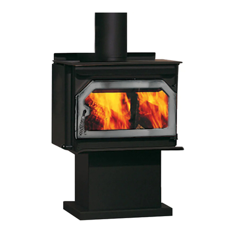
Encore®2040 Non-Catalytic Woodburning Stove
30006253
R = x T = x 0.5 = 0.59
1
k
1
0.84
1
0.29
The specied oor protector should be 1/2-
inch thick material with k-factor of 0.84. The proposed al-
ternate is 4” brick with an r-factor of 0.2 over 1/8” mineral
board with a k-factor of 0.29
Step a: Use formula above to convert specication to
R-value:
Step b: Calculate R of proposed system.
4” brick of r = 0.2, therefore:
Rbrick = 0.2 x 4 = 0.8
1/8” mineral board of k = 0.29, therefore
Rmineralboard = x 0.125 = 0.431
Rtotal = Rbrick + Rmineralboard = 0.8 + 0.431 = 1.231
Step c: Compare proposed system Rtotal of 1.231 to
specied R of 0.59. Since proposed system Rtotal is
greater than required, the system is acceptable.
Denitions
r = =
(ft2)(hr)(°F)
(Btu)(in)
1
k
(Btu)(ft)
(ft2)(hr)(°F)
K =
k = = K x 12
(Btu)(in)
(ft2)(hr)(°F)
R = (ft2)(hr)(°F)
Btu
Do not assume that your replace hearth is completely
noncombustible. Many replace hearths do not satisfy the
“completely noncombustible” requirement because the brick
or concrete in front of the replace opening is supported by
heavy wood framing. Because heat passes readily through
brick or concrete, it can easily pass through to the wood.
As a result, such replace hearths can be a re hazard and
are considered a combustible oor.
For all replace installations, follow the oor protection
guidelines described above, including the need for a bottom
shield. Keep in mind that many raised hearths will extend
less than the required clearance from the front of the heater.
In such cases, sufcient oor protection as described
above must be added in front of the hearth to satisfy the
minimum oor protector requirement from the front of the
stove: 16” (410 mm) in the United States and 18” (460 mm)
in Canada. Hearth rugs do not satisfy the requirement for
oor protection as they are not re proof.
Fireplace installations also have special clearance require-
ments to the side walls, side decorative trim and replace
mantel. Refer to the information on replace and mantel
trim shields in this section.
Both a stove and its chimney connector radiate heat in all
directions when operating, and nearby combustible materi-
als can overheat dangerously if they are too close to the
heat source. A safe installation requires that adequate
clearance be maintained between the hot stove and its
connector and nearby combustibles.
Clearance is the distance between either your stove or
chimney connector, and nearby walls, oors, the ceiling,
and any other xed combustible surface. The Encore has
specic clearance requirements that have been established
after careful research and testing. These clearance require-
ments must be strictly observed.
In addition, keep furnishings and other combustible ma-
terials away from the stove. In general, a distance of 48”
(1219 mm) must be maintained between the stove and
moveable combustible items such as drying clothes, furni-
ture, newspapers, rewood, etc. Keeping those clearance
areas empty assures that nearby surfaces and objects will
not overheat.
Clearance requirements are established to meet every
installation possibility, and they involve the combination
of these variables:
• When the stove pipe has no listed heat shield mounted
on it.
• When the wall has no heat shield mounted on it.
• When the wall has a heat shield mounted on it.
• When the wall and stove pipe have heat shields.
In general, the greatest clearance is required when you
place a stove and its connector near a wall with no heat
shield.
For example, when the Encore is installed using 6” con-
nector pipe parallel to the rear wall and no connector shield
is used, it must be at least 15” (381 mm) from the wall
behind it and at least 19” (483 mm) from walls on either
side. These dimensions are measured from the back of
the rear shroud and the side edge of the cast iron top to
the combustible wall.
If the Encore is installed in a corner and no shield is used,
the corners of the stove top must be at least 18Z\x” (470
mm) from nearby walls.
Clearances may be reduced only by means approved by
the regulatory authority, and in accordance with the clear-
ances listed in this manual. Refer to Page 12 for approved
clearance reduction specications.
