5
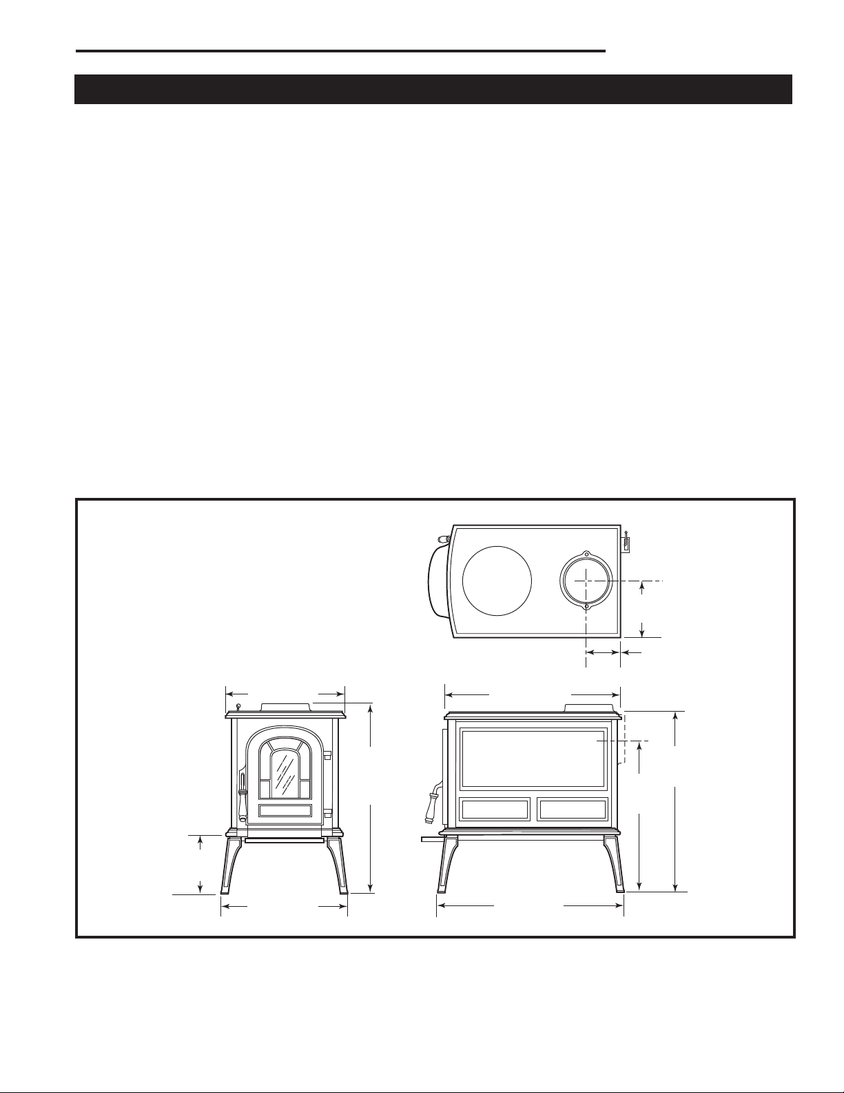
Aspen®Woodburning Stove
30003844
These should be an internal diameter of 150 mm (6”)
and be of the twin wall insulated construction that has
been approved for solid fuel use (e.g. Rite Vent ICS of
ICID Lite Chimney Systems). Diameters over 00 mm
(8”) are not recommended due to the large cross-sec-
tion causing excessive cooling of the ue gases.
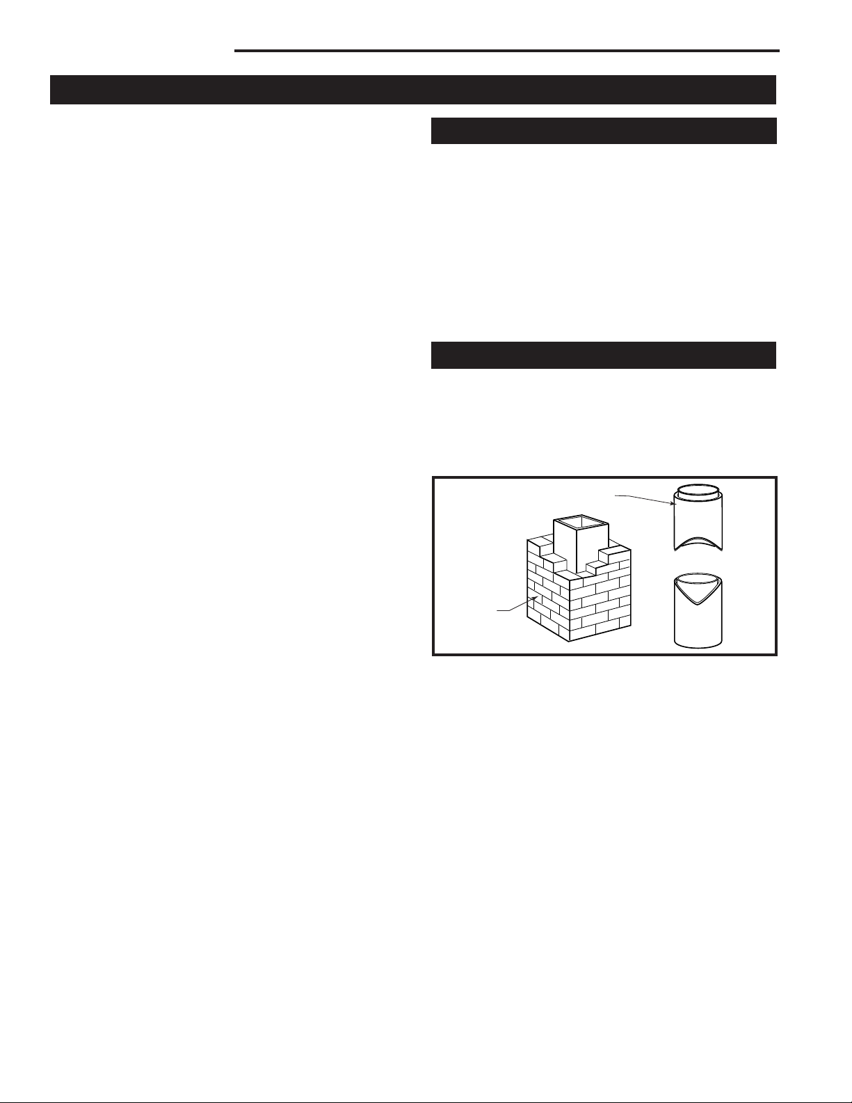
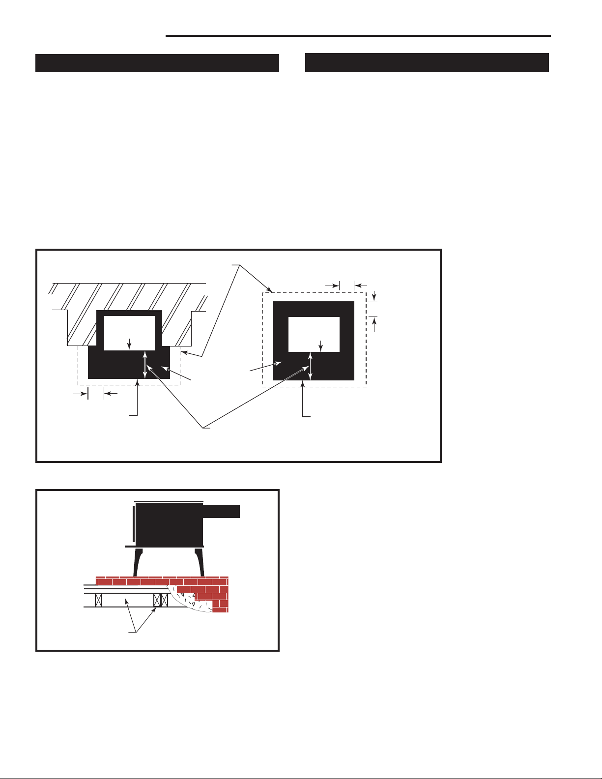
This stove is approved for venting into a masonry
chimney with a nominal ue size of 03 x 03 mm (8” x
8”), and into a round ue size of 03 mm (8”) or 15 mm
(6”).
It may be vented into larger chimneys as well. However,
chimneys with liners larger than 03 x 305 mm (8” x 1”)
may experience rapid cooling of smoke and reduction
in draft, especially if they are located outside the home.
Such large chimneys may need to be insulated or have
the ue relined for proper stove performance.
Ask your dealer about components available for con-
necting the stove to a steel chimney liner.
A chimney connector is the double-wall or single-wall
pipe that connects the stove to the chimney. The chim-
ney itself is a masonry or prefabricated structure that
encloses the ue. Chimney connectors are used only
to make the connection from the stove to the chimney.
They are for interior use only.
Connector pipes should meet the requirements of the
building regulations. This can be achieved by the use
connecting uepipes included in the following catego-
ries:
a) Vitreous enamelled steel pipe complying with BS
6999: 1989 (1996);
b) Pipes made from stainless steel as descirbed in BS
EN 1008-1:1995 grades 1.4401, 1.4404, 1.443 or
1.4436 with ue wall thickness of at least 1 mm;
c) Mild steel uepipes complying with BS 1449: Part 1:
1991, with a ue wall thickness of at least 3 mm;
d) Cast iron uepipes complying with BS 41: 1973
(1998).
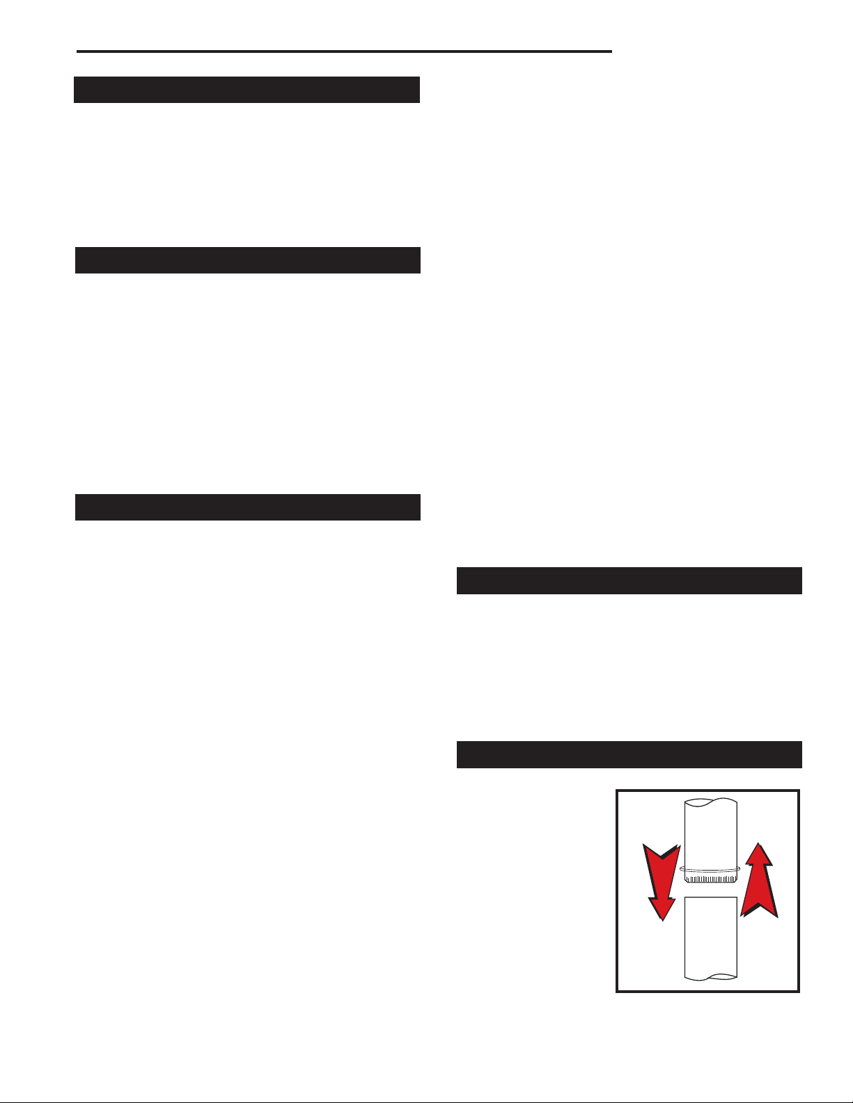
Flue Pipes with a spigot and socket joint should be
tted with the socket facing upwards, to contain con-
densates and moisture within the ue. Joints should be
made gas tight using proprietary jointing accessories,
or, where appropriate, by packing joint with noncombus-
tible rope and re cement.
Double-wall connectors must be tested and listed for
use with solid-fuel burning appliances. Single-wall con-
nectors should be made of 4 gauge or heavier steel,
and should be 15 mm (6”) in diameter. Do not use
galvanized chimney connector; it cannot withstand the
high temperatures that can be reached by smoke and
exhaust gases, and may release toxic fumes under high
heat.
If possible, do not pass the chimney connector through
a combustible wall or ceiling. If passage through a
combustible wall is unavoidable, refer to the recommen-
dations in the section following on Wall Pass-throughs.
Do not pass the connector through an attic, a closet or
any similar concealed space. The whole chimney con-
nector should be exposed and accessible for inspection
and cleaning.
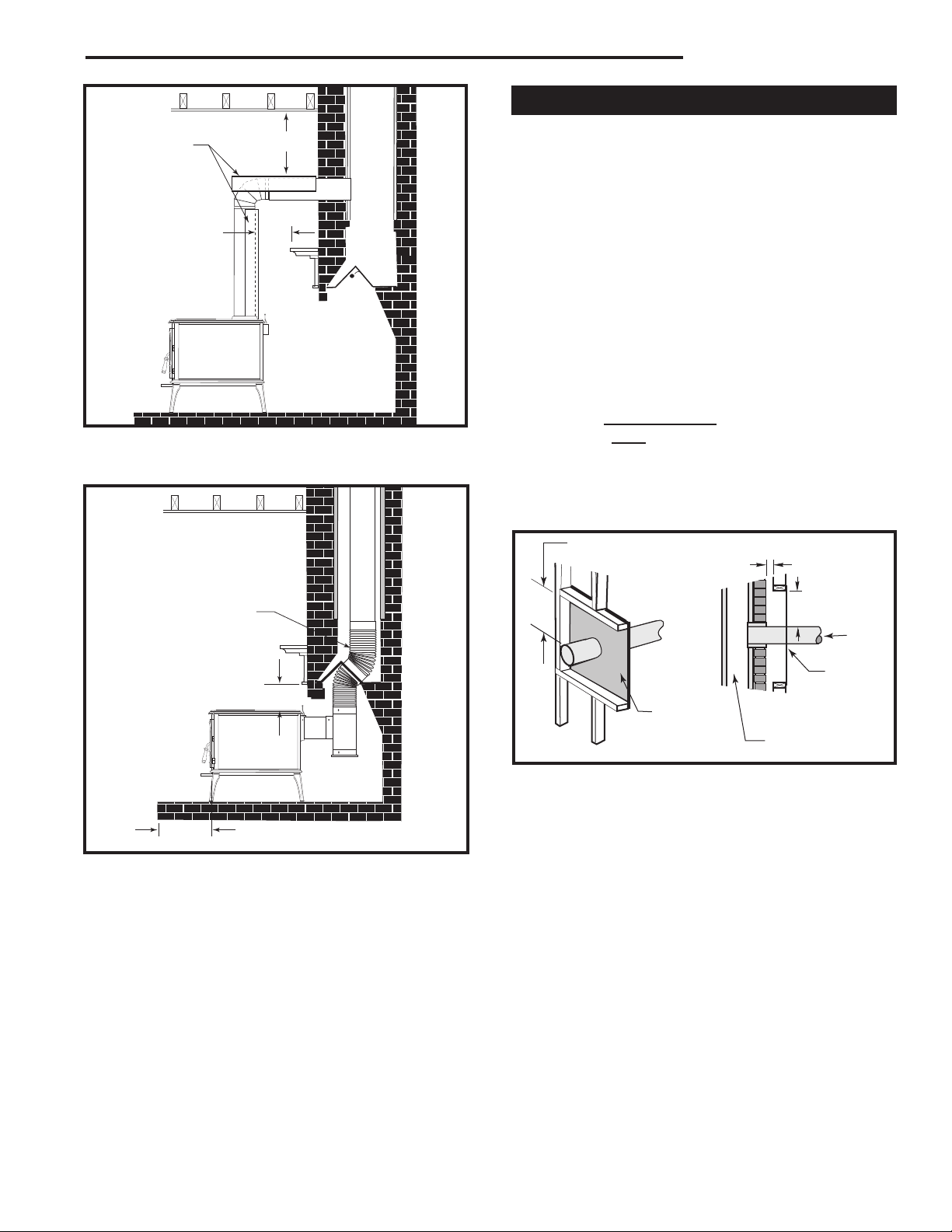
Install the single wall chimney connector not less than
457 mm (18”) from the ceiling. Keep it as short and
direct as possible, with no more than two 90 degree
turns. If possible, use 45° elbows. Slope horizontal runs
of connectors upward 0 mm per meter (1/4” per foot)
going from the stove toward the chimney. The recom-
mended maximum length of a horizontal run is 914 mm
(36”), and the total length of chimney connector should
be no longer than .5 m (8’).
In cathedral ceiling installations, extend the prefabricat-
ed chimney downward to within .5 m (8”) of the stove.
Follow the instructions for assembling and installing
double-wall connectors provided by the manufacturer
of the double-wall chimney. To ease assembly and help
assure safety, use chimney components manufactured
by a single source.
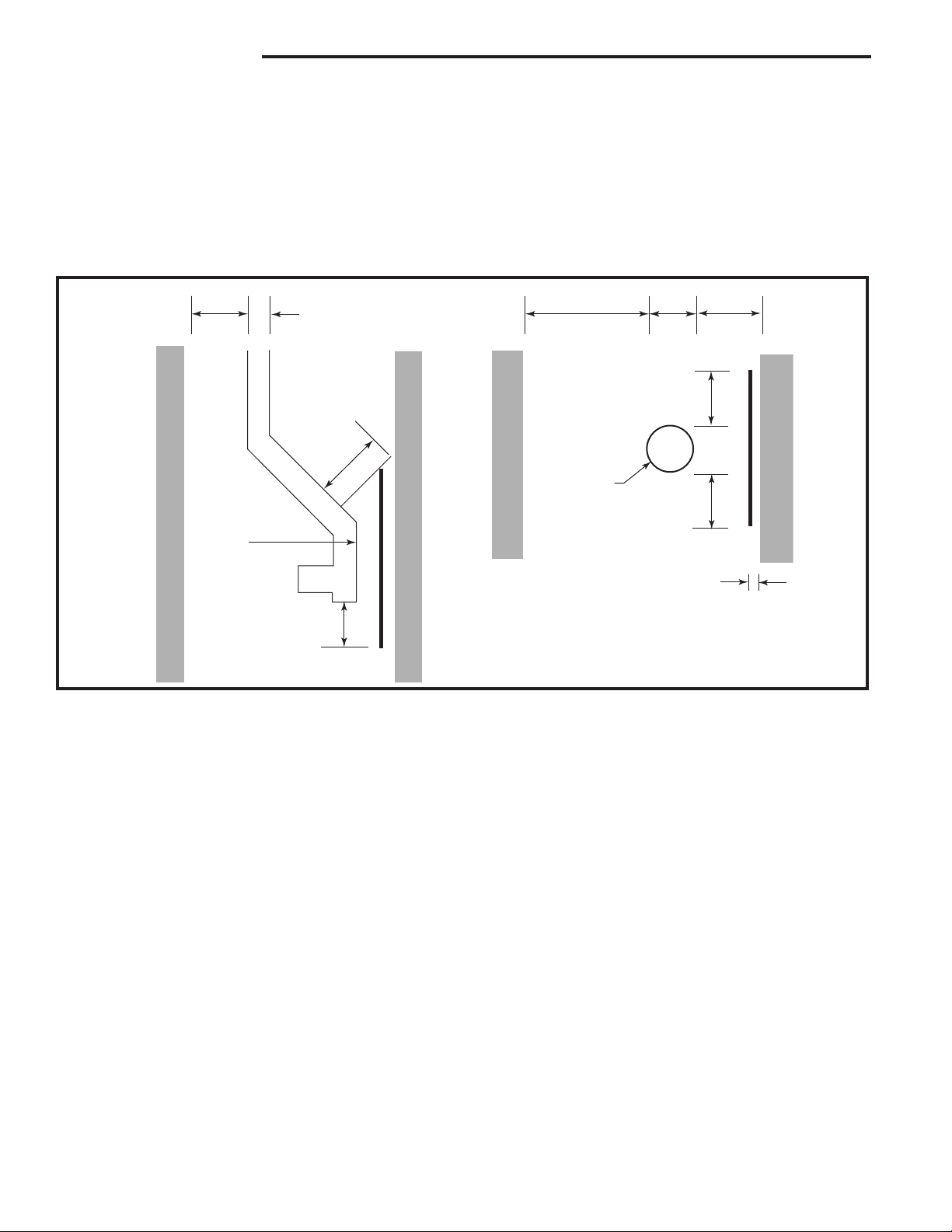
• Beginning at the ue collar of the stove, assemble
the chimney con-
nector. Insert the
rst crimped end
into the stove’s ue
collar, and keep
each crimped end
pointing toward the
stove. Using the
holes in the ue
collar as guides,
drill 1/8” (3 mm)
holes in the bottom
of the rst section
Toward
stove
Chimney connector.
ST242
Chimney connector
12/13/99 djt
Flue gas
direction