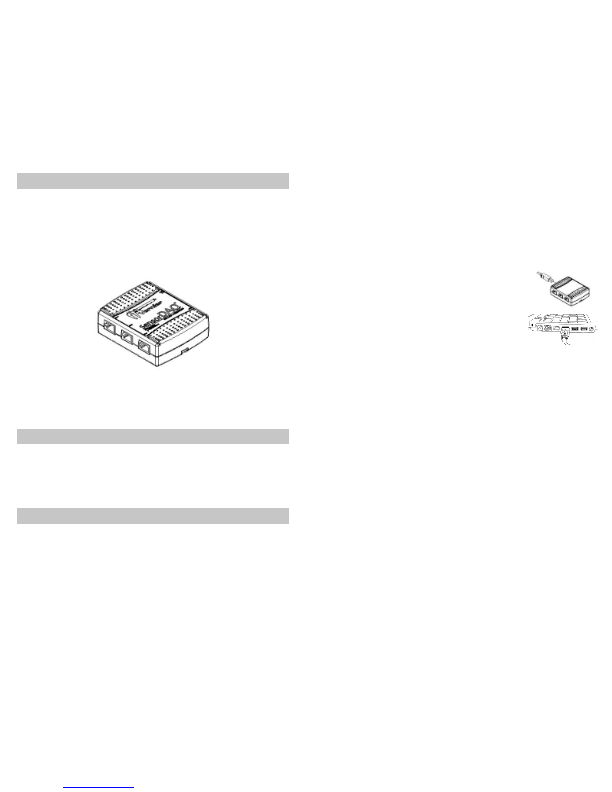
SensorDAQ User's Manual
9
Analog Input Wiring
In the differential input setting, connect the the positive lead of the source to
the AI(0) terminal, and the negative lead to the AI(1) terminal. The differential
input mode allows the SensorDAQ to measure a voltage difference on these
terminals up to +20V or –20V in the ±20V range; however, the maximum
voltage on any one terminal cannot exceed ±10 V with respect to GND. In the
referenced single-ended input mode setting, connect the positive lead of the
source to either AI channel terminal, AI(0) or AI(1), and the ground or
negative lead to the GND terminal.
Analog Output Wiring
The SensorDAQ has one AO channel that can generate an output from 0–5V.
The AO has an output current drive value of 5 mA. The maximum update
rate of the channel is 150 Hz, software timed. To connect loads to the
SensorDAQ, connect the positive lead of the load to the A0 terminal, and
connect the ground lead of the load to a GND terminal.
Digital I/O
In addition to supporting Vernier digital sensors, the SensorDAQ has four
digital lines, P0.<0..3>, which comprise the DIO port. GND is the ground-
reference signal for the DIO port. The default configuration of the
SensorDAQ DIO ports is open collector, allowing 5 V operation, with an
onboard 4.7 kΩpull-up resistor. An external, user-provided, pull-up resistor
can be added to increase the source current drive up to 8.5 mA limit per line.
Counter/Timer
SensorDAQ has a counter/timer that can be configured for pulse output,
timing input, event counting, or as a digital trigger.
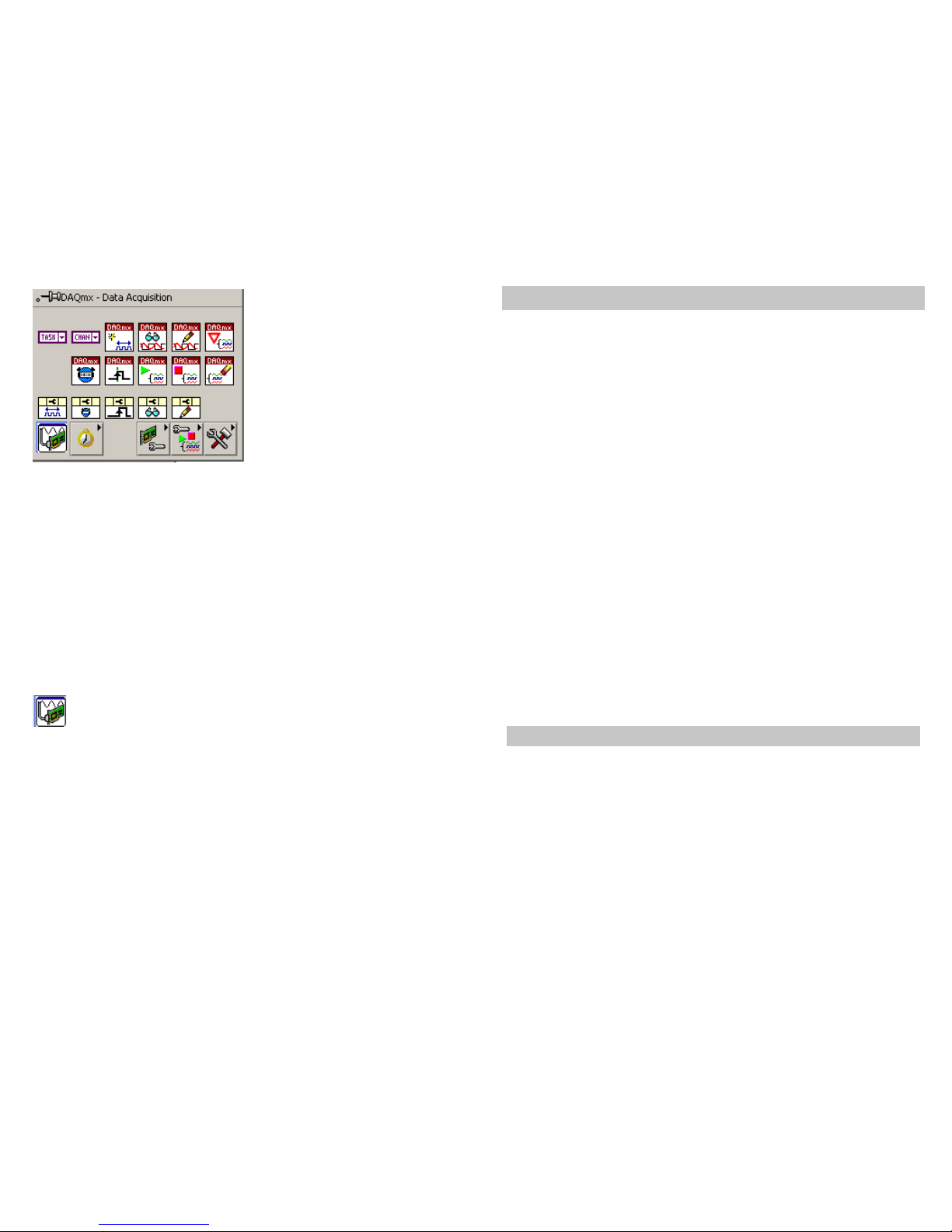
SensorDAQ Example VIs
The best way to get started with SensorDAQ is to open and run examples.
You can use the examples without modification for data logging with
analysis, for control, to perform output, to troubleshoot your hardware, and
as starting points for your own custom program.
The SensorDAQ examples are located in the LabVIEW\examples\Vernier
directory. An easy way to find the examples is to launch the LabVIEW
Example finder and open the Toolkits and Modules folder. The Example
Finder is launched from the Getting Started Window or from the Help » Find
Examples menu.
The examples are stored in descriptive folders. Locate the folder that best
SensorDAQ User's Manual
10
matches your sensor or how you plan to use the hardware. For best results,
explore all of the example folders and open a sampling of examples. Inside
the folders you may find examples labeled Starter. Open these examples first.
They are designed as a starting point for testing the hardware and learning
the LabVIEW code. There may also be subfolders that are labeled Advanced
Low Level. In general, these examples will only be useful if you require a
higher level of flexibility for communicating with the SensorDAQ.
The folders are explained below:
Digital Control Unit (DCU)
The Vernier DCU connects to the DIG Channel and provides output lines
that can control small electric devices. This is a great device for classroom
projects or discussion of sensor control. In this folder you will find examples
showing how to control the output lines, how to control lines based on sensor
readings going above or below threshold values, and how to control servo
and stepper motors connected to the DCU.
Feedback and Control
The SensorDAQ screw terminal provides digital input and output, analog
input, analog output and pulse output. The examples in this folder provide
examples of feedback and control using the screw terminal channels.
Log and Analyze Data
These are examples that are great for running science and engineering-type
experiments in the classroom. In this folder you will find examples with the
features required for collecting data and performing some type of analysis on
the data including; linear fit, curve fit, integral, statistics, tangent, and more.
In addition you will find examples for creating XY graphs, performing
events with entry, saving data to file, building tables, zeroing a sensor
reading, changing sensor units and more.
Inside this folder is a LabVIEW example VI called “SensorDAQ Logger.vi”.
This is an advanced example where Channels 1-3 can be used to collect data
with Vernier analog sensors, and the screw terminal inputs AI0 and AI1 can
be used to collect data with custom analog sensors. These five analog inputs
can be configured, and the calibration coefficients modified. Clicking on the
Data Collection button configures the data-collection rate, length of the
experiment, as well as any triggering. Once data have been collected, there
are some analysis features that can be used. If you would like to analyze a
small portion of the data, simply click and drag your mouse to highlight the