BEFORE INSTALLING THIS LIFT:
Verify that this product and its installation does not violate
local building codes. Youcan find out this information
from a local building inspector, architect, structural
engineer, or your buildingcontractor.
Find out if there are any code restrictions on what types
of things you can store in your attic.
Getprofessional adviceand estimates onframing,
decking and assembly if you are not qualified or
physically able to do these tasks. You can find building
contractors, remodeling contractors, architects,
engineers and inspectors in the Yellow Pages.
Youareresponsiblefordeterminingthesuitabilityofthis
product for your individual purposes, as well as installing
itin a waythat meetslocal building andsafetycodes.
Two persons are required to
perform certain tasks in this guide for safer and
easier installation. Performing these tasks alone is
not recommended.
Versa Lift
INSTALLATION OVERVIEW:
1.
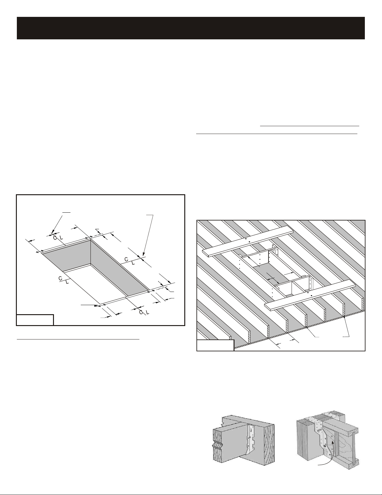
FRAME THE OPENING:
The first step to installing your new Versa Lift is preparing
an opening in the ceiling wheretheliftwill belocated.
Tools/Materials Required: Saws, Drill-Driver, Hammer,
Nails or Screws, Framing Square, Tape Measure, Header
& Joist Lumber to match your existing joists.
Skill Level: Professional - Only attempt this part of the
installationyourselfifyouareskilledinconstruction-type
framing.Ifyouarenot,youshouldhireaVersaLiftdealer
or a building/remodeling contractor to do this job for you.
Before cutting any ceiling joist, consult a contractor or
structural engineer to determine the best location to
install your lift. Also, if your attic is not already decked,
get some advice on the best areas to add decking in your
attic for storage.
2.
FLOORING AN ATTIC SPACE:
If your attic is not already floored in the area where your
Versa Lift will be installed, then flooring material such as
plywoodmust be addedontopof the ceiling joiststo
makea floor thatyoucan walkon andstoreitemson.
Tools/Materials Required: Skill Saw, Hammer and Nails
or Screws and Power Driver, Framing Square, Tape
Measure, and Decking Material.
Skill Level: Handyman - If you have skill with general
carpentry tools (sawing, measuring, nailing or screwing)
and the physical strength to move large pieces of wood,
then you can do this part yourself with a helper.
(
You can
get 4 x 4-ft. or 2 x 8-ft. pre-cut plywood at most lumber
stores. It is much easier to handle than 4 x 8-ft sheets.)
3.
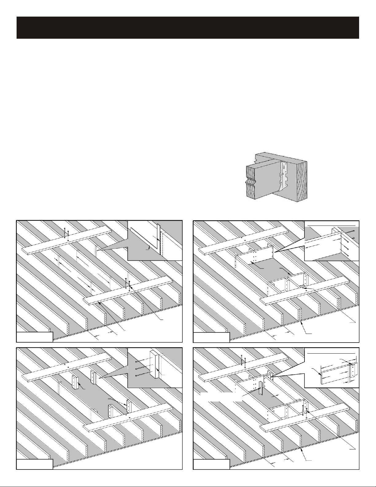
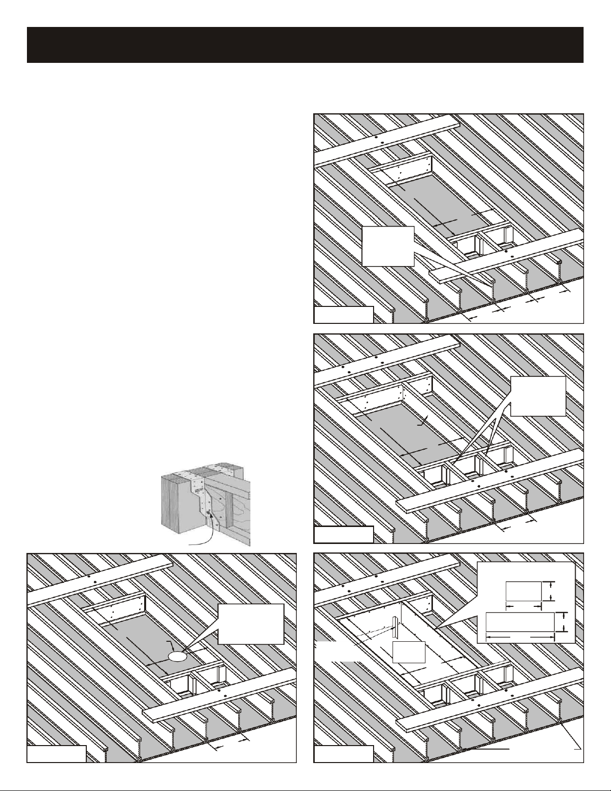
ASSEMBLE AND INSTALL THE LIFT:
The Versa Lift comes partially assembled. The cartons
contain all of the parts and fastening hardware, along
with detailed instructions in this guide for assembly.
Tools/Materials Required: A Power Drill-Driver, 5/32”
Drill Bit, Phillips Driver Bit, Socket Driver Bit, Tape
Measure, Square, Level, Phillips Screwdriver, 3/8” & 7/16”
Wrenches, and 3/8” & 7/16” Sockets and Ratchet.
Skill Level: Handyman - If you have the skill for general
repair and maintenance using hand tools and can read
and follow instructions, then you can do this part yourself
with a helper.
VERSA LIFT SPECIFICATIONS:
General Specifications (All Models 32)
Dimensions 34W x 69L x 60H
Vertical Attic Space Req’d. 60” Min.
Max. Joist Height 18”
Lift Opening Size 30.5 x 58.5”
Motor 0.6 hp
Voltage
120 VAC
Power 5 amps
Lift Capacity Max.
250 lbs.
Lifting Speed
8 in/sec
DutyCycle(minutes) 2 on / 4 off
Lifting Cables (2) .093 (7x19)
Shipping Wt. (approx) 220 lbs.
Model Floor-to Floor
32......................................................................8-11 ft.
32H..................................................................11-14 ft.
32HX...............................................................14-17 ft.
32HXX.............................................................17-20 ft.
Control Options
Handheld Remote...............(keylock and 15-ft cord)
Wall Mounted Switch Set....(downstairs has keylock)
Wireless Remote........(with powerful Radio Receiver)