Vertex Standard VX-P820 Series User manual

VX-P820 SerieS
OPerating Manual
A321
B654
C987
D0
A B C D
16-Key VerSiOn 4-Key VerSiOn nOn-lCD VerSiOn Vertex Standard LMR, Inc.

COntentS
Important Note ......................................................... 2
Intrinsic Safety (IS) Information ............................ 3
Warning! FCC RF Exposure Requirements .......... 4
Controls & Connectors (16-Key Version) .............. 6
Controls & Connectors (4-Key Version) ................ 7
Controls & Connectors (Non-LCD Version) ......... 8
LCD Icons & Indicators (16- & 4-Key Versions) .. 9
Battery Terminals ................................................... 10
Before You Begin .....................................................11
Battery Pack Installation and Removal ..............11
Battery Charging (VAC-UNI: CD-58/PA-55) ... 12
Battery Charging (VAC-921: CD-53/PA-42)..... 14
Low Battery Indication ...................................... 15
Operation ................................................................ 16
Preliminary Steps ............................................... 16
Operation Quick Start ........................................ 16
Automatic Time-Out Timer ............................... 18
Advanced Operation .............................................. 20
Programmable Key Functions .......................... 20
Description of Operating Functions ................. 22
ARTS™ (Auto Range Transpond System) .......... 30
DTMF Paging System ............................................ 30
MDC1200® Encoding ............................................. 30
RSSI Beep ............................................................... 31
Caller ID Display .................................................... 31
LOCK ...................................................................... 31
User Set Mode......................................................... 32
Optional Accessories .............................................. 34
Warranty Policy ..................................................... 36

1
VX-P820 SerieS OPerating Manual
Congratulations!
You now have at your ngertips a valuable communications tool-a Vertex Standard two-way radio! Rugged, reli-
able and easy to use, your Vertex Standard radio will keep you in constant touch with your colleagues for years to
come, with negligible maintenance down-time. Please take a few minutes to read this manual carefully. The in-
formation presented here will allow you to derive maximum performance from your radio, in case questions arise
later on.
We’re glad you joined the Vertex Standard team. Call on us anytime, because communications is our business. Let
us help you get your message across.

2
VX-P820 SerieS OPerating Manual
important note
r There are no owner-serviceable parts inside the radio. All service jobs must be referred to an authorized Vertex
Standard Service Representative. Consult your Authorized Vertex Standard Dealer for installation of optional
accessories.
r In order to maintain the specied water integrity performance, periodic maintenance is recommended.
r Should the radio sustain a severe shock (e.g. if it is dropped), the water integrity may be compromised, requir-
ing service. Should this occur, contact your Authorized Vertex Standard Dealer.
Important Notice for North American Users Regarding 406 MHz Guard Band
The U.S. Coast Guard and National Oceanographic and Atmospheric Administration have requested the
cooperation of the U.S. Federal Communications Commission in preserving the integrity of the protected
frequency range 406.0 to 406.1 MHz, which is reserved for use by distress beacons. Do not attempt to pro-
gram this apparatus, under any circumstances, for operation in the frequency range 406.0 - 406.1 MHz if
the apparatus is to be used in or near North America.
Warning - Frequency band 406 - 406.1 MHz is reserved for use ONLY as a distress beacon by the US
Coast Guard and NOAA. Under no circumstance should this frequency band be part of the pre pro-
grammed operating frequencies of this radio.

3
VX-P820 SerieS OPerating Manual
intrinsiC safety (is) information
IS versions of the VX-P820, equipped with any of the following optional units, meets the requirements of ANSI/
UL 913 5th Edition for Class I, II, III, Division 1 Groups C, D, E, F, G, T3C for hazardous locations.
Battery Packs: FNB-V129LIIS-UNI
Speaker Microphone: MH-50D7A, MH-66A7A, MH-66B7A
r Never charge the battery in the hazard areas.
r Never install/removal the battery in the hazard areas.
r Never install/remove the optional unit (includes the Speaker Microphone) in the hazard areas.
r The VX-P820 shall not be directly installed or used in any process where its enclosure might be electrostati-
cally charged by the rapid ow of a non-conductive media.
r Ensure that there is no external damage to the radio, antenna or battery before entering the potentially explo-
sive atmospheres, as it might compromise the safety of the unit. eg an antenna with a damaged end or insula-
tion must be replaced before use in any potentially explosive atmospheres.
r Substitution of components may impair intrinsic safety. Installation of FNB-V129LIIS-UNI does NOT convert
normal radio into IS version.
r
To acquire the IS version of the VX-P820, you much select the Intrinsically Safe battery option at the time of
purchase.

4
VX-P820 SerieS OPerating Manual
Warning! fCC rf exposure requirements
This Radio has been tested and complies with the Federal Communications Commission (FCC) RF exposure lim-
its for Occupational Use/Controlled exposure environment. In addition, it complies with the following Standards
and Guidelines:
r FCC 96-326, Guidelines for Evaluating the Environmental Effects of Radio-Frequency Radiation.
r FCC OET Bulletin 65 Edition 97-01 (1997) Supplement C, Evaluating Compliance with FCC Guidelines for
Human Exposure to Radio Frequency Electromagnetic Fields.
r ANSI/IEEE C95.1-1992, IEEE Standard for Safety Levels with Respect to Human Exposure to Radio Fre-
quency Electromagnetic Fields, 3 kHz to 300 GHz.
r ANSI/IEEE C95.3-1992, IEEE Recommended Practice for the Measurement of Potentially Hazardous Electro-
magnetic Fields - RF and Microwave.
WARNING:
This radio generates RF electromagnetic energy during transmit mode. This radio is designed for and clas-
sied as Occupational Use Only, meaning it must be used only during the course of employment by indi-
viduals aware of the hazards, and the ways to minimize such hazards. This radio is not intended for use by
the General Population in an uncontrolled environment.
CAUTION:
To ensure that your expose to RF electromagnetic energy is within the FCC allowable limits for occupa-
tional use, always adhere to the following guidelines:
¦ This radio is NOT approved for use by the general population in an uncontrolled exposure environment.
This radio is restricted to occupational use, work related operations only where the radio operator must
have the knowledge to control his or her RF exposure conditions.
¦ When transmitting, hold the radio in a vertical position with its microphone 2 inches (5 cm) away from
your mouth and keep the antenna at least 2 inches (5 cm) away from your head and body.

5
VX-P820 SerieS OPerating Manual
Warning! fCC rf exposure requirements
¦ The radio must be used with a maximum operating duty cycle not exceeding 50%, in typical Push-to-
Talk congurations.
DO NOT transmit for more than 50% of total radio use time (50% duty cycle). Transmitting more than
50% of the time can cause FCC RF exposure compliance requirements to be exceeded.
The radio is transmitting when the red LED on the top of the radio is illuminated. You can cause the
radio to transmit by pressing the P-T-T button.
¦ SAR compliance for body-worn use was only demonstrated for the specific belt-clip Part Number
(CLIP-820). Other body-worn accessories or congurations may NOT comply with the FCC RF expo-
sure requirements and should be avoided.
¦ DO NOT transmit when the radio is used in Body Worn configuration with the following accessory:
belt-clip.
It must be used ONLY for (1) there is 1.5 inches (4 cm) distance from the body during transmitting,
(2) monitoring purposes, using the speaker only and (3) for carrying purposes.
¦ Always use Vertex Standard authorized accessories.
¦ The information listed above provides the user with the information needed to make him or her aware
of RF exposure, and what to do to assure that this radio operates with the FCC RF exposure limits of
this radio.
¦ Electromagnetic Interference/Compatibility
During transmissions, this radio generates RF energy that can possibly cause interference with other de-
vices or systems. To avoid such interference, turn off the radio in areas where signs are posted to do so.
Do not operate the transmitter in areas that are sensitive to electromagnetic radiation such as hospitals,
health care facilities, aircraft, and blasting sites.

6
VX-P820 SerieS OPerating Manual
Control & ConneCtors (16-Key Version)
VOL/PWR Knob LED Indicator
Steady Red:
Transmitting in progress
Blinking Green:
Busy Channel
Steady Green:
Tone Squelch in defeated condition
Dealer Programmed Colorø
Emergency, 5-Tone Decoded, or
2-Tone Decoded
CH (Channel) Selector
Antenna Jack
TOP SEL Key
Speaker
Microphone
PTT Switch
MONITOR Button
LAMP Button
MIC/SP Jack
(External MIC/SP)
LCD (Liquid Crystal Display)Battery Pack Latch 16-Button DTMF Keypad
ø one of “Flashing in white”,
“Continuation changes
in sequential colors”, or
“Toggling the two colors”.
A321
B654
C987
D0

7
VX-P820 SerieS OPerating Manual
Control & ConneCtors (4-Key Version)
VOL/PWR Knob LED Indicator
Steady Red:
Transmitting in progress
Blinking Green:
Busy Channel
Steady Green:
Tone Squelch in defeated condition
Dealer Programmed Colorø
Emergency, 5-Tone Decoded, or
2-Tone Decoded
CH (Channel) Selector
Antenna Jack
TOP SEL Key
Speaker
Microphone
PTT Switch
MONITOR Button
LAMP Button
MIC/SP Jack
(External MIC/SP)
LCD (Liquid Crystal Display)Battery Pack Latch 4-Button Programmable Key
ø one of “Flashing in white”,
“Continuation changes
in sequential colors”, or
“Toggling the two colors”.
A B C D

8
VX-P820 SerieS OPerating Manual
Control & ConneCtors (non-lCD Version)
VOL/PWR Knob LED Indicator
Steady Red:
Transmitting in progress
Blinking Green:
Busy Channel
Steady Green:
Tone Squelch in defeated condition
Dealer Programmed Colorø
Emergency, 5-Tone Decoded, or
2-Tone Decoded
CH (Channel) Selector
Antenna Jack
TOP SEL Key
Speaker
Microphone
PTT Switch
MONITOR Button
LAMP Button
MIC/SP Jack
(External MIC/SP)
Battery Pack Latch
ø one of “Flashing in white”,
“Continuation changes
in sequential colors”, or
“Toggling the two colors”.

9
VX-P820 SerieS OPerating Manual
lCD iCons & inDiCators (16-Key & 4-Key Versions)
“CALL” Indicator
: This channel on the “SCAN” List
: “Priority Scan” is activated
“Dual Watch” is activated
Option Switch (Key Function) is activated
Low Transmit Power Mode On
RSSI Indicator (four steps)
Encryption is activated
Receiver Monitor
“Talk-Around” is enabled
Battery Indicator
“Group Scan” is enabled
12 Character Alpha-numeric Display
SUB-LCD : Channel Group Number
: Priority Channel
: Home Channel
: ARTS™ “In Range”
: ARTS™ “Out of Range”

10
VX-P820 SerieS OPerating Manual
Battery terminals
VHF Model UHF Model
Maximum Input Voltage: 8.4 V DC 8.4 V DC
Maximum Input Current: 2.5 A 2.5 A
Maximum Input Power: 21 W 21 W
Maximum Internal Capacitance: 50.52 μF 51.32 μF
Maximum Internal Inductance: 5.51 μH 5.46 μH

11
VX-P820 SerieS OPerating Manual
Before you Begin
Battery Pack Installation and Removal
r To install the battery, hold the transceiver with
your left hand, so your palm is over the speaker
and your thumb is on the top of the belt clip.
Carefully mate the battery’s four insertion slots
with their corresponding alignment tabs on the
transceiver case, while tilting the Belt Clip out-
ward. Proper alignment occurs with the battery
pack offset about 1/2 inch (1.5 cm) from the top
edge of the battery compartment.
r Guide the pack on to the tabs with a slight inward
pressure, then slide the battery pack upward, until
it locks in place with a “Click”.
Insert the Battery Pack
Tilt the Belt Clip
r To remove the battery, turn the radio off and re-
move any protective cases. Slide the Battery Pack
Latch on the bottom of the radio toward the front
panel while sliding the battery down about 1/2
inch (1.5 cm). Then lift the battery out from the
radio while unfolding the Belt Clip.
Do not attempt to open any of the recharge-
able Lithium-Ion packs, as they could ex-
plode if accidentally short-circuited.
WARNING
The IS version of the VX-P820 is only intrin-
sically safe with the use of the FNB-V129LI-
IS-UNI Battery Pack. To acquire the IS ver-
sion of the VX-P820, you much select the
Intrinsically Safe battery option at the time of
purchase. Replacement FNB-V129LIIS-UNI
battery may also be purchased however to be
considered IS the radio must have originally
been purchased with the IS battery option.
¦ Do not reverse-connect the battery terminals.
¦ Do not parallel-connect the battery terminals.
¦ Do not charge batteries in hazardous loca-
tions.
¦ To reduce the risk of explosion, recharge
the batteries outside of hazardous locations.
12
VX-P820 SerieS OPerating Manual
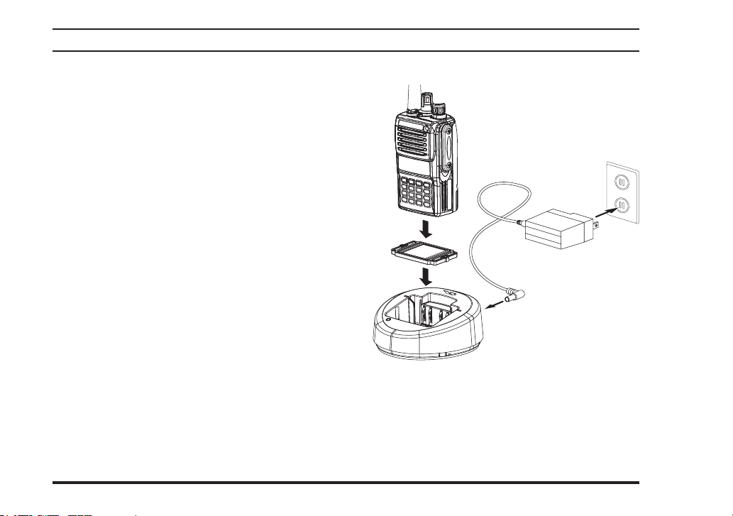
Battery Charging (VAC-UNI: CD-58/PA-55) for the FNB-V127LI-UNI/-V128LI-UNI/-V129LI-UNI/-V129LIIS-UNI
Before you Begin
r Install the Spacer Plate to the nest of the optional
CD-58 Desktop Charger, if the Battery Spacer is
not installed.
r Insert the DC plug from the optional PA-55 AC
Adapter into the DC jack on the rear panel of the
optional CD-58 Desktop Charger, and then con-
nect the PA-55 AC Adapter to the AC line outlet.
r Insert the battery pack into the CD-58 Desktop
Charger while aligning the slots of the battery
pack with the guides in the nest of the CD-58;
refer to the following illustration for details on
proper positioning of the battery pack. If charging
with the transceiver attached, turn the transceiver
off. The antenna jack should be at the left side
when viewing the charger from the front.
r If the battery pack is inserted correctly, the LED
indicator will glow red. A fully-discharged battery
pack will charge completely in 1.5 - 3.0 hours
(depending on the battery pack being charged).
r When charging is completed, the LED indicator
will change to green.
r Disconnect the battery pack from the CD-58
Desktop Charger and unplug the PA-55 AC
Adapter from the AC line outlet.
AC Line Outlet
Spacer Plate
PA-55
CD-58

13
VX-P820 SerieS OPerating Manual
1) The VAC-UNI (CD-58/PA-55) charges
only the Vertex Standard FNB-V127LI-UNI,
FNB-V128LI-UNI, FNB-V129LI-UNI and FNB-
V129LIIS-UNI Lithium-Ion Battery Pack.
2) If the IS version of the VX-P820 is being used in
a hazardous environment where Intrinsic Safety (IS)
is required you must use the FNB-V129LIIS-UNI
battery.
3) Use only the Vertex Standard PA-55 AC Adapter.
4) To reduce the risk of explosion, recharge the bat-
teries outside of hazardous locations.
5) Perform the battery charging where the ambient
temperature range +41 °F to +104 °F (+5 °C to +40
°C). Charge out of this range could cause damage to
the battery pack.
6) Battery Pack shall not be exposed to excessive
heat such as sunshine, re, or the like.
7) Risk of explosion if battery is replaced by an in-
correct type. Dispose of used batteries according to
the instructions.
8) For further details and cautions of the charging,
refer to the Operating Manual of the CD-58 Desktop
Charger.
Before you Begin

14
VX-P820 SerieS OPerating Manual
Align the slots of the battery pack
with the guides in the nest of the
CD-53 Desktop Rapid Charger.
Insert the DC plug from
the PA-42 AC Adapter
into the DC jack of the
CD-53 Desktop Rapid
Charger.
Battery Charging (VAC-921: CD-53/PA-42) for the FNB-V86LIA/-V87LIA/-V92LI
Before you Begin
r Insert the DC plug from the PA-42 AC Adapter
into the DC jack on the bottom side of the CD-53
Desktop Rapid Charger, then plug the PA-42 AC
Adapter into the AC line outlet.
r Insert the battery pack into the CD-53 Desktop
Rapid Charger while aligning the slots of the bat-
tery pack with the guides in the nest of the CD-
53; refer to the illustration at the right for details
on proper positioning of the pack. If charging
with the transceiver attached, turn the transceiver
off, and the antenna jack should be at the left side
when viewing the charger from the front.
r If the battery pack is inserted correctly, the LED
indicator will glow red. A fully-discharged pack
will be charged completely in 1.5 - 3.0 hours (de-
pending on the battery pack being charged).
r The LED indicator will blink red/green alternately
when charging is nearing completion.
r When charging is completed, the LED indicator
will change to green. Even if the charging is com-
pleted, the LED indicator will sometimes change
to red for trickle charging.
r Disconnect the pack from the CD-53 Desktop
Rapid Charger, and unplug the PA-42 AC Adapter
from the AC line outlet.

15
VX-P820 SerieS OPerating Manual
Before you Begin
1) The VAC-921 (CD-53/PA-42) charges
only the Vertex Standard FNB-V86LIA,
FNB-V87LIA, and FNB-V92LI Lithium-Ion Battery
Pack.
2) If the IS version of the VX-P820 is being used in
a hazardous environment where Intrinsic Safety (IS)
is required you must use the FNB-V129LIIS-UNI
battery with the VAC-UNI Desktop Rapid Charger.
3) Use only the Vertex Standard PA-42 AC Adapter.
4) To reduce the risk of explosion, recharge the bat-
teries outside of hazardous locations.
5) Perform the battery charging where the ambient
temperature range +41 °F to +104 °F (+5 °C to +40
°C). Charge out of this range could cause damage to
the battery pack.
6) Battery Pack shall not be exposed to excessive
heat such as sunshine, re, or the like.
7) Risk of explosion if battery is replaced by an in-
correct type. Dispose of used batteries according to
the instructions.
Low Battery Indication
As the battery discharges during use, the voltage
gradually becomes lower. When the battery voltage
becomes to low, substitute a freshly charged battery
and recharge the depleted pack. The LED indicator
on the top of the radio will blink red when the battery
voltage is low.
Caution
Danger of explosion if battery is replaced with
an incorrect battery. Replace only with the
same or equivalent type.
Note
The FBA-34 was designed as a backup bat-
tery pack, and it can be used to power the
transceiver if you are in an area that does not
require the use of an intrinsically safe radio.
16
VX-P820 SerieS OPerating Manual
operation
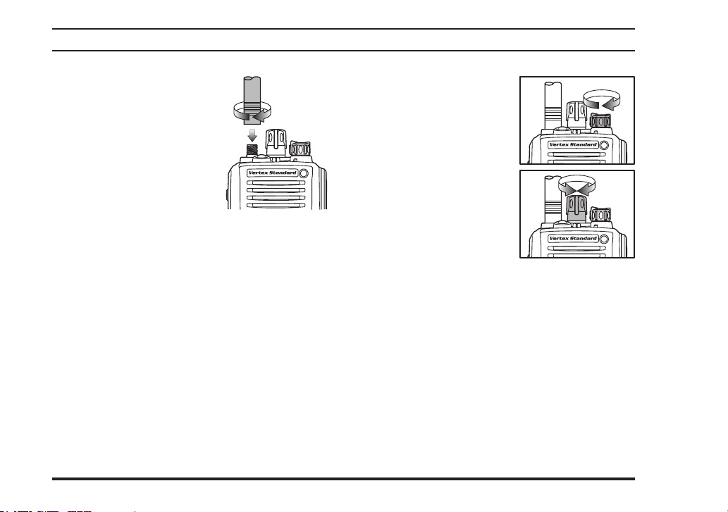
Preliminary Steps
r Install a charged battery
pack onto the transceiver, as
described previously.
r Screw the supplied antenna
onto the Antenna jack.
Never attempt to operate
this transceiver without an
antenna connected.
r If you have a Speaker/Mi-
crophone, we recommend that it not be connected
until you are familiar with the basic operation of
the VX-P820.
Operation Quick Start
r Turn the top panel’s
VOL/PWR knob clock-
wise to turn the radio on.
r Turn the top panel’s CH
selector knob to choose
the desired operating
channel. On the 16-key
and 4-key versions, a
channel name will appear
on the LCD.
r If you want to select the operating channel from a
different Memory Channel Group, press the Pro-
grammable key (assigned to the Memory Group
Up or Down function) to select the Memory
Channel Group you want before selecting the op-
erating channel. A Group name will appear on the
LCD whenever the Programmable key is pressed.
Note: Some models are programmed so that the
operating channels are selected by the Program-
mable key and the memory channel group is
selected by the CH selector knob. For further de-
tails, contact your Vertex Standard dealer.

17
VX-P820 SerieS OPerating Manual
r Rotate the VOL/PWR
knob to set the volume
level. If no signal is pres-
ent, press and hold in the
MONITOR button (under
the PTT switch) more than
2 seconds; background
noise will now be heard,
and you may use this to
set the VOL/PWR knob
for the desired audio
level. Press and hold the
MONITOR button more than 2 seconds (or press
the MONITOR button twice) to quiet the noise
and resume normal (quiet) monitoring.
r To transmit, monitor the
channel and make sure it
is clear.
Press and hold the PTT
switch. Speak into the
microphone area of the
front panel (at the lower right corner of the speak-
er grille) in a normal voice level. To return to the
Receive mode, release the PTT switch.
operation
r Press the (Orange) TOP
SEL key to activate one
of the pre programmed
functions which may
have been enabled at the
time of programming by
the dealer. See the next section for details regard-
ing the available features.
r If a Speaker/Microphone is available, remove
the plastic cap and its two mounting screws
from the right side of the trans-
ceiver, then align the connector
of the Speaker/Microphone on
the transceiver body; secure the
connector pin using the screws
supplied with the Speaker/
Microphone. Hold the speaker
grille up next to your ear while
receiving. To transmit, press the PTT switch on
the Speaker/Microphone, just as you would on the
main transceiver’s body, and speak into the micro-
phone on a normal voice level.
Note 1): Save the original plastic cap and its
mounting screws. They should be reinstalled
when not using the Speaker/Microphone.
2) When you press the PTT switch on the Speak-
er/Microphone, it disables the internal micro-

18
VX-P820 SerieS OPerating Manual
phone, and vice versa.
Do not remove/install the Speaker/Micro-
phone in a hazardous location.
r If the Busy Channel Lockout feature has been pro-
grammed on a channel, the radio will not trans-
mit when a carrier is present. Instead, the radio
will generate short beep three times and indicate
“ÝCH BusyÝ” on the display (16-key and
4-key versions). Release the PTT switch and wait
for the channel to be clear of activity.
r If CTCSS or Digital Coded Squelch (DCS) Lock-
out has been programmed on a channel, the radio
can transmit only when there is no carrier being
received or when the carrier being received in-
cludes the correct CTCSS tone or DCS code.
Automatic Time-Out Timer
If the selected channel has been programmed for au-
tomatic time-out, you must limit the length of each
transmission. While transmitting, a beep will sound
10 seconds before time-out. Another beep will sound
just before the deadline; the “TX” indicator will dis-
appear and transmission will cease soon thereafter. To
resume transmitting, you must release the PTT switch
and wait for the “Penalty timer” to expire.
operation
Other manuals for VX-P820 Series
2
Table of contents
Popular Conference System manuals by other brands


Sony
Sony Ipela PCS-XG80 operating instructions

Unify
Unify OpenScape Business V2 How-to

Flexitron
Flexitron webdyn MTX-StarWater Software user's guide

Studer
Studer Xcom-GSM user manual

Shenzhen PUAS Industrial Co., Ltd
Shenzhen PUAS Industrial Co., Ltd PUS-OHD200S SERIES user manual

Crestron
Crestron CCS-UC-1-X quick start