CMX UHF-300 User manual

UHF-300
WIRELESS CONFERENCE SYSTEM
Version: REV1.0 (201 )
O
PERATION
MANUAL

UHF-300 Wireless Conference Syste
1
CONTENTS----------------------------------------------------------------------------------2
1. System Configuration and description-----------------------------------------------2
1.1 System features-----------------------------------------------------------------------2
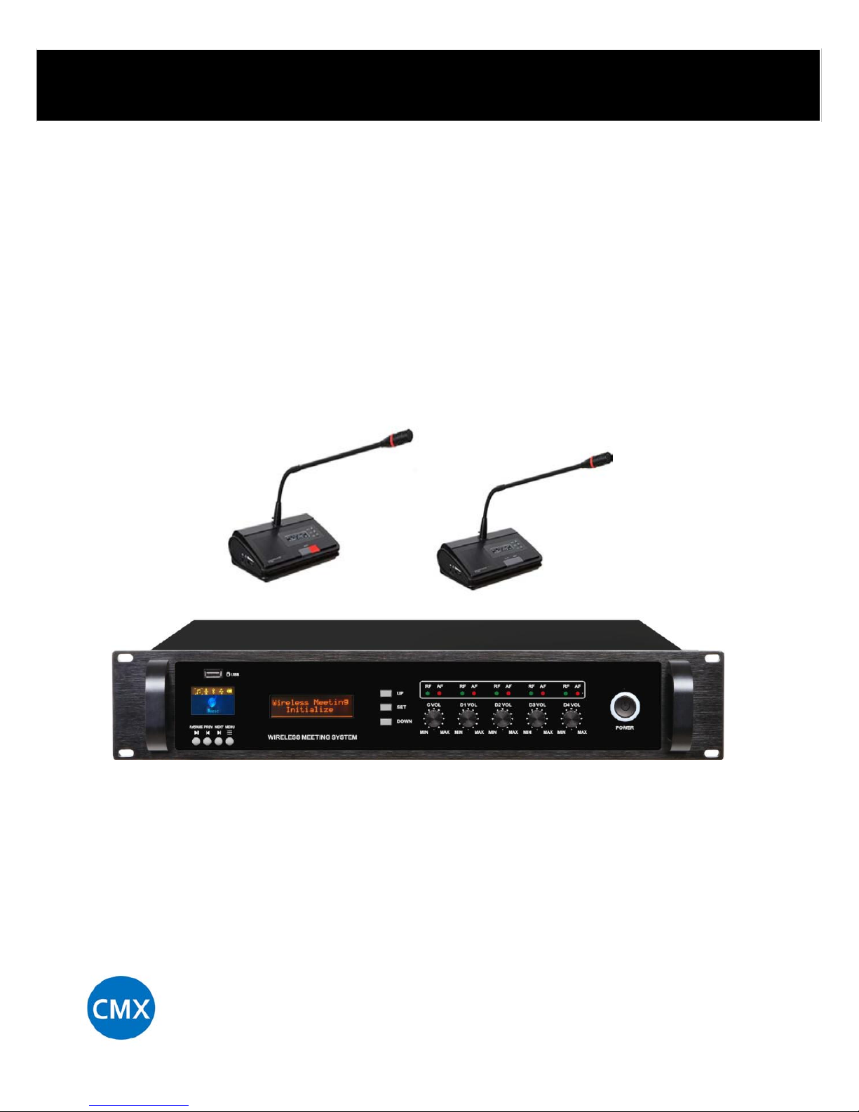
1.2 Wireless meeting system receiver unit ---------------------------------------------2
1.2.1 Picture of the actual object -----------------------------------------------------------2
1.2.2 Features of ireless meeting system receiver unit ----------------------------------3
1.2.3 Schematic diagram of ireless meeting system receiver unit -----------------------3
1.2.4 Parameter of ireless meeting system receiver unit---------------------------------4
1.3 Wireless meeting system microphone unit ------------------------------------------4
1.3.1 Picture of the actual object -----------------------------------------------------------5
1.3.2 Features of ireless delegate microphone unit --------------------------------------5
1.3.3 Features of ireless chairman microphone unit -----------------------------------5
1.3.4 Schematic diagram of ireless microphone -----------------------------------------5
1.3.5 Parameter of Parameter of ireless microphone-------- ----------------------------6
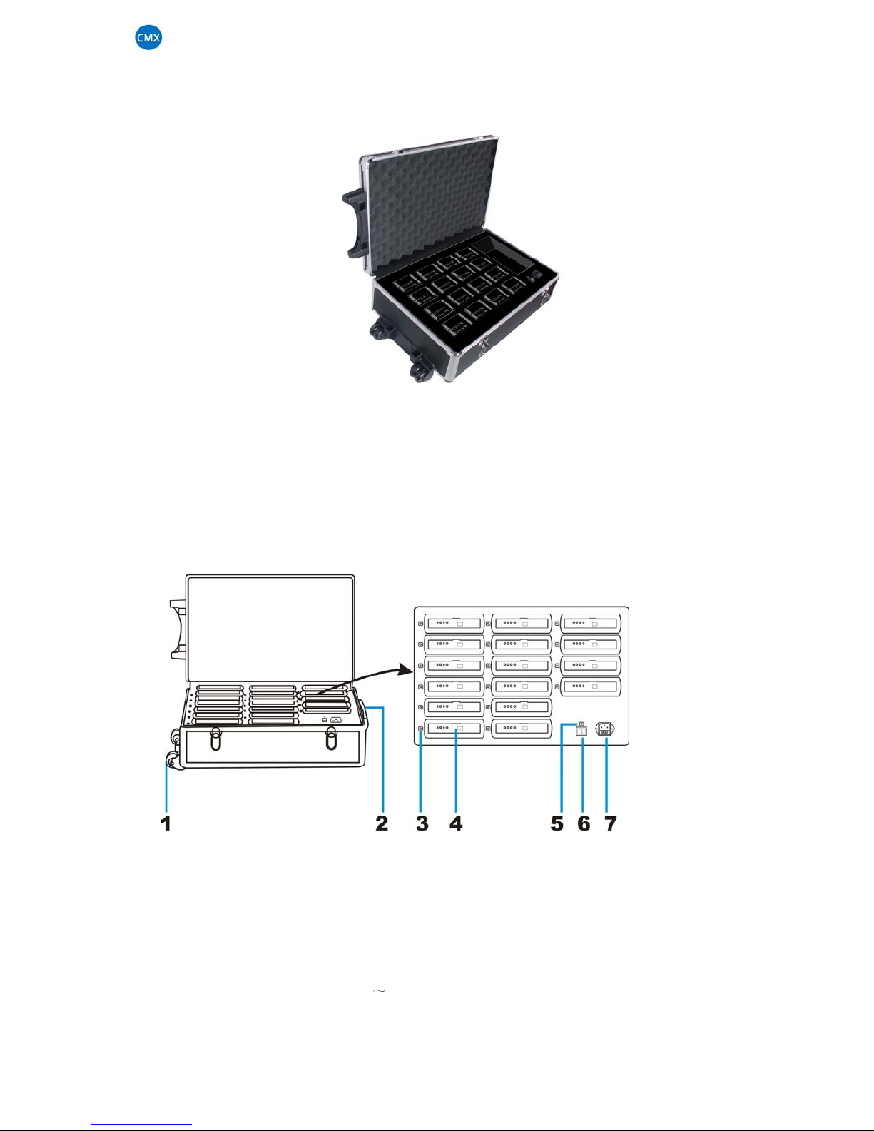
1.4 Battery charger -----------------------------------------------------------------------7
1.4.1 Picture of the actual object -----------------------------------------------------------7
1.4.2 Features of battery charge------------------------------------------------------------7
1.4.3 Schematic diagram of battery charge------------------------------------------------7
1.4.4 Parameter of battery charge ---------------------------------------------------------8
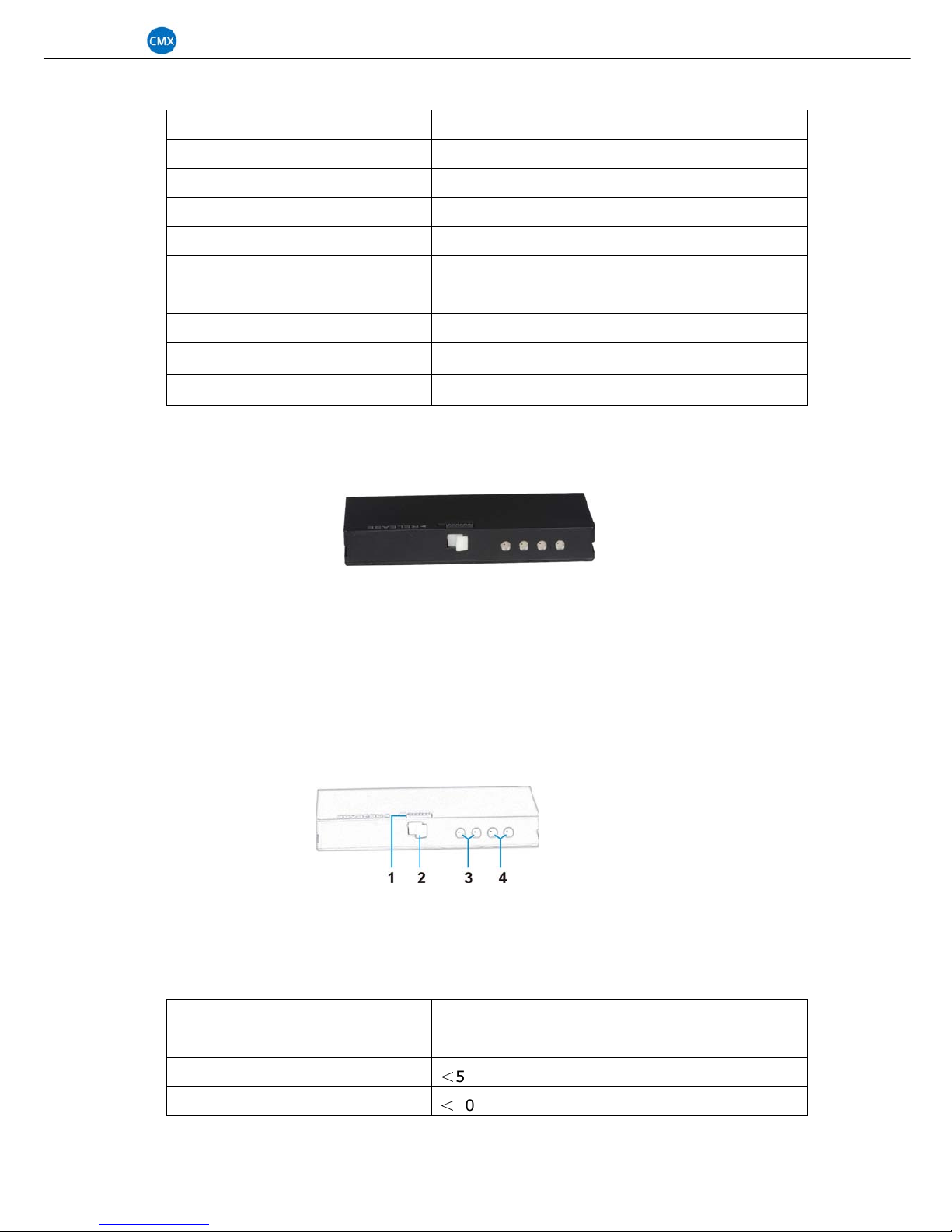
1.5 Wireless meeting system Lithium battery -------------------------------------------8
1.5.1 Picture of the actual object------------------------------------------------------------8
1.5.2 Features of Lithium battery-----------------------------------------------------------8
1.5.3 Schematic diagram of Lithium battery------------------------------------------------8
1.5.4 Parameter of Lithium battery---------------------------------------------------------9
2. System installation-------------------------------------------------------------------9
2.1 Warning-------------------------------------------------------------------------------9
2.1.1 CAUTION on handling of the microphone unit---------------------------------------10
2.1.2 CAUTION on battery charger handling----------------------------------------------10
2.1.3 CAUTION on battery handing--------------------------------------------------------10
2.2 Identify room layout-----------------------------------------------------------------11
2.2.1 Check coverage area-----------------------------------------------------------------11
2.2.2 System configuration----------------------------------------------------------------11
2.3 Installation and connection of receiver unit-----------------------------------------11
2.3.1 Receiver unit installation------------------------------------------------------------11
2.3.2 Antenna connection------------------------------------------------------------------12
2.3.3 Receiver unit to sound system------------------------------------------------------12
2.3.4 Receiver unit to video processor-----------------------------------------------------13
2.3.5 Receiver unit to external antenna---------------------------------------------------13
2.4 Installation of ireless microphone unit--------------------------------------------13
2.4.1 Mounting and dismounting the battery----------------------------------------------13
2.4.2 Mounting and dismounting the microphone-----------------------------------------14
2.5 System setting-----------------------------------------------------------------------14
2.5.1 Receiver unit setting-----------------------------------------------------------------14
2.5.2 Microphone setting and operation---------------------------------------------------17
2.5.3 USB recording module---------------------------------------------------------------18
3. Troubleshooting----------------------------------------------------------------------20

UHF-300 Wireless Conference Syste
2
Overview
With high flexibility and reliability, our UHF-300 ireless conference system is an ideal
choice for mobile conference systems. It offers simple operation, compact structures. The
ireless conference system can be perfectly integrated into any meeting rooms, ithout
additional iring. It’s the best ireless conference solutions for small-scale conferences.
1. System Configuration and description
Wireless meeting system receiver unit UHF-300MC, ireless chairman microphone
UHF-300CU, ireless delegate microphone UHF-300DU, battery charger UHF-300BC, etc.
1.1 System features
Support Mode: Limit (1/2/3/4), FIFO (1/2/3/4), Chairman Only, microphones in one
system up to 256 units, 5 microphones can be turned on at the same time.
Microphones can be operated on either their built-in rechargeable batteries. Battery
life approx. 8 hours during speech and approx. 30 hours hen standby.
Wireless communication system eliminates the need of connecting the conference
units. Installation can be done quick and smart ithout cumbersome arrangements.
Adopt multi-channel high band and intermediate band frequency selective filtering,
fully eliminate interference signal
Built-in feedback eliminating technology hich can decrease the feedback and nois
e effectively
Built-in multiple noise detecting circuit and TONE-LOCK system to make sure the
system has strong anti-jamming function
Operation distance up to 100 meters ith the best condition, 60 meters in normal
condition.
Support video camera auto-track function ith video processor
Built-in recording module to record and play audio
1.2 Wireless meeting system receiver unit UHF-300MC
1.2.1 Picture of the actual object

UHF-300 Wireless Conference Syste
3
1.2.2 Features of wireless meeting system receiver unit UHF-300MC
Support Mode: Limit (1/2/3/4), FIFO (1/2/3/4), Chairman Only
Support video camera auto-track ith video processor
160x32 dot matrix LCD display system information
Receiver can control the microphone status hen po ered off, such as clear or
shutting off all microphones.
Designed accordance to UL, CE and RTTE standards
Built-in USB recording module
Installation: 19-inch frame
1.2.3 Schematic diagram of wireless meeting system receiver unit UHF-300MC
①
Po er s itch
②
RF/Audio Level indicator ( First channel only for chairman mic, the last four channels
for delegate mic)
③
Volume knob of chairman microphone (Channel 1)
④
Volume knob of delegate microphone (Channel 2)
⑤
Volume knob of delegate microphone (Channel 3)
⑥
Volume knob of delegate microphone (Channel 4)
⑦
Volume knob of delegate microphone (Channel 5)
⑧
Do n: Setting key/check channel frequency
⑨
Menu
⑩
Up: Setting key/check channel frequency
11
LCD (Display current mode, frequency point of each channel)
12
Function Key of Recording Module: Four function key of recording module:
PLAY/STOP, PREVIOUS, NEXT, MENU
13
LCD display: To display current ork mode of the recording module
14
USB INTERFACE: Be connected to USB drive for record and display the audio

UHF-300 Wireless Conference Syste
4
15
ANT DATA: System data control antenna interface
16
DATA: External video processor connection interface
17
DC Po er input
18
MIX OUT: Mixed audio output
19
MIX BAL: Mixed audio balance output
20
ANT B: Delegate mic RF antenna interface
21
ANT B: Delegate mic RF antenna interface
22
ANT A: Chairman mic RF antenna interface
23
Microphone Speaker on/off s itch
24
Audio in interface
25
ANT: Microphone speaker audio RF antenna interface
1.2.4 Parameter of wireless meeting system receiver unit UHF-300MC
Items Parameter
Audio channel
Transmission method UHF Wireless (t o ay)
Audio channel 5 (1 chairman,4 delegate)
Carrier frequency band 610MHz~665MHz
Modulation method FM
Receiving sensitivity -100dBM
Audio gain ≤20
Frequency response 50Hz-15KHz
S/N Ratio
>
85dB
T.H.D.
<
0.8%
Data control
channel
Transmission method Wireless (t o- ay)
Data channel 16
Frequency Range 422.4MHz ~ 438.4MHz
Modulation method FSK
Receiving sensitivity -100dBM
Transmission consumption ≤6dBm
Communication rate 100KBPS
Frequency deviation
<
0.002
System
Po er supply DC12~15V ≥1A
Signal covering range Radius 60 meters
Consumption Rating 7W
Operating temperature range
-10-40 degree
Dimensions 485×355×85mm
N.W 7.2kg

UHF-300 Wireless Conference Syste
5
1.3 Wireless meeting system microphone unit UHF-300CU & UHF-300DU
1.3.1 Picture of the actual object
1.3.2 Features of wireless delegate microphone UHF-300DU
Portable table moving and microphone pipe can be pull out. Extended pipe option.
Electric capacity type microphone, equipped ith indshield cover
LCD display microphone ID, battery level, microphone state, control channel, etc.
Equipped ith microphone on/off key and indicator.
Equipped ith 3 function keys to set microphone id, control channel, volume level and
battery status.
Built-in speaker and volume control
Microphone ill shut off the po er or in standby if receiver po ered off.
1.3.3 Features of wireless chairman microphone UHF-300CU
Including the functions of the delegate unit, chairman unit has other follo ing functions:
Chairman microphone can turn on any time.
If the system support video camera auto-track function, chairman microphone ID
number should be 1
Priority function: chairman can turn off delegate microphones by clear key any time
Chairman only mode: Delegate microphone can not be turned on again after
chairman microphone press priority button. The chairman need quit this mode first,
and then delegate microphone can be turned on again
1.3.4 Schematic diagram of wireless microphone
1) Unidirectional electret MIC
2) Annular red indicator lamp to sho the microphone state.
3) Mic volume up -/do n key
4) Mic volume +/ up key
5) Mute/Set key

UHF-300 Wireless Conference Syste
6
6) MIC ON/OFF key
7) Chairman Priority
8) LCD
9) Microphone po er s itch
10) Microphone speaker
11) DC Po er input jack
12) Phone 3.5mm input jack
13) Inner speaker volume control
1.3.5 Parameter of wireless microphone unit UHF-300CU & UHF-300DU
Items Parameter
Audio channel
Transmission method UHF Wireless (t o ay)
Audio channel 5 ( 1 chairman, 4 delegate)
Carrier frequency band 610MHz~665MHz
Modulation method FM
Maximum modulation 60KHz
Radiant po er ≤+9dBm
Frequency deviation
<
0.002
Frequency response 50Hz-15KHz
S/N Ratio
>
85dB
T.H.D.
<
0.8%
Data control
channel
Transmission method Wireless (t o- ay)
Data channel 16
Frequency Range 422.4MHz ~ 438.4MHz
Modulation method FSK
Receiving sensitivity -100dBM
Transmission consumption ≤6dBm
Communication rate 100KBPS
Frequency deviation
<
0.002
System
Po er supply DC 12V
Signal covering range Radius 60 meters
Consumption Rating
Standby: ≤360mW
Speaking: ≤630mW
Operating temperature range
-10-40 degree
Dimensions 170×58×120mm
N.W 0.7kg

UHF-300 Wireless Conference Syste
7
1.4 Battery charger UHF-300BC
1.4.1 Picture of the actual object
1.4.2 Features of battery charger UHF-300BC
a. Input Voltage: AC 110V~220V
b. Charges 16 PCS of lithium battery per charging
c. Intelligent charging management electro circuit to protect the LIP battery
d. Equipped ith extendable handle and pulley, easy for moving.
1.4.3 Schematic diagram of battery charger UHF-300BC
1) Pulley
2) Extendable handle
3) Charging status indicator LED
4) Battery holder
5) Po er indicator
6) Po er on/off s itch
7) AC adapter jack (AC110V-220V
~
50Hz-60Hz)

UHF-300 Wireless Conference Syste
8
1.4.4 Parameter of battery charger UHF-300BC
Items Parameter
Po er supply 110V-240V/50Hz~60Hz
Consumption Rating 200W
Charge quantity 16
MAX charging current of each 700mA
Charging time About 8~10 hours
Charging status Red LED flashing –Charging, Green LED –Full
Operating temperature range 0-40 degree
Dimensions 620×370×175mm
N.W 9kg
1.5 Wireless meeting system LIP battery UHF-300LB
1.5.1 Picture of the actual object
1.5.2 Features of Lithium battery UHF-300LB
a. Excellent safety performance, light eight & High capacity ratio.
b. Improved safety: more resistant to overcharge; less change for electrolyte leakage.
c. The battery life is usually approximately 300 charge cycles.
d. Easy to install
1.5.3 Schematic diagram of LIP battery UHF-300LB
1) Battery detach/lock button
2) Negative
3) Positive
1.5.4 Parameter of Lithium battery UHF-300LB
Items Parameter
Rated voltage DC12V
Discharge current
<
500mA
Charging current
<
700mA

UHF-300 Wireless Conference Syste
9
Time of speaking
>
16 hours
Time of standby
>
48 hours
Charging voltage DC15V
Dimensions 130×75×20mm
N.W 250g
2. UHF-300 Wireless Conference System Installation
2.1 Warning
This is a ireless communication system, use UHF band carrier frequency. We
recommend that users consult local radio management committee to choose the
appropriate and legally available frequency, in order to avoid RF interference
If the units demonstrate any problems, such as abnormal sound, smoke, heat from or
damage to po er cables, disconnect the po er plug from the outlet and contact your
sales representative.
If the po er plug blades are distorted or discolored, do not use the unit
(Receiver unit, Battery charger)
Uncoil the po er cables before use, Do not bundle the cables during use, or fie ith
nails. (Receiver unit, Battery charger)
Do not pull on the cable. Hold the plug section and insert/remove it in a straight line,
damaged cables may result in electric shock, malfunction, or fire.
(Receiver unit, Battery charger)
Do not place anything on the po er cables. Do not route them under a rug or
furniture.
(Receiver unit, Battery charger)
Do not cover the units ith cloth or place them in locations ith poor ventilation.
Doing so traps heat, and may result in electric shock or fire
If you do not use the units for long periods of time, disconnect the po er plugs from
the outlet
(Receiver unit, Battery charger)
Do not disassemble the units. Touching the inside of the units may result in electric
shock
Do not expose the units to any strong shock
Do not expose the units to direct sunlight, heat from heating appliances, high
temperatures, or dust
Do not expose the units to high humidity or moisture
Water that accidentally enters the inside of the units may result in electric shock,
malfunction, or fire
Do not touch the po er cables or plugs ith et band
(Receiver unit, Battery charger)
Main unit is a class I device. Be certain to connect to an AC outlet ith a protective
grounding connection
Main unit can be separated from the AC receptacle by turning off the unit by the front
po er s itch. In case of emergency, turn off this s itch or unplug the po er cable
from the AC receptacle

UHF-300 Wireless Conference Syste
10
2.1.1 CAUTION on handling of the wireless microphone unit
Do not grasp the microphone to lift or pull on the microphone unit: pick up the unit by
its base
Slo ly bend and straighten the flexible part of the microphone. Do not bend it ith
excessive force
Do not drop the unit
If you do not use the unit for long periods of time, remove the battery
The dedicated lithium-ion battery should be used
Do not place any obstructions around the microphone units
When the microphone units are too close together, high sound volume may cause
acoustic feedback, In this case, increase the space bet een the conference units or
turn do n the volume
After the battery has been removed and replaced, confirm that the po er LED turns
off
2.1.2 CAUTION on battery charger handling
If the charging terminal is dirty, poor contact ill prevent the battery from being
charged properly. Periodically clean the charging terminals
The battery charger may become hot during charging. Use it in a ell-ventilated area
After the battery is fully charged, turn off the battery charger or remove the batteries
2.1.3 CAUTION on battery handling ( optional)
The battery is dedicated to the microphone unit. Do not use it for other applications
Use only the designated battery charger
If the battery leaks and the liquid contacts your skin or clothing, immediately flush
ith clean ater
If the battery leaks and the liquid contacts your eyes, immediately ash thoroughly
ith clean ater and seek medical assistance
Do not thro the battery into fire or overheat it, Doing so may result in a fire
Do not disassemble or modify the battery
Do not short-circuit the + and – terminals ith any metal or ire. Do not carry or
store the battery ith metal products such as a necklace.
If you discover battery leaks, discoloration, distortion, or the other problems, do not
use the battery
Dispose of used batteries properly as industrial aste or contact our business office in
your neighborhood

UHF-300 Wireless Conference Syste
11
2.2 Identify room layout
2.2.1 Check coverage area
Real coverage area of conference room (usually coverage area of conference room is
smaller than the conference room area)
2.2.2 System configuration
Description Model No. Max Qty Marks
Receiver Unit 1
Chairman Microphone 1
Delegate Microphone ≤999
Data Control Antenna 1
Audio Control Antenna
3
Battery Charger
LIP Battery
2.3 Installation and connection of receiver unit
2.3.1 Receiver unit installation
a. Put on the table or install in 19 inch frame
b. Please keep a ay from high-po er and strong radiation equipments, or it may
influence the equipment performance.
c. Use it in a ell-ventilated area

UHF-300 Wireless Conference Syste
12
2.3.2 Antenna connection
There are 4 antennas of receiver unit. 1 piece data control antenna (426MHz), 1 piece
chairman microphone audio control/RF antenna (A: 627.50MHz) and 2 pieces delegate
microphone audio control/RF antenna (B: 652.50MHz)
Please note: Receiver antennas should be connected correct position, or system can
not ork properly.
2.3.3 Receiver unit to sound system
a. Mono output: Please connect MIX OUT interface of receiver unit to input interface of
sound equipment by Φ6.3 audio cable (for short distance)
b. Balance output: Please connect MIX-BAL interface of receiver unit to input interface of
sound equipment by XLR-M balance audio cable ( for long distance)

UHF-300 Wireless Conference Syste
13
2.3.4 Receiver unit to video processor
Please connect DATA interface of receiver unit to DATA interface of video processor by
RJ45 net ork cable. Please read the user manual of video processor.
2.3.5 Receiver unit to external antenna
If the distance bet een receiver and microphone is not far, and there does not have any
obstruct, antenna can be connect to the “ANT” interface of receiver unit rear panel directly.
If the distance is far or have some obstruct bet een them, please connect external
antenna to receiver unit.
Please note: coaxial cable should be 50Ω.
2.4 Installation of wireless microphone unit
2.4.1 Mounting the battery
a. Mounting battery: Put the battery on the bottom side of the microphone unit; slide the
battery in the direction of the arro to fasten it.
*Listen for the click sound and make sure the battery is securely inserted.
b. Dismount battery: Slide the battery in the direction of the arro and pull it out by
pushing the battery removal button.
2.4.2 Mounting and dismounting the microphone
a. Mounting microphone: Insert the microphone into the microphone mounting socket in
a straight line
b. Dismounting microphone: Pull the microphone up ard to dismounting
* Please contact us if you need more detailed information during your installation.

UHF-300 Wireless Conference Syste
14
2.5 Wireless Conference System setting
2.5.1 Receiver unit UHF-300MC setting
a. POWER ON/POWER OFF
POWER ON: Hold the “POWER” button on the left front panel of receiver till LCD
display “ “ and then release it LCD ill display “ “, after
system self-detecting LCD ill display “ “
POWER OFF: Hold the “POWER” button on the left front panel of receiver till LCD
display “ “, receiver unit ill po ered off and all microphones in standby
status hen released the button. If still hold the button, LCD ill display
“ “, both receiver and microphones are po ered off at the same time.
a. System function key: There are 3 function keys on receiver unit
DOWN SET UP
b. System mode setting:
System default mode: CFREE-4MAX-FIFO
System support 10 modes setting by receiver unit (FIFO 1/2/3/4, LIMIT 1/2/3/4,
CONLY, CFREE), user can set these mode by UP & DOWN key. System ill save and
keep the last setting mode in 3 seconds automatically or press SET key to save the
mode immediately.
C.ONLY: When chairman microphone priority button as press on, the chairman
microphone is turn on hile the delegate microphone being turn off until the priority
button is released, or delegate microphone can not turn on again.
Mode setting method: Press SET key one or several times till “CFREE” character
flashing, press DOWN, the flashing character ill change to CONLY (press UP the
flashing character ill change to CFREE), and then press SET to save it or ait about
3 seconds the system ill save the mode automatically, characters ill stop flashing.
C.FREE: When chairman microphone priority button as press on, the chairman
microphone is turn on hile the delegate microphone being turn off, but delegate
microphone can be turned on again even chairman microphone not released priority
button.
Mode setting method: please see C.ONLY setting method
1MAX-LIMIT: System only allo ed 1 piece delegate microphone turned on at the
same time, if other delegate microphones ant turn on, user should turn off that
microphone first.
Number setting method: Press SET key one or several times till “4MAX” character
flashing, press DOWN or UP key till the flashing character change to 1MAX, and then
press SET to save it or ait about 3 seconds the system ill save the setting
automatically, characters ill stop flashing

UHF-300 Wireless Conference Syste
15
Mode setting method: Press SET key one or several times till “FIFO” character
flashing, press UP key, the flashing character change to LIMIT (press DOWN the
flashing character ill change back to FIFO), and then press SET to save it or ait
about 3 seconds the system ill save the setting automatically, characters ill stop
flashing.
2MAX-LIMIT: System only allo ed 2 pieces delegate microphones turned on at the
same time, if other delegate microphones ant turn on, user should turn off 1 or 2
microphones first.
Setting method: please see 1MAX-LIMIT setting method
3MAX-LIMIT: System only allo ed 3 pieces delegate microphones turned on at the
same time, if other delegate microphones ant turn on, user should turn off 1, 2 or 3
microphones first.
Setting method: please see 1MAX-LIMIT setting method
4MAX-LIMIT: System only allo ed 4 pieces delegate microphones turned on at the
same time, if other delegate microphones ant turn on, user should turn off 1, 2, 3 or
4 microphones first.
Setting method: please see 1MAX-LIMIT setting method
1MAX-FIFO: System only allo ed 1 piece delegate microphones turned on at the
same time, if other delegate microphone turns on, system ill turn off the first on
microphone automatically. First in, first out, first indicate, first offer.
Setting method: please see 1MAX-LIMIT setting method
2MAX-FIFO: System only allo ed 2 piece delegate microphones turned on at the
same time, if other delegate microphone turns on, system ill turn off the first on
microphone automatically.
Setting method: please see 1MAX-LIMIT setting method
3MAX-FIFO: System only allo ed 3 piece delegate microphones turned on at the
same time, if other delegate microphone turns on, system ill turn off the first on
microphone automatically.
Setting method: please see 1MAX-LIMIT setting method
4MAX-FIFO: System only allo ed 4 piece delegate microphones turned on at the
same time, if other delegate microphone turns on, system ill turn off the first on
microphone automatically.
Setting method: please see 1MAX-LIMIT setting method
Please note: Chairman microphone is not limit in these mode, chairman microphone
can be turned on and off independently.
c. System audio channel setting
System default audio channel: 40[05-35-65-95]

UHF-300 Wireless Conference Syste
16
Chairman microphone audio channel
Manual setting: Press SET key one or several times till “40” character flashing,
press DOWN or UP key to select the channel, and then press SET to save it or
ait about 3 seconds the system ill save the setting automatically, characters
ill stop flashing
Auto-scan setting: Press SET key one or several times till “40” character flashing,
and then press and hold the SET key till LCD display symbol ---, release the key,
system ill scan all audio channel (00-99) automatically and select the best one
to save it.
Chairman microphone audio description: Band idth of chairman microphone is
25M; default setting is 610.00MHz -- 634.75MHz (Please contact us or agent to
get more information if user ant choose other frequency for chairman
microphone). There are 100 channels for option in this band idth, frequency
interval is 250 KHz.
Delegate microphone (D1, D2, D3, D4) audio channel
Channel setting method: please see chairman microphone audio channel setting
method.
Delegate microphone audio description: Band idth of delegate microphone is
25M, default setting is 640.00MHz -- 664.75MHz (Please contact us or agent to
get more information if user ant choose other frequency for delegate
microphone). There are 100 channels for option in this band idth, frequency
interval is 250 KHz.
Please note there are 4 audio channel of the delegate microphone in the system,
so the channel number can not be same.
d. System project setting
Press SET key and turn on the receiver ith POWER key at the same time, receiver LCD
ill display , there are 4 setting menu in this part.
Receiver data (room) channel setting (Default channel is "ROOM 1"), there are 16
data (room) channel for option (0-1-2-3-4-5-6-7-8-9-A-B-C-D-E-F), user can select
the channel by UP and DOWN key, and press SET to save the setting, receiver ill
s itch to next setting part automatically. This system use room number to sho the
data control channel, if there are more than 1 system used in the same place or
building, e suggest user to set different room number (data channel) in order to
avoid interface. If other equipments has same frequency of the data channel, use also
can change it.
Delegate microphone audio channel: the receiver ill s itch to delegate microphone
audio channel setting automatically after user save the setting of receiver data
channel.
0---Audio channel not available, 1---Audio channel not available.
Setting method of Channel 1: Press DOWN key to close this channel and press
UP key to open this channel, press SET key to save the setting and receiver ill
s itch to next setting part automatically.
Setting method of channel 2, 3, 4: Please see the setting of channel 1.
Description of this setting: Receiver use 4 channel LNB to support 4 delegate

UHF-300 Wireless Conference Syste
17
microphones' FM high frequency signals. Default sort order is D1, D2, D3, D4. If
there is some problem of D1, then system microphone can not turn on/off
properly, user can set this channel not available, then receiver LNB default sort
order is D2, D3, D4, and only support 3 delegate microphones orking at the
same time maximum. This setting just for urgently situation, please contact local
agent or us to get the solution.
Hold and press SET key/press POWER key till LCD display to exit
the project setting.
f. System lock & unlock
Lock setting method: Press and hold the SET key first, and press UP key at the
same time, system LCD ill display
Unlock setting method: Press and hold the SET key first, and press DOWN key at
the same time, system LCD ill display
Please note if the system locked, the function keys on the receiver panel are not
available to used for setting.
g. Checking system audio and data channel
User can check the system audio and data (Room) channel by UP and DOWN key
User can check the chairman microphone (C) and delegate microphones ( D1, D2, D3,
D4) audio channel, data (room) channel, frequency point even the system locked.
We recommend user to use auto-scan function if any interference in each channels.
System ill shut off all microphones (include chairman microphone) if user save the
setting.
If the system can orking properly after testing, e strongly recommend user to lock
the system setting.
2.5.2. UHF-300CU & UHF-300DU Microphone setting & operation
There are 3 function keys on microphone unit ( Include chairman microphone):
POWER, ON/OFF, PRIOR, VOL-, VOL +, MUTE
a. Microphone function key description:
POWER: Press this key to po er on or po er off the microphone
ON/OFF: Microphone ill on/off in correct communication mode ( If the microphone
data channel is different from receiver data channel, user can not turn on the
microphone.
PRIOR: Chairman microphone priority key, it can turn off all delegate microphone
ith this key.
VOL-: Decrease the volume level of microphone
VOL+: Increase the volume level of microphone
MUTE: Prevention on speaker's cough
b. Microphone project setting
Press MUTE key and turn on the microphone ith POWER key at the same time,
microphone ill enter project setting. There are four setting in this part.
Microphone data (room) channel setting (Default channel is "ROOM 0"), there are 16
data (room) channel for option (0-1-2-3-4-5-6-7-8-9-A-B-C-D-E-F), user can select

UHF-300 Wireless Conference Syste
18
the channel by VOL - and VOL + key, and press MUTE to save the setting,
Microphone ill s itch to next setting part automatically. User can see receiver data
channel setting for reference.
Microphone ID setting: Chairman microphone ID number can be set from 0-9, A-F
total 16 ID for option, delegate microphone ID number can be set from 0-255, total
156 ID for option. User can select the ID by VOL - and VOL + key, and press MUTE
to save the setting, Microphone ill s itch to next setting part automatically.
Please note: All microphone ID in one system should be different, if any units have
the same ID number, the system ill not ork properly. If system connect video
processor to support video camera auto-track function, chairman microphone ID
should be 1.
Chime of chairman microphone: When chairman microphone turned on, system ill
give a chime indicative sound. User can press VOL - to close this function and press
VOL + to open this function.
Microphone orking mode: Default mode is LINK. User can press VOL - s itch to
FREE mode and press VOL + s itch to LINK mode. In Free mode, microphone can be
tuned on/off any time ith communicate ith receiver unit, and user can set the
microphone audio channel ( hen microphone is off, press MUTE key, audio channel
number ill flash, user can press VOL - and VOL + key to select the audio channel),
FREE mode just used for testing. In LINK mode, microphone must ork and
communicate ith receiver unit, or microphone can not turn on, microphone audio
channel as distributed by receiver unit.
Exit microphone project setting: Press microphone on or POWER key to exit, if there
is no action of the microphone microphone ill exit the setting in 9 secs.
2.5.3.USB RECORDING MODULE
USB recording module menu include 5 sub-menu
Operation method:
•
Press “ / ” to select the sub-menu.
•
Press “ ” to enter the sub-menu.
•
Press “ ” to exit current menu and back to previous menu.
•
Hold and press “ ” 3 seconds back to the main menu
①
Music: The device ill play the audio file (mp3 format) automatically hen USB
flash disk connected USB interface, and user can select the audio file by press
key “ / ”

UHF-300 Wireless Conference Syste
19
Function key instruction:
Function Key Instruction
PLAY/PAUSE
Short press
:
Play/Pause
Long press: Sub-menu s itch interface (MSC/REC/BT/SYS/UDI)
PREV PREV / V-: Short press for previous audio file, long press for decrease
volume
NEXT NEXT/ V+: Short press for next audio file, long press for increase
volume
MENU
Built-in sub-menu: U-disk folder/EQ/Play mode
Long press: Enter recording mode
②
Record: In this interface the record module can record the audio of the system,
press key “ ” to start recording, please key “ ” again to pause recording,
press “ ” to exit recording and play the record file automatically.
The record file ill save in the folder named “ Record”, the file format is *.mp3
③
Bluetooth: In this interface user can use other Bluetooth device ( such as mobile
phone) to connect it and play the audio, system Bluetooth device name “NLJ-BT
In Bluetooth interface, user can enter the Bluetooth function by press key “ ” and
check all information ith key “ / ”
④
UDI: User can connect computer or other devices to USB interface to play the
audio file
⑤
Setting: User can set the system function by press key “ / ” in this interface
Back-light time: To set LCD back-light time (00-240 Seconds)
Language: To set display language
Contrast: The set LCD display contrast (Level 0-20)
Version: To display device version
Exit
Table of contents
Other CMX Conference System manuals
Popular Conference System manuals by other brands

TANDBERG
TANDBERG 150 MXP user guide

Cisco
Cisco DX650 quick start guide

Lucent Technologies
Lucent Technologies PARTNER Advanced Communications System Release... Programming and use instructions

Polycom
Polycom CX5000 Setup guide

Metz Connect
Metz Connect BTR Netcom E-DAT C6 Series Termination instructions

Crestron
Crestron UC-C160-Z quick start guide