Vertex Water Products EasyPur Water Machine EZ-575 User manual

VERTEX WATER PRODUCTS
EZ-575
VERTEX
Water Products
EasyPur
Water Machine
OWNERS MANUAL
™
REVERSE OSMOSIS UNDERSINK
WATER FILTRATION SYSTEM

Table of Contents
i . Notice
ii. Parts List
1 . 0 Introduction . . . . . . . . . . . . . . . . . . . . . . . . . . . . pg. 1
2.0 Receiving . . . . . . . . . . . . . . . . . . . . . . . . . . . . . pg. 2
2.1 Location of RO Unit . . . . . . . . . . . . . . . . . . . . . . . . .pg. 2
2.2 Mounting the RO filter Unit Under a Sink . . . . . . . . . .pg. 2
2.3 Connecting the Feed Water Supply . . . . . . . . . . . . . . . .pg. 4
2.4 Installation of Drain Connection . . . . . . . . . . . . . . . . . .pg. 5
2.5 Installation of Clean Water Faucet . . . . . . . . . . . . . . . . .pg. 5
2.6 Porcelain/Enamel Over Steel or Cast Iron Sinks . . . . . . .pg. 6
2.7 Install Faucet . . . . . . . . . . . . . . . . . . . . . . . . . . . . . . .pg. 6
2.8 Tubing Connections . . . . . . . . . . . . . . . . . . . . . . . . . .pg. 7
2.9 Air Gap Faucet Installation . . . . . . . . . . . . . . . . . . . . .pg. 8
3.0 System Start Up . . . . . . . . . . . . . . . . . . . . . . . . . pg. 9
3.1 Air Purge . . . . . . . . . . . . . . . . . . . . . . . . . . . . . . . . .pg. 9
3.2 Start-up . . . . . . . . . . . . . . . . . . . . . . . . . . . . . . . . . . .pg. 9
4.0 Recommended Filter Changes . . . . . . . . . . . . . . . . . pg. 10
5.0 Filter Replacement Changes . . . . . . . . . . . . . . . . . . pg. 11
6.0 Installation Troubleshooting . . . . . . . . . . . . . . . . . pg. 11
7.0 Conditions of Use . . . . . . . . . . . . . . . . . . . . . . . . pg. 12
8. 0 Product Warranty . . . . . . . . . . . . . . . . . . . . . . . . . pg. 12
9.0 Performance Data Sheet . . . . . . . . . . . . . . . . . . . . pg. 13
Appendix A: Theory of Operation . . . . . . . . . . . . . . . . .pg. 14
The VERTEX EasyPur Water Machine is made with quality components to
provide cleaner, safer drinking water. No chemicals are added or used in
this system. To preserve the filter capability, it is a must that the filter
replacement be made at the intervals and with replacement elements as
specified in section 4.0 of this manual.
WQA GOLD SEAL APPROVAL: The EasyPur Water Machine has been tested
and certified by the Water Quality Association according to ANSI/NSF 58
for the specific performance claims as verified and substantiated by test
data. See the Performance Data Sheet, page 13.

i. NOTICE
This instruction manual was written to guide a professional plumber to make an
easy installation of the Vertex EasyPur Water Machine™. The installation must
comply with state and local laws and plumbing codes.
This filter system can be installed by the homeowner who has suffi-
cient tools and skills. Be cautioned that an extra faucet for purified water will be
installed. This requires a 7/8-inch diameter hole in the sink top. If there is not an extra
hole existing, a new one must be drilled. For a porcelain sink, this requires a special
drill (7/8" Relton cutter) which costs about $150 and requires skill to use.
ii. PARTS LIST
PARTS CONTAINED IN THE EasyPur Water Machine™ CARTON
1– Box containing storage tank
1 - Box with filter assemblies
1 - Set of 1/4” and 3/8” tubes, orange, white, black, yellow
1—Clean water faucet and fittings
1—Set of hardware consisting of:
Inlet water 1/4” ball valve and 1/2” feed line adapter
3/8” plastic ball valve for tank shutoff
Drain saddle clamp
1.0 INTRODUCTION
The Vertex EasyPur Water Machine™ is a 5-stage water cleansing system. The
principal cleansing of the water of its dissolved solids is by the Reverse Osmosis
membrane filter (stage 4).
Stage One is a sediment filter which removes particles of rust, sand and other
trash in the water line down to 5-microns in size.
Stage Two and Three are activated carbon block filters which remove odors, chlo-
rine and foreign tastes.
Stage Four is an advanced reverse osmosis membrane for removal of dissolved
solids. This is the heart of the system. The reverse osmosis technology removes 95%
of the dissolved solids on average. Dissolved solids are not removed by municipal
water treatment. That is why the Vertex EasyPur Water Machine™ is an impor-
tant safety factor for the water you drink and use in your cooking. Chemical conta-
minants such as mercury, lead, nitrates, pesticides and others not yet identified which
seep into municipal water systems are removed. Bacteria such as cryptosporidium,
giardia lamblia, and others yet unknown are removed.
The water pressure against the reverse osmosis membrane forces the water mol-
ecules through the membrane, but the larger contaminant molecules and bacteria are
kept behind and are flushed to the sewer. The clean water goes to the storage tank and
is held there ready to use.
Stage Five is a Carbon polishing filter to remove any foreign tastes or odors that
may occur from storing the water. When the faucet is opened, clean water from the
storage tank flows through the final polishing filter (Stage Five) of activated carbon
and into the faucet for your use. The tank is pre-pressurized with a bladder which
pushes the water out through Stage Five to the faucet.
A special faucet is installed on your sink which dispenses safe, good tasting
drinking water, which is especially good for coffee, tea and drinks. By extending a line
to your refrigerator, it can be used to make ice cubes.
LIFE. The filter life is specified by the number of gallons of water flowing
through the system. Normal household will use two to three gallons of purified water
daily. The filters are good for 1500 to 3000 gallons total usage. The Reverse Osmosis
membrane has a longer effective life-span (5-Year Maximum) and should be changed
once every 4 years.
– 1 –

2.0 Installation
2.1 Location of RO Unit
The RO unit may be located under the kitchen sink or in the basement. A cold water
supply line must be close by. When locating the system under a sink make sure there is
adequate room for the filter module assembly as well as the storage tank. For best perfor-
mance the tank should be located as close to the clean water faucet (supplied) as possible
(within 20 feet).
2.2 Mounting the RO filter unit under a sink (Fig. 1)
Mount the unit to the wall of the sink cabinet. Pre-fit the unit by positioning the bot-
tom of the pre-filer cartridges 2 inches off the floor of the cabinet. This clearance is neces-
sary to make room to move the housing when replacing the filter cartridges. Mark the loca-
tion of the 2 mounting holes in the mounting bracket. Install 2 mounting screws leaving
1/8 inch clearance under the screw head. Check the fit by mounting the RO filter unit but
don’t install yet.
A 1/4” ball valve is supplied so the homeowner can easily shut off feed water when leav-
ing the home unattended as shown in Figure 1. An automatic water sensor and shutoff valve
(battery powered) is available form Vertex to protect the system (P/N LC-8021). The best
overall protection from potential water leaks in the kitchen, hot water heater, or utility room
is to install an automatic leak detector shutoff valve to the house (Vertex P/N LC-8049).
– 2–
Optional Main Water Shutoff
P/N LC-8049
– 3 –
Figure 1
Figure 2

– 4 –
2.3 Connecting the feed water supply (Figure 3, 4)
The feed water assembly consists of 1/2” brass slip joint adapter, a black washer, and
a 1/4” x 1/4” ball valve. Locate these parts in the installation kit.
Locate the cold water shut off valve under the sink and turn it off. Open the cold water
faucet to release the pressure. On single handled faucets, the hot water may have to be
turned off to prevent any hot water cross-over. If water continues to come out of the faucet
with the under-sink valves turned off, the house main valve will have to be turned off.
Now that the water has been turned off, disconnect the cold water riser tube (flex line)
from the valve. Install the slip joint connector with the black washer. Loosen the nut and
separate the cold riser tube from the faucet shank. Gently bend the riser tube so that the
slip joint adapter fits onto the faucet shank. Reinstall the cold riser tube on the slip joint
connector using the existing cone washer. For Solid copper tube the procedure is the same
except you must cut a piece of the riser tube about 3/4” to 1” so the slip joint adapter can
fit between the valve and the riser tube. Wrap several turns of Teflon tape on the ball valve
and install on the slip joint connector. (See Figure 3).
In some cases the EasyPur Water Machine™ is supplied with a saddle Valve which
can clamp over a copper pipe and make the hole and seal at once. (See Figure 4).
Figure 3 Figure 4
2.4 Installation of drain connection (Figure 5)
Place the drain outlet saddle on the drain pipe. Allow proper space for the drilling
operation. Tighten the saddle bolts evenly on both sides. Using the opening in the drain
outlet saddle as a guide, drill a 1/4” hole in the drain pipe. Clean any debris out of the
drain saddle connection.
2.5 Installation of clean water faucet (Fig. 6)
The faucet should be positioned with aes-
thetics, function, and convenience in
mind. An ample flat area is required for
the faucet base so that it can be drawn
down tight. The space under the sink
below where the faucet will be mounted
must be clear of any obstructions.
Some conditions may eliminate the need
to drill a hole in the sink such as a faucet
previously installed in the sink, a hole
covered by a chrome hole cover, or an
unused spray handle. If any of these situ-
ations are present, you may mount the
faucet in one of these holes.
– 5 –
Figure 5

[NOTE: This procedure is for the non
air gap faucet provided.]
2.6 Porcelain/Enamel over Steel or Cast Iron Sinks
Using a small diameter carbide tipped drill, drill a pilot hole completely through the
porcelain and the material underneath. Remove any metal chips that fall into the sink to pre-
vent rust stains. Place the spring-loaded porcelain cutter bit in to the drill chuck. Make sure
the pilot guide is inserted tightly. Insert the pilot guide onto the pilot hole. Push down gen-
tly on the drill motor to apply light pressure to the porcelain surface. Start the drill motor,
turning as slowly as possible. After the initial cut has started, motor speed may be gradual-
ly increased. The cut may require three to four minutes to complete. Going faster could result
in excessive chipping. Be sure a complete ring has been cut through the porcelain to the
metal underneath.
Place the finish hole saw into the drill chuck. Make sure the pilot guide is inserted
tightly. Insert the pilot guide into the pilot hole. Begin cut using a slow speed and light
pressure until the porcelain has been penetrated to the material underneath. Remove the saw
from the hole and clean all debris from the porcelain surface. Reinsert saw into the hole and
cut through the remaining material.
2.7 Install Faucet (Figure 7)
– 6 –
Disassemble the hardware from the thread-
ed stud except for the top base plate and
sealing gasket. Install the faucet in the sink
hole. From below the sink assemble the
mounting hardware. Use a deep socket to
tighten the nut.
2.8 Tubing Connections (Figure 8)
a.
The standard tubing connections on the
EasyPur Water Machine™
are of Quick Connect
0-ring seal design and manufacture. Use the tubing and follow the instructions in Figure 8
to make the connections. If you cut the tubing, make sure it is square cut to the tubing fits
squarely in the fitting and seals properly.
– 7 –

b. Feed Water Line
Connect the orange colored 1/4” inlet tubing to the ball valve, or saddle valve
installed in step 2.3 above. To reduce the water hammer effect on this fitting, make a large
loop in the tubing before the connection on the sediment filter. To connect, remove com-
pression nut insert tube over the ball valve tube as shown in Fig. 3. Slide nut over threads
and tighten. Connect the other end of the tube to the inlet fitting using the method as
described in section 2.3
c. Drain Line
Find the black colored 1/4” tubing. Connect the tube to the drain saddle clamp from
step 2.4. Push tube into fitting about 1/2 inch. Tighten plastic nut.
d. Faucet Line
Screw on the Faucet adapter to the end of the faucet. Find the white colored 3/8” tub-
ing and insert into the quick connect fitting as described in section 2.8a. Connect the end
of the tube to the quick connect fitting on the post filter (stage 5). Push the tube into the
fitting until it stops.
e. Tank Line
Install the plastic ball valve on the storage tank. Find the yellow colored 3/8” tubing
and connect the tube to the plastic ball valve on the tank. Push tube into fitting until it
stops. Connect the other end of the yellow tube to the “T” fitting on the Post filter (stage
5). The tank comes pre-charged from the factory at 5-7 psi. Double check the pressure with
a tire gage (the air fitting is on the opposite end of the tank from the ball valve). If it is
less than 5 psi add 2 psi with a compressor or bicycle pump. Note: Putting more pressure
than 7 psi does not help to increase water flow through the faucet.
2.9 Air-Gap Faucet Installation
Air-Gap Faucets are sometimes required by municipal code. The faucet is designed to
take the waste water from the membrane to the top of the sink and then let it flow by grav-
ity to the drain saddle. The objective is to prevent possible backup of drain water from the
sink to the membrane in the event of a sink clog. A drain saddle with 3/8" instead of 1/4"
is used. An extra section of 3/8" tubing (yellow) is used from the faucet to the drain.
Sink Preparation
Drill the appropriate size hole in the kitchen sink to accommodate the air-gap faucet.
Drain Connection
Follow instructions of Section 2.5 except drill a 3/8" hole in the drain pipe.
– 8 – – 9 –
Tubing Connections
Find the black colored 1/4" drain line from the membrane. Remove from membrane hous-
ing. Connect this tube to the 1/4" barbed fitting on the air-gap faucet.
Find the 3/8" yellow tubing in the parts kit. Connect this tube to the 3/8" barbed fitting
on the air-gap faucet. Install the faucet assembly (with tubes attached) into the sink hole.
Secure the faucet per instructions in section 2.8. Re-attach the 1/4" black tubing to the
drain side of the RO membrane housing. Be sure to tighten the fitting nut securely. Attach
the 3/8" tube to the drain connector. Tighten the fitting nut securely. Attach the pure water
line to the faucet per the instructions in section 2.8 -d.
Note: To help reduce drain noise, gently curve the tubing form the air-gap faucet to the
drain connection.
3.0 System Start Up
3.1 Air Purge
The filter elements of stage 1, 2 ,3, and 5 filters as shipped are dry and contain
air in the pores. The air will slowly be expelled but may collect in the system and
will need to be purged for peak operating efficiency. Proceed with section 3.2 for air
purge and initial start-up procedure.
3.2 Start-Up
Start the system by opening the feed water ball valve. Make sure the ball valve
on the storage tank is in the closed position. Check for leaks for at least 10 minutes.
Open the product water faucet and let the water flow until all the air has been expelled
from the system. This will take about 30 minutes.
Close the product water faucet. Now open the tank valve. Let the system run about
2-hours to get a complete tankful. Then open the clean water faucet on the sink and
empty the tank. This is to flush the tank and remove the preservative from the RO mem-
brane, as well as carbon "fines" from the post filter that may have collected in the tank.
If the waste continues to run after the tank is full, it may mean there is air bind-
ing the autovalve. Empty the tank again by opening the faucet. This will help to clear
more air from the system. If the waste water running persists, remove the connection
and the stainless steel check valve at the outlet of the RO stage. Clean the check
valve, reassemble and start the system again.

4.0 Recommended Filter Changes
This system contains a replacement treatment component, the reverse osmosis mem-
brane element, which is critical to effective reduction of TDS. Replacement of the reverse
osmosis component should be with one of identical specifications, as defined here-in, to
assure the same efficiency and contaminant reduction performance. Replacement part num-
bers and changeout periods for the RO and other filter elements are shown below. The prod-
uct water should be tested periodically to verify that the system is performing satisfacto-
rily in addition to making the parts replacements specified.
To maintain the GoldSeal Certification, only these replacement parts should be used.
Recommended Changeout Interval
RO Membrane Element 75gpd, P/N MH-4206 once each 3 years
First stage sediment filter, 5-micron, P/N TF-4004 once each year
Second stage activated carbon, P/N TF-4003 once each year
Third stage activated carbon filter, P/N TF-4003 once each year
Post filter fifth stage, activated carbon, P/N IFA-4036 once each year
These filter replacement elements are available from your dealer. When you buy or
install your
EasyPur Water Machine™
filter, we recommend that you buy the first year fil-
ter replacement kit (FK-103). This includes Stage 1, 2, 3 and 5 filter elements.
This kit comes in a plastic satchel which can be attached to the installed
EasyPur
Water Machine™
under your sink. There is a space to write in the date of replacement,
which is a maximum of one year from date of installation. In the replacement kit are
instructions for replacement and cleaning,
At year 4 (or sooner if you have severe water problems), we recommend that the
Stage 4 reverse osmosis assembly be changed also. When you order your fourth year kit
from your Vertex dealer, request the RO membrane along with the other four elements.
– 10 – -11-
5.0 Filter Replacement Procedure
Turn off the feed water at the feed water ball valve. Empty at least 2.0 gallons from
the storage tank to take any back pressure off the system. Put a shallow pan under the RO
system to catch any water that may spill during the operation.
BE SURE TO CLOSE THE FEED WATER VALVE ON STAGE-1 SEDIMENT FILTER BY TURNING THE VALVE HAN-
DLE DOWN. Unscrew the filter body and carefully lift it to the sink to drain or empty the
water remaining in it. Discard spent filter body. Install new filter body cartridge. Tighten
housing securely. Repeat for all 3 pre-filters.
6.0 Installation Troubleshooting
PROBLEM CAUSE SOLUTION
• No or low water production • Feed water shut off.
• Tank valve vlosed or partially
closed.
• Low feed pressure. Feed pres
sure must be at least 40 psi.
• Turn on feed water.
• Open tank valve.
• Increase inlet water pressure
or install booster pump if feed
water pressure is less than 40
psi.
Water runs to drain all the time • Auto-valve not closing properly.
• Check-valve clogged or stuck
open.
• Purge system again.
• Clean check-valve.
• RO production good at first but
falls off in months or weeks
• High TDS and/or Iron
Manganese in water.
• Consult your dealer ot the
factory and provide water
analysis.
• Bad tasting water • Post-filter cartridge not flushed
completely.
• Flush one or two tanks of pure
water through system.
• Leak at threaded connection • Not properly installed • Remove tube and reinstall into
fitting.

-12-
7.0 Conditions Of Use
Water must be microbiologically safe. System pressure, 40 to 100 PSIG.
Temperature, 40 to 100 degrees F. PH Range, 3 to 10. Maximum TDS, 1500
PPM. Maximum Iron (Fe) 0.3ppm, Maximum Manganese (Mn) .0.1ppm,
Turbidity, less than 1.0 NTU.
8.0 Five-Year Limited Warranty
Vertex Water Products sells its products through independent water dealers
who re-sell the product to the end user.
Vertex warrants the
EasyPur Water Machine™
be free from defects in materi-
als and workmanship for a period of FIVE YEARS from the date of purchase. This
warranty does not cover damage resulting from accident, misuse, neglect,
improper installation, or subjection to water pressure in excess of 100 lbs. per
square inch. The warranty shall extend only to the original purchaser of the prod-
uct from a Vertex dealer for use by the purchaser. Any modifications of the prod-
uct shall render the warranty invalid and Vertex will have no further responsibil-
ity. All warranty claims must be made to the Vertex dealer from which the prod-
uct was purchased.
Vertex shall in no event be liable for any incidental or consequential damages
of any kind; the sole obligation of Vertex being limited to repair or replacement
of defective parts of product. Proof of purchase, date of purchase, and name of
dealer are required.
Any implied warranties herein are limited in duration to a period of five years
form the date of original purchase or the shortest period allowed by law.
-13-
9.0 Performance Data Sheet
Vertex EasyPur Water Machine™ Reverse Osmosis Water Filter System
This is a water filter system optimized to produce good drinking water for home use.
Model EZ-575
WQA GOLD SEAL APPROVAL (Water Quality Association)
This system has been tested by the Water Quality Association according to
ANSI/NSF 58 for reduction of Totally Dissolved Solids (TDS) listed below. The
concentration of the indicated substances in water entering the system was
reduced to a concentration less than or equal to the permissible limit for water
leaving the system, as specified by NSF/ANSI 58. Test results; Average Clean
Water Production Rate = 28.4gpd (31lpd) at an efficiency rate percentage of
14.2% efficiency. Efficiency rating is the percentage of influent water to the sys-
tem that is available to the user as reverse osmosis treated water under oper-
ating conditions that approximate typical daily usage. Test parameters: 25ºC,
50psig and pH of 7.5. Performance under actual conditions may vary.
Specifications
75 gallon per day reverse osmosis membrane
28 gallon per day clean water production at 50 psig inlet and at 77°F(25°C)
Storage tank: 4.0 gallon total volume; 2.2 gallon water volume
Dimensions: 14in. long by 7in. wide by 18in. high: Tank: 11in. dia by 15 1/2in. high
Weight: 26 pounds
Conditions of Use
Do not use with water this is microbiologically unsafe, or of unknown quality, without adequate
disinfection before or after the system.
Pressure: Minimum-40psig: Maximum-100psig
Temperature: 40 to 100°F
pH Range = 3.0 to 10, max iron content - 0.3ppm
Turbidity of inlet water-less than 1.0 NTU, maximum TDS-1500ppm
This system contains replaceable treatment components critical to effective reduction of TDS.
Replacement parts and numbers are shown below. The product water should be tested periodically to ver-
ify that the system is performing satisfactorily in addition to making the parts replacement specified.
Recommended Changeout Interval
RO Membrane Element 75gpd, P/N MH-4206 once each 3 years
First stage sediment filter, 5-micron, P/N TF-4004 once each year
Second stage activated carbon, P/N TF-4003 once each year
Third stage activated carbon filter, P/N TF-4003 once each year
Post filter fourth stage, activated carbon, P/N IF-4036 once each year
See OWNER INSTALLATION manual for complete installation/operation and maintenance requirements, including
manufacturer’s limited warranty.
5138 Brooks Street - Unit A. Montclair, California 91763
Tel: (909) 626-2100
Contaminant
Average Influent
Challenge
Concentration
Average Product
Water Concentration
Average Percent
Reduction
Maximum
Permissible Product
Water
Concentrations
Total Dissolved
Solids (TDS) 771 mg/L 78 mg/L 90 % 187 mg/L

-14-
Appendix A: Theory Of Operation
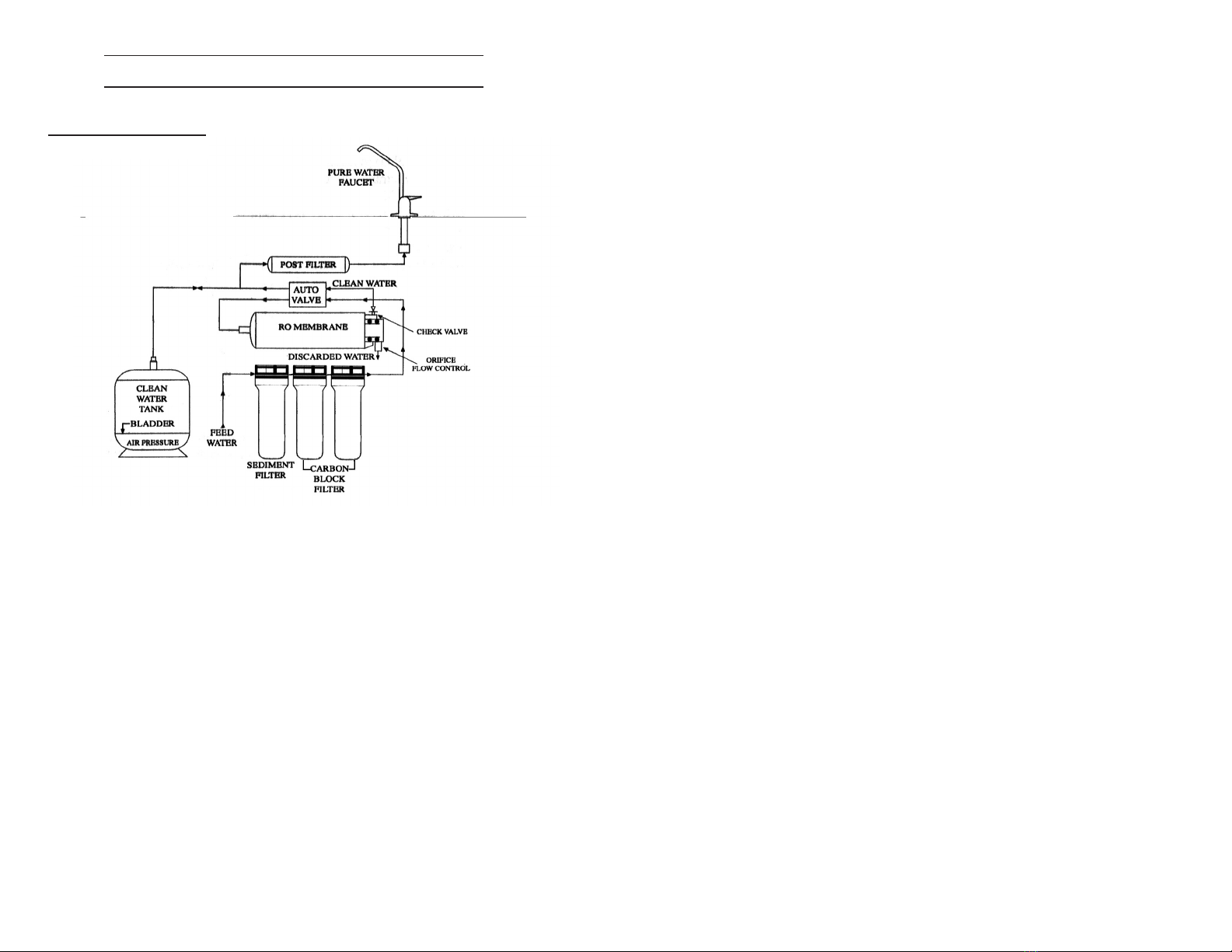
A.1 Pre-Filters
The pre-filters have two purposes, one is to clean the water for better consump-
tion, and the second is to prevent the RO membrane from being polluted. The first
stage filter removes sediment materials such as sand, rust, pipe scale, and dirt. It is
made of a spun polypropylene material that will take out particles down to 5 -
microns.
The water then goes to the carbon block filters, which are important for two rea-
sons. The first takes out 90% of the chlorine in the water thereby protecting the RO
membrane from damage by the presence of chlorine. It also removes the taste of the
chlorine, as well as other tastes and odors that affect the drinking water . (The carbon
accomplishes this by adsorption on its surface). This is a chemical/mechanical
process unique to carbon that has been activated -made to have high surface area. The
second Carbon Block filter is there to also takes out VOCs (volatile organic chemi-
cals) which are contaminants from industrial pollution.
Flow Schematic (Figure A-1)
-15-
A.2 The Reverse Osmosis Membrane
This is the heart of the machine, and the great protector. The membrane is a replica-
tion of human or animal stomach tissue, which permits the water molecule to pass
through, but holds the dissolved molecules back. This occurs naturally by osmotic pres-
sure developed because of the content of dissolved solids. To make this happen with the
RO membrane we reverse the osmotic pressure by applying pressure to the water (revers-
ing the process of generating pressure) to push the water molecules through the mem-
brane, but keeping most of the dissolved solid molecules behind. “Most” means about
70% of nitrates and 99% of copper, lead, and other high molecular weight material.
The reverse osmosis technology will, on average, reject 93% of the total dissolved
solids in the incoming water. Over time, the RO membrane will foul with a very thin
layer of materials and the efficiency will drop, so that the TDS content of the clean water
will rise. When it rises to greater than 30% of the inlet TDS value, it is an indicator that
the RO membrane should be replaced. This occurs every 3-4 years. (See Section 4)
About 4 gallons of water is discarded for every gallon of pure water made. In
Figure A- 1, the discard is shown with a flow control orifice at the outlet of the RO
stage. This is designed to hold back the discard water to the above ratio, and maintain
pressure on the water in the membrane. For a 75-gallon per day membrane, approxi-
mately 668 milliliters per minute of water are discarded. Note there is a check valve
on the clean water outlet from the RO. The purpose is to prevent backflow of water
to the membrane from the tank or faucet or because of autovalve failure. In the aver-
age household, about 3 gallons of drinking water are used a day.
A.3 Auto Control
As water is produced the pressure in the storage tank increases. To stop production
of water when the tank is full, an auto control valve is used in the system, as shown in
Figure A-1. The pressure in the tank is set nominally to be 2/3 of the incoming line
pressure. When this ratio is reached the autovalve will close. Normal U.S. city water
pressure is 60-psi, therefore the tank pressure, when water flow stops, is 40-psi.
The purified water goes to the tank where it is stored at pressure as described
above. The tank has a bladder in it, and on one side is air at 6-psi, initially. The ini-
tial volume of the storage tank is 4.0 gallons. As the water fills the tank, it pushes
against the bladder, and raises the pressure as it takes space in the tank. When the pres-
sure increases to 40-psi, water flow stops. The net amount of water in the tank when
full, less the space taken by the air at 40-psi is approximately 2.5 gallons. When
water is drawn through the clean water faucet on the sink, the water flows through
the final activated carbon post filter, which polishes the water by taking out any stal-
eness which has set in.When water is supplied to the refrigerator, the line should be
therefore taken after the post filter.
When the raw feed water pressure available is 40-psi or less, the RO membrane
will not operate efficiently or produce water at a reasonable rate. To overcome this use
a system with a booster pump which will raise the water pressure in the system to
about 80-psi.
Rev. 8/08
Copyright VERTEX Industrials, Inc. 2008

VERTEX WATER PRODUCTS
Montclair, California, USA
M-EZ1 REV B • 8/08
Copyright 2008 VERTEX Industrials, Inc.
Table of contents
Other Vertex Water Products Water Filtration System manuals
Popular Water Filtration System manuals by other brands

Nordyne
Nordyne E2 Series installation instructions

amiad
amiad Filtomat MG110 Installation, operation and maintenance instructions

Wateranywhere
Wateranywhere AAA-RO50W MANUAL FOR INSTALLATION, OPERATION AND MAINTENANCE

LifeStraw
LifeStraw Steel user manual

Pentair
Pentair EZ-RO 200/2G-BL Installation & operation guide

Tersano
Tersano iClean mini instructions