Innowater SMC50 User manual

Rev.15‐03‐2017
SALT WATER CHLORINATORS
SMC50‐SMC75
USER MANUAL
IMPORTANT:
‐ The unit must imperavely be connected to a protecve earth conductor.
‐ The unit must imperavely be protected by a 30 mA residual current circuit breaker .
‐ Only qualified and authorized personnel should open the electrical cabinet. Risk of electrical
shock or fire hazard. 230VAC.
‐ The unit must imperavely be installed aer the filter and must be the last element the wa‐
ter passes through before returning to the poll.

2 Rev.15‐03‐2017
CONTENTS
1.Securitywarnings……………………………………3
2.Unitdescripon………………………………….4
3.Controlandpowerpanelinstallaon……...5
4.Cellinstallaon………………….……...……………5
Cellhousing
Electrodeassembly
Flowswitch
Celleleads
5.Pumpcommissioning………………………………6
6.Electricalconnecons.…………………………….7
6.Operaon………………………………………………..7
6.1Screenindicaons
6.2ON/OFFswitching
6.3ONstate:producon
7.Displaymessages……………………………………..9
8.Menus…………………………………………………….10
9.Regularmaintenance……………………..……….11
10.Warnings……………………………..……………… 12

Rev.15‐03‐20173
1. SECURITY WARNINGS
Beforeaempngtheinstallaonoranymanipulaonontheunitmakesuretheitisdisconnected
fromthepowermains.
Theunitshouldbeconnectedtoaproperprotecve earth conductor.
Theunitshouldbeprotectedbyanexternal30 mA residual circuit breaker.
Donotoperatethechlorinatorifthepumpisnotrunningoriftheflowthroughthecelliistoolow.
Thegasgeneratedintheelectrolycproceedscouldbreakthecellandeventuallyexplode.
Donotinstallthecellbeforethefilteroranyotherelement.Thecellmustbethelastelementthewa‐
terpassesthroughbeforereturningtothepool.Otherwisethegasgeneratedinthecellcouldbuildup
inthecircuitandcauseanexplosion.
Installtheunitinafreshandwellvenlatedareaandprotectedfromfloodingandliquidsplashes
Onlyqualifiedtechnicalpersonnelshouldmanipulatetheunit.Themanufacturerdeclinesanyrespon‐
sibilityderivedfromtheinstallaon,thestartupandfromanymanipulaonoraddedcomponentnot
factoryinstalled.

4 Rev.15‐03‐2017
TheSMC75isanhighperformanceelectrolycchlorinegenerator.Theunitproducespurechlorine,with‐
outanyaddives,directlyfromwaterwithasaltconcentraonabove4.0gr/l.Thechlorinatorisinstalled
in‐lineinthepoolfiltraoncircuit.Partofthereturnwaterflowisforcedthroughthecellbymeansofaby‐
passplacedattheendofthecircuit,oncethewaterhaspassedthroughthefilterandthroughanyother
elementandjustbeforethereturntothepool.Whenpassingthroughthecell,thewateracquiresahigh
andveryeffecvechlorineconcentraoncapableofdestroyingmostcontaminants.
TheSMC75mainelementsare:
1. Power and control cabinet.Ithousesthecontrolandpowerunits.
2. Control keyboard and display.
3. Cell housing. Itsholdstheelectrolyccellandispoweredbytwocellcablesandconnectors.Two63mm
unionsaresupplied.
4. Electrode assembly.
5. T fing for the flow switch
2 . UNIT DESCRIPTION
1 3
4
2

Rev.15‐03‐20175
3. CONTROL AND POWER PANEL INSTALLATION
Installtheunitinafreshandwellvenlatedplace.Mountthepanelonthewallusingthesupportsonits
back.Thepanelshouldimperavelybemountedupright.
Keep any acid tanks away from the room where the unit has been installed. Acid vapours aack
metals including stainless steal and destroy electronic circuits.
Keep the top of the panel and the heat sink area clear of any objects.
4. CELL INSTALLATION
Cell housing
Thechlorinatormustbefedwithfilteredwater.Installthecellhousingbymeansofaby‐passattheendof
thereturn waterflow:oncethewaterhaspassedthroughthefilterandthroughanyotherelementand
justbeforethereturntothepool.Sendtheflowintothecellbyparallyclosingthemainpipevalveunl
youobtainarapidandsmoothflowthroughthecell.

6 Rev.15‐03‐2017
Inordertoeffecvelyevacuatethegasgenerated,thewateroutletmustalwaysbeabovethewaterinlet.If
thecellisinstalledvercally,thewatermustenterthecellthroughtheboominlet.
Do not install the cell before the filter or any other element. The chlorinator cell must be the last ele‐
ment the water passes through before returning to the pool. Otherwise the gas generated in the cell
could build up in the circuit and cause an explosion.
Electrode assembly
Oncethecellhousingplacementisreadyremovethecellhousingformthepipingbeforeinserngtheelec‐
trodeassembly.Supportthecellhousingagainstitsbase.Donotsupportthecellhousingagainstitsboom
fingbecauseitcouldbreak.VerifythattheOringsealisinitselectrodeassemblyhousingandinsertthe
electrodeassemblyinthecellhousing.Theopenuppersidesoftheelectrodeassemblymustbealignedwith
theupperwateroutletofthecellhousing.Pushtheelectrodeassemblydowntothetopunlthelocking
ringslotinthecellhousingisclear.Installthelockingring.
Whenthecellisbeingfilledwithwater,theairtrappedinthetubecanpreventthewatertoflow.Youcan
temporarilyloosetheflowswitchinordertoevacuatetheairinside.Oncethecelltubesarecompletely
filled,don’tforgettoreghtentheflowswitch.Verifythatthearrowmarkingontheflowswitchcorre‐
spondstothewaterflowdireconaerreghtening.
Watermustflowatsufficientspeedtroughthecell.Iftheflowistoolow,scalecouldbuildontheelectrodes.
Iftheinstallaonisnotprovidedwithadedicatedpumpforthechlorinator,adjusttheflowratebyacng
ontheby‐passcentrevalve.
Flow switch
Install the flow switch preferably downstream. Install the T‐fing horizontally so that, once installed, the
flow switch will stand vercally. If you cannot install the switch vercally make sure the arrow points up
NEVERDOWN.BeforeghtentheflowswitchverifythattheOringisonitshousingandthatthearrow
markingontheswitchbodymatchesthewaterflowdirecon.
Cell cables
Connecteachcellcableconnectoronanythree‐pinrow.Pushtheconnectorsdowntothetop.
5. PUMP COMISSIONING
Verify that the locking cell rings are properly installed before starng the pump. Press the rings out‐
wards along their enre length to make sure they are enrely inserted in the slots .
When water is being injected into the cell, make sure that there aren’t any CLOSED VALVES down‐
stream because the pressure generated will break the cell housing. Similarly, NEVER CLOSE any
valves downstream when the pump is running.

Rev.15‐03‐20177
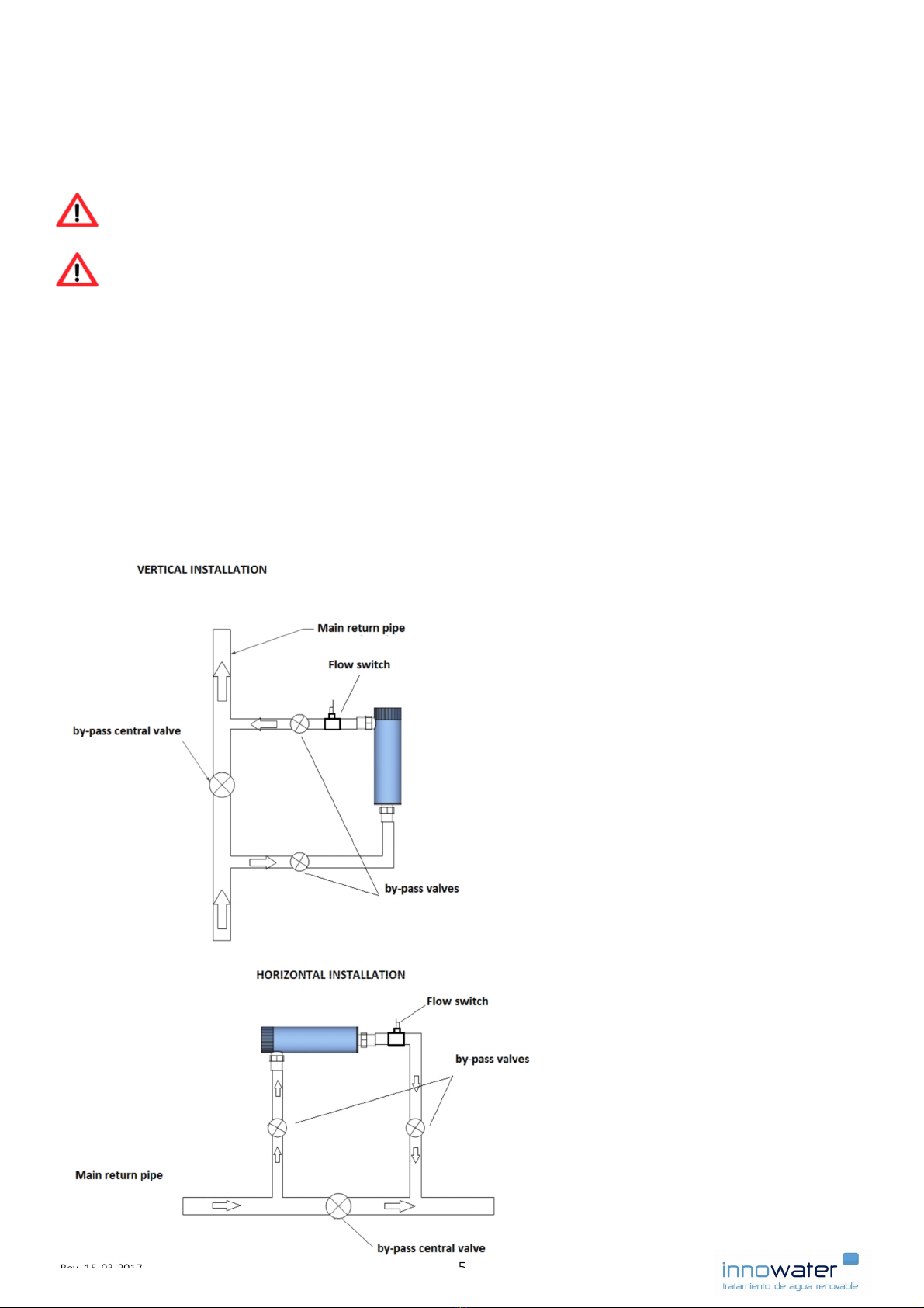
Beforestarngthepumpforthefirstme,openthecentralby‐passvalvefullytoavoidanyoverpressurein
thecellhousing.Oncethepumpisrunning,opentheinletandoutletvalvesslowlyunltheyarefullyopen.
Youcanthenparallyclosethecentralvalveinordertosendtheflowthroughthecellunlyouhavearapid
anuniformflow.Thewatermustflowatasufficientspeedthoughtthecell.Iftheflowistoolowscalecould
buildontheelectrodes.Iftheinstallaonisnotprovidedwithadedicatedpumpforthechlorinator,adjust
theflowratebyacngontheby‐passcentrevalve.
Whenthecellisbeingfilledtheairtrappedinthecellhousingcanpreventthewatertoflow.Youcantem‐
porarilyloosetheflowswitchinordertoevacuatetheairinside.Oncethecellhousingiscompletelyfilled,
don’tforgettoreghtentheflowswitch.Verifythatthearrowmarkingontheflowswitchcorrespondsto
thewaterflowaerreghtening.
6. ELECTRICAL CONNECTIONS
Power supply cable
Thechlorinatormustbepoweredto230VAC.Connectthethree‐wirepowersupplycable(marked“230VAC
powersupply”)toapermanent230VACmainspowersupplywithprotecveearth.Thevoltageonthiscable
mustbekeepconstantaslongasthechlorinatorisinuse.DO NOT INTERRUPT the power on this cable
alongthepumpworkingcyclesorbymeansofanyothercontroldevice.Inordertocontrolthechlorinator
produconcyclesusetheExternal Control Cable.Disconnectthepowersupplyonlywhenyouarenotgoing
tousethechlorinatororincaseoffault.
The chlorinator must imperavely be connected to a protecve earth through its power supply cable
and protected by a 30 mA residual circuit breaker.
External Control Cable
Thetwo‐wirecablemarked“EXTERNAL CONTROL 230VAC”isusedtostartandstopthechlorineproducon
synchronicallywiththepumpworkingcyclesorbymeansofacontroldevice.Whenthevoltageappliedbe‐
tweenthetwowiresis230VACthechlorinatorwillproducechlorine.Whenthevoltagebetweenthewiresis
0VACthechlorinatorwillhaltthechlorineproduconandenterapausemode.Therefore,thevoltageap‐
pliedtothecontrolcablemustbedrivenbythesamemeans,signalordevicethatpowersorcontrolsthe
pump.
Make sure that the voltage applied to the External Control Cable is 230VAC ONLY when the pump is
running and the water flows freely through the cells and to the pool.
6. OPERATION
TheSMC50‐75celliscontrolledbymeansofakeyboardandadisplay.Inaelectrolyccell,chlorinegenera‐
onisproporonaltotheelectricalcurrentflowingthroughit.TheSMC50‐75willtrytomaintainaconstant
electricalcurrentinthecellaccordingtothechlorineproduconrate(0—100%)setbytheuser.Thevalues
ofcurrentandvoltageinthecellareconstantlydisplayedinthemainscreen.Innormalcondionsandat
100%produconratethecurrentvalue(I1)mustbeasfollows:
SMC50:7.0Ato8.5A SMC75:11.0Ato13.5A

8 Rev.15‐03‐2017
6.1 Main Screen Readings
Descripon:
ON → Produconstate
■■■■■■■■■■■■■■■■ 80% → Chlorineproduconseng
I1: 6.4A V1: 23.5V → Cell1workingvalues
I2: —‐ V2: —— → Notusedinthesemodels
Tint 34ºC Wate — → Temperatures Notused
Cext OFF Flow YES → Ext.control FlowSwitch
ON/OFF: indicatesproduconstate.TotogglebetweenONandOFFpresstheMENU (ON/OFF)keyforat
leasttwoseconds.
Producon seng:Indicatesthecurrentchlorineproduconrate.Itcanbeadjustedbypressingthe↑o↓
keys.
I1, V1.: Indicatethecellworkingvaluesandprovideavaluableinformaonforcheckinganddiagnose.At
100%produconrateandinnormalcondionsI1andI2shouldbebetween:
SMC50:7.0Ato8.5A SMC75:11.0Ato13.5A
Tint:Cabinetinteriortemperature.
Water: Watersensorstate(—whennotimplemented).
Cext: Externalcontrolsignal(signalreadbytheExternalControlCable)
Flow: Indicatesthestateoftheflowswitch.
6.2 Switching the unit ON and OFF
ToalternavelyswitchtheunitONandOFF,makesureyouarein the main Screen and press the MENU
(ON/OFF) keyforabouttwoseconds.IfthedisplaywasnotintheMainScreen,youcanalwayscomebackto
itbypressingoneorseveralmestheMENU key.Theunitstate(ONorOFF)isindicatedintheupperlineof
thedisplay.
Whenyouconnectthemainspowersupplyforthefirstme,thedisplaywilllightandtheunitwillremainin
OFF state.Dependingonhowtheunithasbeenprogrammed,wheneverthemainsisdisconnected,theunit
willremaininOFFstateorwillrememberitspreviousstate(ONorOFF)oncethemainspowerhasbeenre‐
stored.
ON
■■■■■■■■■■■■■■■■ 80%
I1: 6.4A V1: 23.5V
I2: —— V2: ——‐
Tint 34ºC Water —
Cext OFF Flow YES
EXT. Control OFF

Rev.15‐03‐20179
To control the chlorine producon according to the pump running cycles or any other signal use the Exter‐
nal Control Cable as explained in secon 5. DO NOT disconnect and reconnect the mains power supply ca‐
ble.
WhentheunitisinOFFstatethechlorineproduconisnotallowedbutyouwillsllhaveaccesstothepro‐
duconsengs,menusandtoallworkingparameters.
6.3 ON state : Chlorine producon
BypressingtheMENU (ON/OFF) keyfortwosecondsthedisplaywillshowONinitsupperlineandthechlo‐
rineproduconwillstart(providedallsignalreadingsareOK:Flow=ON,Cext=ON,etc.).TheI1, V1 values
willincreaseprogressivelyunltheyreachthecellworkingpoint.Youcanadjustthechlorineproduconrate
atanymomentbypressingthe↑o↓keys.Thereisaminimumproduconadjustablerate(normally30%)
topreventthecellfromworkingoutofitsopmalperformancerange.
InONstate,thechlorineproduconisstartedorhaltedaccordingtotheExternalControlCablesignal.The
stateofthissignalisalwaysshownonthescreennexttothe“Cext”label.
‐WhentheExternalControlCablesignalisON(230VACbetweenitswires),),theCext readingturns
ON andthechlorineproduconisstarted.
‐WhentheExternalControlCablesignalisOFF(0VACbetweenitswires),),theCext readingturnsOFF
andthechlorineproduconishaltedunlthesignalturnsonagain.Thispausingstateisalsoindicated
onthescreenboomlinewiththemessageCONTROL EXT. OFF.Beawarethat,eveniftheproducon
ishalted,theunitissllinON state.
7. DISPLAY MESSAGES
Theboomlineofthescreenisusedtoindicatethefollowingstatesorfaults:
CONTROL EXT. OFF
ThismessageisdisplayedwhentheunitisinONstatebutthecontrolsignalisinOFFstate(externalcontrol
cablewiresat0VAC).TheproduconishaltedunlthesignalwillturnbackON.
NO FLOW
TheflowswitchhasdetectedNOFLOW.ThesystemstopstheproduconandturnstheunittoOFFstate.
IftheuserpressOKtoconfirmthemessage,theunitwillstopdisplayingthemessageandwillthenremainin
OFFstateindefinitelyunltheuserturnstheunitONagain(MENU (ON/OFF) + 2 seconds).
IfwaterflowisdetectedagainbeforetheuserhaspressedOK,theunitwillcomebacktoONstateandthe
chlorineproduconwillresume.
CELL NOT DETECTED
ThesystemdoesnotdetecttheacellandturnstheunitOFF.Verifyifthecellisproperlyconnectedorifsalt
hasbeenaddedtothepool.PressOKtoconfirmthemessage.Thesystemwillstopdisplayingthemessage
andtheunitwillgoonOFFstate.Oncetheproblemhasbeensolved,theusercanturntheunitONagain.

10 Rev.15‐03‐2017
LOW SALT
Theesmatedsaltconcentraonislowerthantheopmumworkingrange.TheunitwillremaininONstate
andchlorineproduconwillconnuenormally.Thismessagecanalsobedisplayedifthewateristoocold,
theelectrodesareworn‐outorcalciumhasbuiltupontheelectrodes.
SALT TOO LOW
Theesmatedsaltconcentraontoolowandoutoftheworkingrange.Thesystemwillstoptheproducon
toavoiddamagetothecell.Thismessagecanalsoappearifthecellisnotproperlyconnected.PressOKto
confirmthemessage.ThesystemwillstopdisplayingthemessageandtheunitwillgotoOFFstate.Oncethe
problemhasbeensolved,theusercanturntheunitONagain.
PAUSE 04:54
Whenthesystemiscarryingoutapolarityinversion,theunitentersapausemodeandtheremainingmeis
displayedonthescreen.
8. MENUS
Toenterthemenus,presstheMENUkeyandmoveupordownbetweenthedifferentsub‐menususingthe
↓↑keys.Toenteraparcularsub‐menupressOK.Onceinasub‐menuuse↓o↑tochangeaparameter,
MENUtogotothenextparameterandOKtoconfirmandsavechanges. Then, use MENU once or more
mestocomebacktotheMainScreen.
8.1 Funcons menu
8.1.1 Language
SelectthelanguageandpressOK.
8.1.2. LCD Contrast
Thismenuisnolongerimplemented.Inordertobeabletoadjustthecontrastevenwhenanincorrect
seng does not allow to read the screen, a potenometer marked with “CONTRASTE” has been
mountedonthePCB,inthereversesideofthedisplay.Ifyouneedtoadjustthecontrast,openthe
cabinetdooranduseasmallscrewdrivertoturnitslowlyunlthecontrastisOK.
8.1.3. Readings
Thisisanonly‐readscreenthatprovidesalistofsystemmeasurements.Thesevaluesareusedfordi‐
agnoseintechnicalsupport.
8.1.4. 4‐20 mA Control
Acvateordeacvatesthe4‐20mAexternalcontrol.
8.1.5. pH Adjustment —opon
FollowtheinstruconsjoinedwhenthepHoponhasbeenincluded.
8.2 Status menu
Thisisanonly‐readscreenthatprovidesalistofsystemmeasurements.Thesevaluesareusedfordiagnose
intechnicalsupport.

Rev.15‐03‐2017 11
8.3. Programming menu
Theaccesstothismenurequiresapassword.DO NOT enter this menu or try to change any of its parame‐
ters. Any parameter alteraon will reconfigure the system and lead to a fail of the security systems.
9. REGULAR MAINTENANCE
TheSMC50‐75requiresaminimalmaintenancethatisbasicallyreducedtotheinspeconandcleaningofthe
cellanditsconnecons.Nevertheless,thisminimalmaintenanceisfundamentalforgoodoperaonandper‐
formanceoftheunitandtoavoidfutureexpensivefailures.
9.1 Cell
Inspectthecellfrequently.Theelectrodesbladesshouldbecleanandfreefromanybuilduporobjects.The
watermustflowrapidlyandwithoutanyobstaclethroughthetubularcelltoavoidcalciumbuildup.Ifyou
observehighturbulencenearthewaterinletsoralowflowspeed,increasethewaterspeedthroughthecell
bysendingmoreflowtocelltheby‐pass(closinggthecentralvalve).Ifthewaterhardnessisveryhigh,even
afastflowwon’tpreventthescalefrombuildingup.Ifthisoccurs decreasethepolarity period andmake
surethewaterpHstayscloseto7.0.
Thepolymersealunderthecellcapandtheprotecvesleevesoftheelectroderodsmustbothbeintact.If
anydamageisobserved,sendthecelltothetechnicalserviceforinspeconandrecondioning.
TheelectrodesoftheSMC75cellhavebeenbuildusingthemostadvancedtechniqueinthemarketandwith
averyhighqualitycontrol.Howeverthereareseveralsituaonsthatcanreducetheperformanceandthe
lifespanofanyelectrodeandyoushouldavoidthem:
‐Operaonwithalowwaterlevelorflowinthecell
‐Operaonwithscalebuildupontheelectrodes
‐Frequentacidcleansing
‐WaterpHtoohighortoolow
‐Acidinjeconbeforethecell
9.2 Cell pins
Checkregularlytheconneconareaofthecellandmakesureit’scompletelydryandclean.Turnthe
unitOFFandremovethecellconnectors.Verifythatallthepinsaremoderatelyghten.
Tighten the pins preferably by hand.If you use a wrench, do it very carefully because you could easi‐
ly damage the sealing or the electrodes.

12 Rev.15‐03‐2017
10. WARNINGS
‐ NEVER power the unit without being connected to a protecve earth conductor.
‐ NEVER operate the chlorinator without an external 30 mA residual circuit breaker protecon.
‐NEVERoperate the chlorinator if the pump is not running or if the flow through the cells is too low.
The gas generated in the electrolyc proceeds could break the cell and eventually explode.
‐NEVER install the chlorinator before the filter or any other element. The chlorinator must be the last
element the water passes through before returning to the pool. Otherwise the gas generated in the cell
could build up in the circuit and cause an explosion.
‐ DO NOT access the Programme menu or change any parameter in it.
‐ ALWAYS keep the cell caps, cell terminals, and cell connectors completely dry. Salty water or moisture
will create an electrolyc process and corrode the connectors rapidly..
‐ ALWAYS keep acid tanks away from the unit room.
Other manuals for SMC50
1
This manual suits for next models
1
Table of contents
Other Innowater Water Filtration System manuals
Popular Water Filtration System manuals by other brands

Excalibur Water Systems
Excalibur Water Systems Value Zentec Hybrid Air Capsulate installation manual

Luminor
Luminor RAINIER Operation & installation instructions

Santec
Santec OTF-920 Operation manual

ALCO CONTROLS
ALCO CONTROLS ADKS/FDS Series operating instructions

Brilix
Brilix P350 Installation and user guide

Asutec
Asutec ASMEL-200 operating manual