Vertex PWC-450 User manual

PWC – 450
PureWaterCooler
Copyright 2011 Vertex Water Products
SERVICE MANUAL
for
PureWaterCooler™
by Vertex
Model PWC-450
P/N man-7012

PWC – 450
PureWaterCooler
Copyright 2011 Vertex Water Products
Table of Contents
1. Introduction
2. Cooler Set-up
3. Remove Top Cover/Side Covers
4. Access Cold Tank
5. Remove/Replace Hot Tank
6. Remove/Replace Circuit Board
7. Remove/Replace Dispense Faucet
8. Remove Front Panel
9. Remove/Replace Hot Tank Thermal Sensors
10. Cold Temperature Adjustment
11. Draining Cooler Tanks
12. Remove/Replace Cold Tank Sensor
13. Sanitization Procedure
14. Trouble Shooting
15. Specifications
16. Cooler Exploded View
17. Parts List

PWC – 450
PureWaterCooler
Copyright 2011 Vertex Water Products
PWC-450 Cooler
1. Introduction
The PWC-450 line of point of use counter-top coolers are designed to give years of reliable
Service. The cooler has a single spigot that dispenses water at 2 different temperature
levels – hot and cold temperature water. The main (cold-temp) tank holds 1 gallon of water
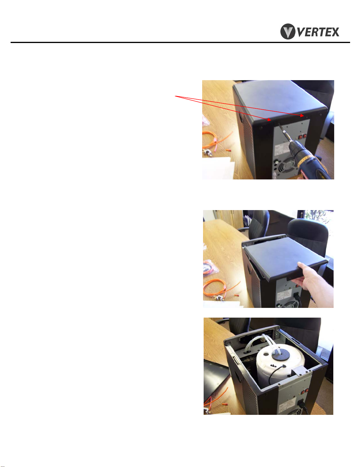
and is constructed of stainless steel. The cold tank can be accessed for cleaning by removing the
cooler main top cover (see section 4).
The hot tank is made of stainless steel and holds 1/2 gallon of hot water. It is important not
to turn on the hot tank when there is no water in it as this will damage the heating element.
The compressor is a sealed unit and is not serviceable in the field. The compressor can be
replaced by a qualified refrigeration technician with proper tools and equipment.
Please consult the factory if the compressor needs servicing.
CAUTION: If the compressor has been stopped by switching it off or unplugging power,
WAIT 10 MINUTES before turning the compressor on again. The compressor may stall
and burnout if powered back on without waiting.
Electrical power is required for the cooler to fill the cooler with water. CAUTION: If hardness
is higher than 7 grains, softening of the feed water is recommended or another option is to
install a “phosphate” filter to the filter system.

PWC – 450
PureWaterCooler
Copyright 2011 Vertex Water Products
Feedwater/Drain Connections
-Feed Connection
2.1 Remove feed water plug (orange) from back
of cooler.
2.2 Connect tubing to feed connector on back of
cooler.
2.3 WARNING: Do not turn on cooler hot power
until cooler tanks are full of water.
2. Cooler Set-Up
(for new cooler installation)

PWC – 450
PureWaterCooler
Copyright 2011 Vertex Water Products
2. Cooler Set-Up cont.
2.4 With both hot and cold power switches in the off
position, plug the cooler into power.
2.5 Press and hold the cold dispense button on the
control panel until water begins to flow from the
spigot. This may take a few minutes depending on
the inlet water pressure. Once the cold tank is full,
repeat this process for the hot tank by pressing the
hot lock button and then holding the hot dispense
button.
2.6 Once both hot and cold buttons dispense water, turn
the hot and cold switches on the back of the cooler
to the on position. Hot water will be ready quickly,
but cold water may take a few hours.
2.7 The cooler is ready for use.

PWC – 450
PureWaterCooler
Copyright 2011 Vertex Water Products
3.1 Remove (2) screws on back of cooler top cover
3.2 Slide cover back and lift off.
3.3 Cold tank is now accessible for cleaning
and servicing other parts of the cooler.
3.4 Reinstall top cover in reverse order
3. Top Cover/Side Panel Removal

PWC – 450
PureWaterCooler
Copyright 2011 Vertex Water Products
3.5 Remove (2) screws on back of cooler side
cover.
3.6 Slide side cover back about half way off
until tab in side cover lines up with slot in
cooler frame.
3.7 Once slot and tab are lined up, pull side
cover away from cooler.
3.8 Reinstall side panels in reverse order
3. Top Cover/Side Panel Removal
Cont.

PWC – 450
PureWaterCooler
Copyright 2011 Vertex Water Products
4. Access Cold Tank
4.1 Remove top and side covers (See section 3)
4.2 Remove tubing (2) from top of cold tank
4.3 Remove tape from top of tank foam (3
plcs). Leave tape attached to lower
foam section.
4.4 Remove top foam of cold tank. Slide cold
temperature sensor vertically out of top
cover while keeping sensor through
foam top.

PWC – 450
PureWaterCooler
Copyright 2011 Vertex Water Products
4. Access Cold Tank
4.5 Place cold temperature sensor and top foam
together off to the side, as shown.
Remove screws from cold tank (8 plcs).
4.6 Using a flathead or similar tool, find the gap
located on the back right side of tank,
and pry the lid from the cold tank with a
twisting motion. Work around the edge
until the lid is loose.
4.7 Remove lid. The cold tank is now accessible.
4.8 Reinstall in reverse order.
cont.

PWC – 450
PureWaterCooler
Copyright 2011 Vertex Water Products
5.1 Drain water from hot tank by removing bottom
drain cap.
5.2 Remove top cover and left side cover (sec. 3)
5.3 Remove (4) electrical connectors from hot tank
temperature sensors.
5.4 Remove (2) electrical connectors from hot tank
heater coil leads.
5. Removing/Replacing Hot Tank.

PWC – 450
PureWaterCooler
Copyright 2011 Vertex Water Products
5. Removing/Replacing Hot Tank
Cont.
5.5 Remove (2) tubes from top of hot tank.
5.6 Remove (2) mounting screws.
5.7 Remove hot tank from cooler.
5.8 Remove inlet tubing.
5.9 Assemble hot tank in reverse order.
5.10 Remove thermal sensors from hot tank. Save and
install on new hot tank.

PWC – 450
PureWaterCooler
Copyright 2011 Vertex Water Products
6.1 Remove dispensing control panel by pulling
outward from the bottom. Once the panel is loose,
remove by pulling down.
6.2 Remove circuit board cover, by removing (2)
screws from the back and pulling the cover off.
6.3 Disconnect (5) electrical connectors from board.
6.4 Remove (2) screws holding circuit board to panel.
6.5 Re-assemble in reverse order
6. Remove/Replace Circuit Board

PWC – 450
PureWaterCooler
Copyright 2011 Vertex Water Products
7.1 Remove top and left side cover of cooler (section 3)
7.2 Remove the control panel, remove the back cover,
and disconnect the electrical connectors. (sec. 6) Set
control panel aside.
7.3 Remove the (2) screws that hold the solenoid
bracket to the cooler.
7.4 Pull bracket out so that all water and electrical
connections to the transformer and solenoids can
be accessed.
7.5 Disconnect power cable from transformer, and
disconnect inlet and outlet tubes so that the bracket
with the transformer and solenoids is free of the
cooler.
7.6 To remove the solenoids and transformer from
the bracket, remove the corresponding screw(s).
7.7 Remove inlet plumbing from solenoids. The inlet
connections can be removed using the same method
for disconnecting tubing from quick connect
fittings.
7.8 Re- assemble in reverse order.
Make note of the following:
a. Water flow through the solenoid is
directional. There is an arrow
molded in the side of the solenoid
body showing water flow direction.
Make sure the solenoid is oriented
correctly. Water can leak from the
solenoid if not installed correctly.
7. Remove/Replace Dispense Solenoid

PWC – 450
PureWaterCooler
Copyright 2011 Vertex Water Products
8. Remove Front Panel
8.1 Remove top and side covers of cooler
(section 3)
8.2 Remove the control panel (section 6)
8.3 Remove (2) screws from the top of the
front panel. The lower part of the front
panel sets on two pins.
8.4 Unscrew spigot nut and remove spigot
from front panel.
8.5 Using pointed tool such as a flathead
screwdriver, push up on the LEDs to
unseat them from the front panel. Then,
using a flathead screwdriver, pry the
LEDs from the front panel.
8.6 Tilt the front panel forward.
8.7 Pass all wiring and the control panel
through the opening in the front panel.
8.8 Lift front panel off of the two pins on
the base. Remove the panel.
8.9 Re-assemble in reverse order.

PWC – 450
PureWaterCooler
Copyright 2011 Vertex Water Products
9. Remove/Replace Thermal Sensor
10.0 The hot tank thermal sensors are located
on the outside of the hot tank. There are
two thermal sensors. The sensor located
lower on the hot tank controls the daily
operation of the heating element. The
upper thermal sensor is an overheat
safety switch and cuts power to the hot
tank should a malfunction occur and
the tank starts to overheat.
10.1 Unplug cooler from power source for
this operation.
10.2 Remove right side cover per sec. 3.3
10.3 There are (2) thermal sensors attached with
screws to the hot tank. The lower sensor auto-
matically turns the heating element on and off
to maintain the water at 180 ºF. The upper
sensor is the over temperature sensor. This
sensor activates if the temperature on the tank
goes over 212 ºF. If this sensor is activated due
to a overheat condition, it will cut the power to
the heating element. If this happens, it will
automatically reset once the temperature decreases.
To check if either thermal sensor is good, use a
continuity tester (ohm meter) to check for
continuity across the thermal sensor. Before testing,
make sure that at least one of the wires is
disconnected from the sensor so as not to test
continuity across a different part of the system.
Make sure the thermal sensor is at ambient
temperature for this test. If there is no continuity,
replace the sensor.
10.4 To change either sensor, disconnect (2)
electrical terminals from sensor.
10.5 Remove (2) screws holding sensor to tank.
10.6 Install new thermal sensor, replace screws,
reconnect electrical terminals to sensor.
10.7 Replace right side cover.

PWC – 450
PureWaterCooler
Copyright 2011 Vertex Water Products
11.0 The cold water temperature adjustment
is located on the back of the cooler in
the middle of the panel. An expansion
tube senses temperature in the cold
tank and open and closes the thermostat.
11.1 The cold adjustment is a shaft with a
screw driver slot on the end.
11.2 To make the water colder, using a
screw driver, rotate the shaft clockwise.
For warmer water rotate the shaft
counter clockwise. There are stops on
the adjustment shaft. DO NOT force
the control shaft over the stop. If this
happens, it will be necessary to replace
the temperature controller
10. Cold Tank Temperature Adjustment
STOP
COLDEST
270º Travel
STOP
WARMEST
Normal Travel is 270º

PWC – 450
PureWaterCooler
Copyright 2011 Vertex Water Products
Completely draining the tanks is required when
shipping the cooler or when one the of the tanks
needs replacing. This procedure will allow you to
remove all the water from the cooler.
11.1 Hot and Cold Tank Drain: Rotate drain caps
until caps are able to be pulled off of the drain
port manifold. Remove drain caps. Water will
pour from the ports.
11.2 Drain any remaining water in the system by
pressing the hot and cold dispense buttons.
11.3 Replace Drain Cap(s).
11. Draining Cooler Tanks

PWC – 450
PureWaterCooler
Copyright 2011 Vertex Water Products
12. Remove/Replace Cold Tank Sensor
12.1 The cold tank sensor is extremely reliable
and rarely needs replacing. Its function
is to control the cold water temperature by
turning the compressor on or off as needed.
11.2 Remove the top cover of the cooler (sec. 3)
11.3 Carefully peel back adhesive foam.
11.4 Slowly pull out the sensor.
11.5 Remove (2) screws on back of cooler that
hold temperature switch to cooler.
11.6 Pull temperature switch out of cooler and
remove (2) electrical connectors.
11.7 The Cold Tank Sensor is now free of the
cooler.
11.8 Re-assemble in reverse order.

PWC – 450
PureWaterCooler
Copyright 2011 Vertex Water Products
The sanitization procedure is performed to reduce/eliminate any bacteriological
growth in the cooler tanks and dispensing plumbing. Bacteriological growth
can be the cause of some taste and odor in the water.
The procedure is as follows:
1. Mix ½ Tsp. of common household bleach (5.25%) in 1 gallon of clean
water into a filter housing fixed with ¼” ports.
2. Unplug the cooler from the power source.
3. Drain all water from the cooler tanks.
4. Plumb the filter housing into the inlet water to the cooler.
5. Simultaneously press the hot and cold dispense buttons on the control panel.
6. When the mixture begins to flow from the spigot, release the hot dispense
button.
7. When the mixture begins to flow from the spigot again, release the cold
dispense button.
8. Let the sanitizing solution stand in the cooler for 10 minutes.
CAUTION: Leaving the sanitizing solution in the cooler for more
than 10 minutes can cause taste problems in the water.
9. While solution stands, disconnect the filter housing from the water line.
10. Drain the cooler completely.
11. Re-plumb fresh tap water to the cooler.
12. Fill the cooler completely with water. Let a few pints of water drain out of
the spigot while pressing the hot button and then the cold button.
13. Drain the cooler completely.
14. Repeat steps 12-13, 2-3 times.
15. The cooler is now sanitized and ready for normal use.
13. Sanitization Procedure

PWC – 450
PureWaterCooler
Copyright 2011 Vertex Water Products
14. Trouble Shooting
(Water dispenses from spigot but is not cold)
Possible causes Solution .
1. Power switch not on Make sure cold power switch on
the back panel is on.
2. Adjust temperature control The thermostat temperature control
adjustment is located on the back
of the cooler. (see section 9)
3. All cold water has been used Cooler needs time to recover.
wait 10-15 minutes until water cools
Water not cold from cold tank
Table of contents
Other Vertex Water Dispenser manuals

Vertex
Vertex PureWaterCooler PWC-3500 Quick start guide

Vertex
Vertex PureWaterCooler PWC-1800 User manual

Vertex
Vertex PureWaterCooler PWC-400 F Quick start guide

Vertex
Vertex PureWaterCooler PWC-8000 Quick start guide

Vertex
Vertex PWC-450 F User manual

Vertex
Vertex PWC600 User manual

Vertex
Vertex PureWaterCooler PWC-400 User manual

Vertex
Vertex PWC-500 User manual

Vertex
Vertex PWC-7000 User manual

Vertex
Vertex PWC3000 Quick start guide