Vertical Doors Simply Uplifting Lambo Instruction manual

Page 1 of 12 GENERAL INSTRUCTIONS
Installation
KHJKK
CHEVROLET CAMARO 2010
U.S. PATENTS
#6,808,223; #6,845,547; #7,140,075; #7,059,655
PATENTS AGGRESSIVELY ENFORCED!

Page 2 of 12 GENERAL INSTRUCTIONS
Installation
PICTURE ABOVE IS THE UNIVERSAL KIT; YOUR KIT MAY BE
DIFFERENT.
THIS KIT INCLUDES:
8 M8-1.25X30MM BOLTS
WITH WASHERS RIGHT AND LEFT HINGE
ASSEMBLY
8 M8-1.25X40MM BOLTS
WITH WASHERS 2 SHOCKS 640 PSI
2 PINS 2 SHOULDER BOLTS WITH
WASHERS
TOOLS REQUIRED FOR INSTALLATION:
AIR RACHET, GRINDER AND
CUTTER.
7MM, 8MM,10MM, 11MM,
13MM, SOCKETS AND
EXTENSION.
FORK AND PHILLIP’S SCREW
DRIVERS
SPACERS FOR THE DOOR
GAP.
3/16 ALLEN WRENCH
1/4 TORX BIT
9/16 WRENCH
LOCKTITE RED

Page 3 of 12 GENERAL INSTRUCTIONS
Installation
OTHER TOOLS MAY BE NEEDED DEPENDING ON YOUR VEHICLE.
“Installers with experience recommended”
(Note: The pictures on the manual are for reference only
they may not match your vehicle.)
1) Disconnect the battery.
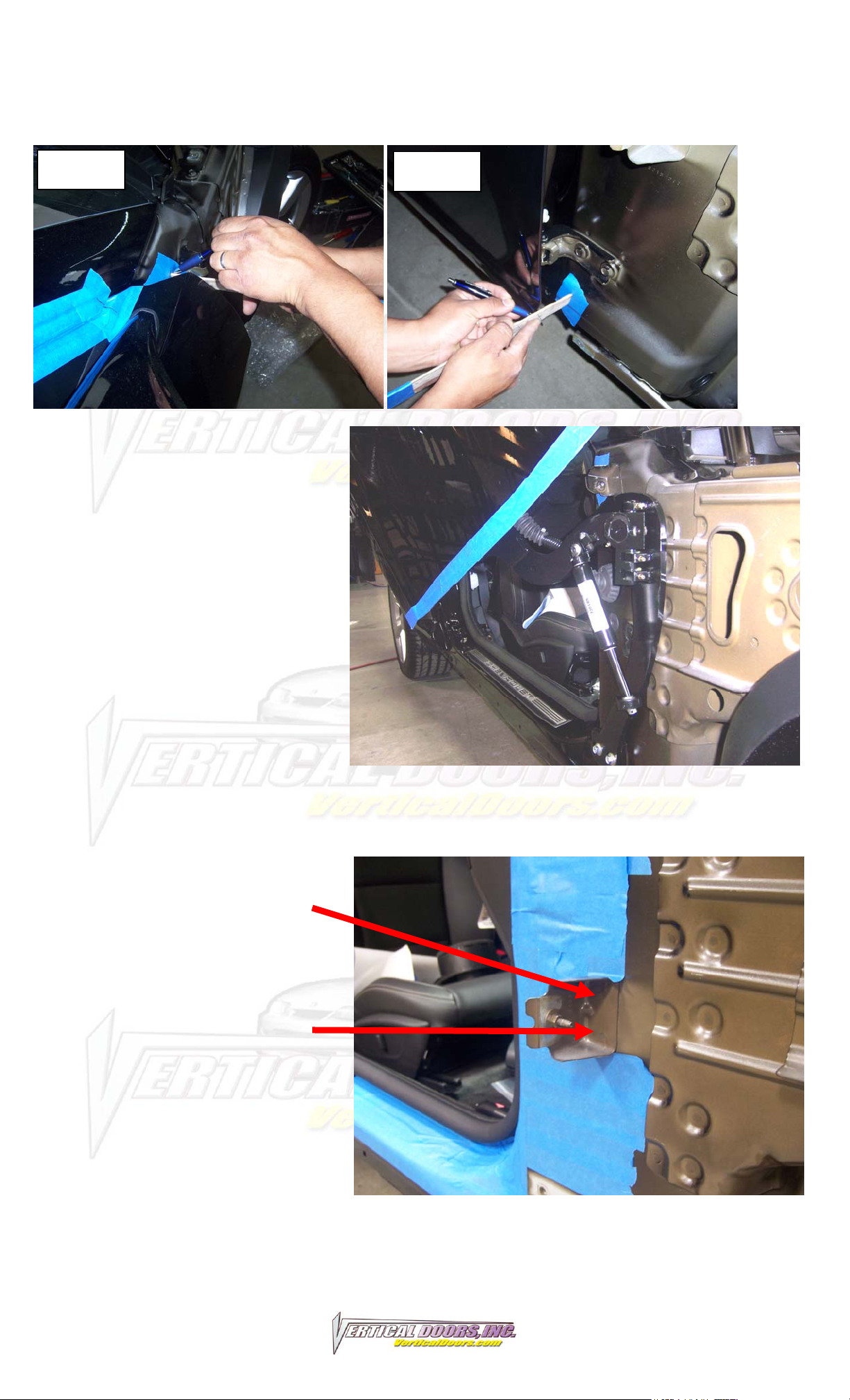
2) Remove fender:
Remove all Phillip’s
screws or fasteners from
the wheel well.
Pull the front bumper
forward to gain access to
the bolts hold the front
section of the fender the
chassis.
Open the door and
remove the bolts holding
the back of the fender to
the chassis.
Also remove the bolts
securing the doors catch.
Note: you will need to
remove the door panel to
remove the door catch.
Make sure to replace the
door panel after removing
the door catch.
Close the door and
remove the side skit to gain access to 2 bolts securing the fender to
the bottom of the chassis.
Finally remove the top bolts on the top of the fender this will allow
you to carefully remove the fender.

Page 4 of 12 GENERAL INSTRUCTIONS
Installation
3) You will need more wire slack:
Remove foot trim, and
kick plate under it you will
find a wire harness.
On the driver side undue
the clips holding the wires
to the body as shown and
re-route wire from its
original location on the
left the to the right as
shown on the picture this
will allow you pull the
extra wire slack needed
to raise the doors.
On the passenger’s side
the wire re-routing will be
similar to the Driver’s
side.
4) Place tape around the
door and body of the
vehicle as shown to help
you locate the factory
location. Then use 2”
painters tape to secure
the door to the body.
Note: note the most
important part of the
installation is marking the
factory location of the
door.

Page 5 of 12 GENERAL INSTRUCTIONS
Installation
Make sure to mark how far the edge of the door is from the boy as
shown in “PIC 1” top and “PIC 2” bottom.
5) After making sure you
have all the marks you
need in case the door
moves during installation,
you can remove the
factory door hinges. After
installing the new VDI kit
you should be able to
raise the doors and start
the fine tuning you’re
your new VDI kit.
Note: wire loom will have
to be cut in half, use provided wire loom to protect the exposed
wires.
You will have to remove
one of the fender
brackets. To remove it
undue the 2 weld spots
this will allow a clean
removal of the bracket.
PIC 1 PIC 2

Page 6 of 12 GENERAL INSTRUCTIONS
Installation

Page 7 of 12 GENERAL INSTRUCTIONS
Installation
2
3
1
6) Once hinge is locked in place, break nut #1 then turn Allen set
screw #2 on fig until it hits the block then open the door and
continue to adjust until the door matches with the striker, open and
close door making sure it closes like factory.
Hint*(leave #1 nut loose until shock is installed Allen set screw will
have to be re-adjusted after shock is installed.
7) Install the shock.
Hint* (You will need a helper to raise the door). (Slip the spherical
rod mount into the spherical ball bearing (1). Using a 1/4 Allen
wrench, tighten the screw into the swing arm (2). After the shock is
installed secure it by installing the pin in the bottom shock end (3).
SCREW #2
NUT #1
BODY OF
CAR DOOR

Page 8 of 12 GENERAL INSTRUCTIONS
Installation
8) After shock is installed re-install door panel and lift the door.
Adjust door opening screw #3 clockwise until distance between nub
and swing arm is enough so that the swing arm moves up and
down freely.
Hint* (Fine tune the Allen Adjustment screw (#2) to realigned striker
with door. After the door is align test door by opening and closing,
lifting and lowering door several times.
Note: Do not install fender until the adjustment of the door is
accurate, and the set screw is tightly secure. Also make sure
everything is tight, adjustment is set and everything is
Locktite.
ADD GREASE TO ZERK FITTINGS

Page 9 of 12 GENERAL INSTRUCTIONS
Installation
9) Modify factory wire loom:
In order to be able to open and raise the door, cut the factory wire
boot in half and add wire loom to protect exposed wires as shown
note the routing of the wires.
10) Cut the inner lip of your fender to make room for the new
Vertical Doors hinge. Note: After you have cut the fender use a
sander or grinder and make sure the surface is completely flat. Cut
the fender along the inside mark of the tape.

Page 10 of 12 GENERAL INSTRUCTIONS
Installation
11) Close the door and replace the fender by reversing step 2.
Hint*(Make sure the electrical wires don’t get pinched enough to
damage wires)
12) For the other side just follow steps 2-11.

Page 11 of 12 GENERAL INSTRUCTIONS
Installation
Popular Automobile Accessories manuals by other brands

Oris
Oris 049943 Fitting instructions

Prorack
Prorack 567 Fitting instructions

travall
travall TDG 1496 Fitting instructions

Star Headlight & Lantern
Star Headlight & Lantern OMEGA 9018LED quick start guide

Toyota
Toyota PC170-0K01A installation manual

Kuda-Phonebase
Kuda-Phonebase 010005 Installation instruction