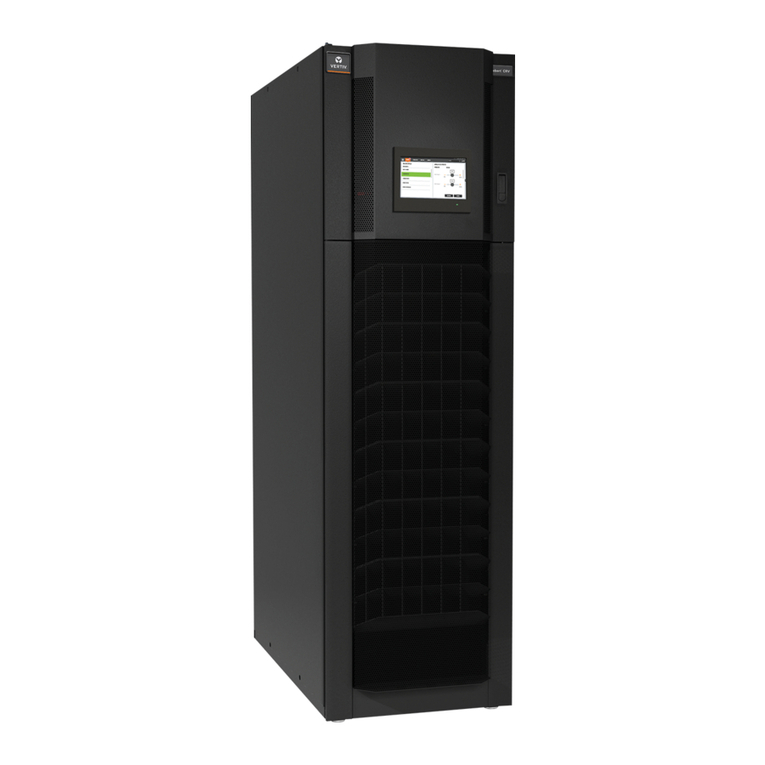
Vertiv Liebert PDX User manual

Liebert®PDX
80-165 kW Indoor Room Cooling Units
with Modulating Capacity
Econophase Version - 50 Hz
User Manual
English, Cod. 265133, rev. 29.08.2019
Use only with:
● Liebert®MC, EconoPhase Version
● Liebert®EconoPhase, Pumped Refrigerant Module

Liebert®PDX, EconoPhase Version - UM - 265133 - 29.08.2019

Liebert®PDX, EconoPhase Version - UM - 265133 - 29.08.2019
IMPORTANT SAFETY INSTRUCTIONS
SAVE THESE INSTRUCTIONS
This document, written in English, is the original version.
Conventions
DANGER indicates a hazardous situation which, if not avoided, will result in death or serious injury.
WARNING indicates a hazardous situation that, if not avoided, could result in death or serious injury.
CAUTION indicates a hazardous situation that, if not avoided, may result in minor or moderate injury.
NOTICE indicates a property damage message.
WARNING
This unit operates and restarts automatically.
If the electrical connection is live, there are residual risks: electric shock, burns, moving parts, automatic
restarting from the remote control.
• Before any operation that requires opening of the door or the equipment panels (maintenance,
cleaning, etc.), disconnect the unit from the power supply.
The ON/OFF switch on the control panel does not isolate the power from the unit, even in the “unit o”
mode. To cut o the power supply, open the insulation device (main switch) which is positioned on the
electrical panel cover, behind the door on the left:
WARNING
This manual was prepared to enable the end user to carry out only the operation that can be done with
the panels closed.
Only qualied personnel are allowed to carry out operations that require opening of the door or the
equipment panels. The panel key supplied with the unit must be kept by a person responsible for the
maintenance.
CAUTION
Before proceeding with installation, read all instructions, verify that all parts are included and check the
nameplate to make sure the voltage matches available utility power.
For identication of the unit (model and serial no.) in case of the necessity for assistance or spare parts,
locate the identication label on the outside of the unit.
NOTICE
The manual is retained for the entire service life of the machine;
The user reads the manual carefully before carrying out any operations on the machine;
The unit control must be used exclusively for the purpose which it is intended for; the manufacturer
takes no liabil ity in case of an incorrect use or a modication of the unit control
MAIN SWITCH
Unscrew the door and open it to access the main switch.
• After opening the door pay attention to the cable and components still energized.
• Open the main switch to cut o the power before removing any protective cover.

Liebert®PDX, EconoPhase Version - UM - 265133 - 29.08.2019
WARNING
The supply cable of the main switch contains live high-voltage.
• The manufacturer highly recommends that the nal customer installs on site an external main switch,
easy to reach and to facilitate a quick and easy shutdown enabling the power of the unit to be cut o.
Refer to the unit electrical schematics for the installation. Follow all local codes.
CAUTION
If the unit door is open while the fans are operating, the airow may suddenly slam the door closed.
There is a risk of being hit by the door and hands being crushed.
• Before opening the door, switch o the unit using the local or remote control panel or the external
main switch (if installed).
If small objects are left loose in the fans bay after any maintenance operation, it may result in the object
ejection at the fans start-up.
There is a risk of being hit by small objects.
• Install all protection panels or a grid before starting up the fans after any maintenance operation.
Position the oor panels also below the unit with the fans below the oor.
WARNING
If the internal compartments are open immediately after the machine has been switched o, there might
be some hazards related to:
• Components still at high temperature: electrical heaters, humidier and steam distributor, hot water
piping.
• Rotating elements (fan impellers, they might continue to rotate for a while by inertia)
• Sharp edges, splinters and exposed fasteners
Pay attention to the warning labels on the unit.

Liebert®PDX, EconoPhase Version - UM - 265133 - 29.08.2019
Attention: data relevant to the unit supplied is indicated
on the inboard label (see the blank facsimile below).
Data in the manual is referred to standard conditions
and can be modied without any advance notice.
POS. DESCRIPTION
1 Compressor Full Load Ampere [A]
2 Compressor Locked Rotor Ampere [A]
3 Compressor quantity
4 Evaporator fan Full Load Ampere [A]
5 Evaporator fan Locked Rotor Ampere [A]
6 Evaporator fan quantity
7 Condenser fan Full Load Ampere [A]
8 Condenser fan Locked Rotor Ampere [A]
9 Condenser fan quantity
10 Electrical heating Ampere
11 Electrical heating steps
12 Humidier Ampere
13 Steam production capacity
14 Max. unit AC Ampere
15 Max. unit DC Ampere
16 Rated peak withstand current
17 Rated short-time current
18 Refrigerant type
19 High pressure switch Stop
20 High pressure switch Restart
21 Low pressure switch Stop
22 Low pressure switch Restart
23 Min. room operation temperature
24 Max. room operation temperature
25 Min. room operation humidity
26 Max. room operation humidity
27 Max. refrigeration circuit pressure
28 Manufacturing plant
29 Manufacturing date
30 Model
31 Serial number
32 Power input
12 3
45 6
78 9
10 11
12 13
14
15
16
17
18
19 20
21 22
23
24
25
26
27
32
30
28
31
29
12
4
7
10
12
14
18
19
21
23
25
27
3
5 6
89
11
15
13
16
17
20
22
24
26
29
28
30
32
31

Liebert®PDX, EconoPhase Version - UM - 265133 - 29.08.2019
Digit 8 - Airow
L= Premium Fan Module
Digit 9 - Main Power Supply
3= Single 400V / 3ph / 50 Hz + N
Digit 10 - Cooling System
X= Dual Circuit Digital Scroll R410A with EEV
Digit 11 - Humidication
0= None
H = Infrared Humidier
U = Ultra Sonic Humidier
S = Electrode Humidier
Digit 12 - Microprocessor Control
2= Inner Display only T sensor
3= Inner Display TH sensor
U = Small Cold re display T sensor
B = Small Cold re display TH sensor
C = Large Cold re display T sensor
D = Large Cold re display TH sensor
Digit 13 - Heating & Re- Heating
0= None
1= Electric heating Std Capacity
2= Electric heating High Capacity
Digit 14 - Air Filter Eciency
1 = F5 (EU5) dust spot
3 = F5 (EU5) dust spot + Clogged Filter
Digit 15 - Condensing Control
1= Air Cooled or Water cooled with Standard Pressure, 2 way MBV
Digit 16 - Colour
1= Black Vertiv RAL 7021
Digit 17 - High Voltage Option
T= Dual Power Supply parallel + Magnetic circuit breaker for 10A
three phases
U= Dual Power Supply Alternate with ATS + Magnetic circuit
breaker for 10A three phases
Digit 18 - Package Option
H= Predisposition for damper
L= Predisposition for plenum installation
Digit 19 - Monitoring
N= No IS Housing
0= No Card
C= Sitescan Monitoring through INTELLISLOT IS-485EXI
P= MODBUS, BACnet, SNMP, Web through IS-UNITY card
Digit 20 - Sensors
0= None
Digit 21 - Packaging
P= PLP And Pallet
C= PLP and Wooden Crate
S= Seaworthy
Digit 22 - Special Requirements
A= Standard Vertiv
X= Special Vertiv
Model Nomenclature / Digit Numbers
18 9 10 11 12 13 14 15 16 17 18 19 20 21 22
65432
PX
Digit 6
Air Discharge
D Downow Up
E Downow Down
Digit 7
System Type
PAir Cooled + predisposition for
pumped refrigerant economizer
Digit 1 and 2
PX Liebert®PDX
7
Digit 3, 4 and 5
Unit Model

1
Liebert®PDX, EconoPhase Version - UM - 265133 - 29.08.2019
1 - Liebert®PDX EconoPhase
System description
1.1 - Liebert®PDX EconoPhase System
Liebert®PDX EconoPhase System is designed to provide
precision air conditioning to computer racks in a data center or
computer room as eciently and eectively as possible.
A Liebert®PDX EconoPhase System is composed of:
• Liebert®PDX EconoPhase version - High Eciency, Digital
Scroll, oor-mounted indoor unit
• Liebert®MC™ Condenser EconoPhase version - Air-cooled
microchannel condenser, premium version
• Liebert®PDX EconoPhase - Liebert®PDX EconoPhase
pump refrigerant module
The Liebert®PDX EconoPhase is an add-on module for use with an
air-cooled Liebert®PDX system. The Liebert®PDX EconoPhase
will allow the system to switch to Liebert®PDX EconoPhase
operation when the outdoor temperature is low enough to provide
the required temperature dierence between the inside air and the
outside air, providing signicant energy savings because there is
no need to operate the compressor. At lower temperatures, the
system switches one or both circuits from Compressor Mode to
Pump Mode. The pump consumes roughly 1/10th of the power
consumed by the compressor.
The Liebert®PDX EconoPhase system maintains this energy
eciency by employing the heat absorption properties of a liquid
(pumped refrigerant) through a phase change. Refrigerant is
pumped as a liquid, becomes a gas within the Liebert®PDX
evaporator and then is returned to the Liebert®MC where it
condenses to a liquid. The subcooled liquid refrigerant from the
condenser is then run directly into the Liebert®PDX EconoPhase
pumps and is circulated back to the Liebert® PDX unit (see Figure
1). The system will operate as a typical air-cooled direct expansion
system when outdoor ambient conditions are unfavorable
to EconoPhase operation. The pumps in the Liebert®PDX
EconoPhase pump module are turned o and bypassed during
compressor operation.
Condenser (Pump Mode)
Condenser (DX Mode)
Indoor Unit
ropaVxiMropaV/diuqiL
Liquid
Pressure
Enthalpy
Tradtional Vapor Compression Cycle
EconoPhase Cycle
Fig.1 - Pressure enthalpy diagram, pumped refrigerant Liebert®EconoPhase

2Liebert®PDX, EconoPhase Version - UM - 265133 - 29.08.2019
1.2 - Liebert®PDX EconoPhase version
The Liebert®PDX is a full- featured precision air conditioner
intended for data centers, network closets, technological
rooms (laboratories, metrological rooms, museums), new and
existing constructions, raised and non- raised oors, moderate
to high density heat loads, also in combination with cold aisle
containments (up to 10 kW/Rack). It provides all the necessary
functions of a standard precision air conditioner, including
cooling, heating, humidication, dehumidication, air ltration,
condensate management, temperature control, alarm functions
and data communications. Thanks to Copeland’s Digital Scroll and
electronic expansion valve availability, Liebert®PDX can achieve
a continuous spectrum of capacity output, ensuring a very tight and
precise control on room temperature. Liebert®PDX can rapidly
change from one capacity duty to another. Therefore it controls
environmental parameters even working with swiftly changing heat
loads. In Digital Scroll Cooling system depending on the unit size
the modulating capacity range is between 15% and 100% of the
nominal capacity. The compressor can drop down to 10%, but the
system will decrease in eciency.
Thanks to the capacity modulation we can reduce the starting
and stopping of the compressor which uses a lot of power and
puts a great amount of stress on the components; therefore we
can enhance eciency and life of the system. With the Liebert®
PDX range we are able to manage unexpected very high ambient
temperatures, maintaining the system active, reducing HP alarm
and troublesome stops of the unit. In fact, when the discharge
pressure reaches the limit value, the compressor capacity is limited
to a fraction of the actual request, in this way restricting the heat
rejection and allowing the system running without interruptions.
If, after a dened time, the condensing pressure comes back
within the limit, the capacity will be modulated in the usual way.
Reliability of the Liebert®PDX is also maximized, thanks to the
fewer system parts and simple electronic controls which reduces
the unit maintenance.
Digital Scroll motor runs at a constant speed throughout the
operating range.
This unique feature increases the applicability of the Liebert®
PDX units into technological rooms, as it eliminates the need
for expensive electromagnetic suppression electronics require
to ensure electromagnetic compatibility. The Digital function
maintains the maximum refrigerant velocity through the pipes. As a
result of these reasons, Liebert®PDX units do not need oil return
components. Liebert®PDX is designed on modular concept.
The Liebert®PDX is supplied as a single unit (height 1970 mm),
where coil and fan sections are connected. The units are available
Downow Up
Downow Down

3
Liebert®PDX, EconoPhase Version - UM - 265133 - 29.08.2019
1.3 - Liebert MC™ EconoPhase Version
The Liebert®MC air-cooled microchannel condenser is a low-
prole, direct-drive propeller fan-type air-cooled unit suitable for
mounting outdoors. It provides heat rejection for either one or two
separate refrigeration circuits, matches the heat rejection capacity
corresponding with the outdoor ambient temperature and with each
corresponding compressor heat rejection requirements.
Constructed with an aluminum cabinet, galvanized steel frame
and microchannel coil, the unit is quiet and corrosion resistant.
The condenser is quickly and easily installed because all internal
wiring is completed at the factory with only electrical connections
and communications connections to be made at the job site. All
electrical connections and controls are enclosed in an integral
weatherproof section of the condenser.
The Liebert®EconoPhase pumped refrigerant system will always
use the premium version condenser.
In EconoPhase operation, the premium control board uses
inputs from the indoor unit, condenser refrigerant temperatures
and ambient temperatures to modulate the EC fan motor speed
from 0 to 100% RPM, maintaining the refrigerant temperature
setpoint. The control system provides temperature control for
outdoor ambient as low as -35°C in pumped refrigerant Liebert®
EconoPhase operation.
1.4 - Liebert®EconoPhase Pump Refrigerant Module
The Liebert®EconoPhase is an option for a Liebert®PDX
EconoPhase Version air-cooled system. The Liebert®EconoPhase
allows an air-cooled direct expansion system to switch from vapor
compression operation to pumped refrigerant operation when
the outdoor temperature is low enough to provide the required
temperature dierence between the inside air and the outside air.
Fig. 2 - Liebert EconoPhase module
1.5 Standard Air-Cooled System vs. Liebert®PDX
EconoPhase System
There are dierences between the standard air-cooled system and
a system designed with the Liebert®EconoPhase. The user must
be aware of these dierences to achieve the best operation. This
section summarizes the dierences; more detailed explanations
are found throughout this manual and the manual of Liebert®
EconoPhase Pump Refrigerant Module.
• Liebert EconoPhase Operation - Liebert®EconoPhase
operation is possible when the outdoor temperature is low
enough to provide the required temperature dierence
between the indoor air and the outside air. This mode turns the
compressors O and turns the Liebert®EconoPhase pumps
On.
• Refrigerant Pumping - During Liebert®EconoPhase
operation, the refrigerant is pumped around the air-cooled
loop instead of going through the vapor compression cycle.
System pressures will vary signicantly depending on whether
the system is operating in standard aircooled mode or in
Liebert®EconoPhase operation.
• Energy Savings - The coecient of performance of the
system increases signicantly during the EconoPhase
operation which results in signicant energy savings for the
user.
• EEV - The system uses an electronic expansion valve during
both direct expansion and EconoPhase operation. The EEV
results in energy savings and helps the pump maintain proper
dierential during EconoPhase operation.
• Piping - The condenser piping is larger than what is typically
specied for Liebert®air-cooled Precision Cooling systems.
The pipe sizing still allows oil return to the compressor
and also allows for ecient operation in both modes of
operation. All eld piped lines must be insulated because the
uid temperatures can be well below the dew point during
EconoPhase operation. All outdoor insulation must be UV
rated and rated for outdoor use.
• Unit/Module Communications - A CANbus connection links
the Liebert PDX and the air-cooled condenser to achieve the
most ecient operation as well as the condenser and the
Liebert®EconoPhase module.
1.6 - Operating Modes
Each circuit on a system combining a Liebert®EconoPhase,
Liebert DSE and Liebert MC has six distinct operating modes:
• Idling with compressor and pumps O
• Startup
• Compressor operation
• Compressor-to-pump changeover
• Pump operation
• Pump-to-compressor changeover
A circuit will run most of the time in either compressor or pump
operation mode. These modes both eciently remove heat from
the conditioned space and reject it via the air-cooled condenser.
The ow paths during each mode of operation are detailed in
Figures 3 and 4.
A couple of dierences to note between Compressor Mode and
Liebert®EconoPhase operation:
• The unit does not dehumidify in Liebert®EconoPhase operation.
If dehumidication is desired, Liebert®EconoPhase operation
must be disabled.
• Bubbles may be seen in the site glass in the indoor unit when
the system is in Liebert®EconoPhase operation. This does not
necessarily mean the system is low on charge.

4Liebert®PDX, EconoPhase Version - UM - 265133 - 29.08.2019
Fig.3 - Compressorized operation ow path
Fig.4 - Pump operation ow path
Check Valve
Check Valve
Check
Valve
Compressor
Condenser
Evaporator
Electronic
Expansion
Valve
Solenoid ValvePump
Check Valve
Condenser
Compressor
Check
Valve
Solenoid
Valve
Electronic
Expansion
Valve
Evaporator
Check Valve
Pump

5
Liebert®PDX, EconoPhase Version - UM - 265133 - 29.08.2019
1.7 - Module Communications
The Liebert® PDX (room unit), Liebert MC™ (microchannel
condenser) and Liebert®EconoPhase (Pumped Refrigerant
Economizer) require communication when combined into a system.
This is done through a CANbus communication interface. A CANbus
cable must be connected from the Liebert®PDX at the designated
terminal(s) to TB49 on the Liebert®MC condenser board. If there is
an additional condenser, TB50 of the rst condenser will continue
out to TB49 on the second condenser.
In a system equipped with a Liebert®EconoPhase, the CANbus
cable must be connected from TB50 on the last condenser to TB49
on the Liebert®EconoPhase CANbus terminal block.
The two devices that are connected at the ends of the CANbus will
require termination to be set by jumper or plug. One end will be at
the last outdoor device in the connection chain; the other end of the
CANbus is either in the indoor unit or at a remote sensor. To
terminate, place a jumper on J6 Pins 1 and 2 on the Liebert®MC
condenser or Liebert®EconoPhase board. For other Liebert®
iCOM boards directly associated with the indoor unit, terminate by
placing a jumper on P78 Pins 2 and 3.
See Fig. 5 for CANbus connections, jumper and DIP switch settings.
• Length Restrictions
• The indoor Liebert®PDX can be no more than 100m
from the condenser. The CAN communication cable can
be longer, but the total length should not exceed 150m
between the indoor Liebert®PDX unit and all outdoor
equipment.
• Cable Type
• Conductors-22-18AWG stranded, tinned copper
• Twisted pair (one pair is required for connection)
• Braided shield or foil shield with drain wire
• Low capacitance (<=15pF/ft)
• Cat5e or similar
• UL approved temperature rated to 75°C (167°F)
• UL approved voltage rated to 300V
• UV - and moisture - resistant if not run in conduit
• Plenum rated-NEC type CMP, if required by national or
local codes
• High Voltage Restrictions
• Do not run communications cable with high voltage cable.
• When routing cable, avoid laying, fastening or coiling
near or on high voltage wiring, conduit, or light ballasts.
Communication signals in equipment may be disturbed.
• Keep communications cable away from other electrical
noise sources.
• Environmental and Safety
• Vertiv®recommends routing cable inside conduit where
the cable exits the building to outdoor units, between
outdoor units and any other location where environmental
conditions could degrade the cable’s integrity.
• Follow all national and local codes regarding cable
routing, ratings, etc.
Fig.5 - CANbus connections
P67
Indoor Unit With
Liebert iCOM
Factory-Installed CANbus Cable
Field-Installed CANbus Cable
J6
1
3
J6
1
3
J6
1
3
J6
1
3
12345678
CAN
On
12345678
CAN
On
12345678
CAN
On
12345678
CAN
On
TB50
TB49
Liebert
EconoPhase
Circuit 1
TB50
Liebert
EconoPhase
Circuit 2
TB50
Liebert
MC Unit
Circuit 2
TB50
TB49
Liebert
EconoPhase
CANbus Terminal Block
TB49
TB49
TB50
TB49
Liebert
MC Unit
Circuit 1
Connect wire 3 to PIN1and wire 4 to PIN3

6Liebert®PDX, EconoPhase Version - UM - 265133 - 29.08.2019
1.8 - Description of Liebert®EconoPhase Operation
The Liebert®EconoPhase unit enables the Liebert®PDX system
to operate in any of three modes to control temperature, depending
on the outdoor temperature and the load.
• Compressor Mode
• Pump Mode
• Mixed Mode
When the outdoor temperature becomes low enough to provide
the required temperature dierence between the inside air and
the outside air, there is no need to compress the refrigerant to a
higher pressure/temperature. When the outdoor temperature is
low enough, the system switches from Compressor Mode to Pump
Mode or to Mixed Mode.
• Compressor Mode: All available compressors may be used
to maintain the control temperature. All the available Liebert®
EconoPhase pumps are O. The control will typically run in
this mode when the load and temperatures are such that full
or partial Liebert®EconoPhase operation is not possible, or
because certain pumps have experienced alarms.
• Pump Mode: All of the available pumps may be used to
maintain the Control Temperature. All the compressors in the
system are O. The control will typically run in this mode when
load and temperatures permit.
• Mixed Mode: The pump in Circuit 1 is On and the compressor(s)
in Circuit 2 is On. Some systems may not have Mixed Mode
capability, depending on the manufacture date. Contact the
factory to inquire about a software upgrade.
1.8.1 EconoPhase Control
EconoPhase operation has three main controlled parameters:
• return or supply air temperature control
• refrigerant temperature
• pump pressure dierential (outlet pressure - inlet pressure)
Room Temperature
When the system is in Pump Mode, the room temperature is
controlled by modulating the pump speed with a variable frequency
drive. The load requirement will determine if one pump or two
are needed. Figure 8 shows the sequence of operation in terms
of pump speed. Minimum speed is 45% and maximum speed is
100%. See Table 2 for more detail on the events shown in Figure 8
and the conditions that trigger action.
The pump startup routine calls for a start speed of 80%. The pump
will run for up to 60 seconds at 80% with the EEV at 60% while
waiting on the pump pressure dierential to reach at least 0.83 bar
to indicate that ow has been established. If the pump establishes
ow, the speed will change from 80% to the required control speed
as shown on the curves in Figure 6.
Fig.6 - Two-circuit pump control
EI
C
H
F
K
J
A
B
100%75%55%40%20%0
Minimum
Pump
Speed
Maximum
Pump
Speed
Pump
Speed
y
x
Capacity
Pump 2
L
G
D
Pump 1
Pump 2 under manual control
Pump 2 under PID control
Pump 1 under manual control
Pump 1 under PID control

7
Liebert®PDX, EconoPhase Version - UM - 265133 - 29.08.2019
Tab. 1 - Description of events and actions in Figure 6
Event Condition to Trigger Action Action
B to A Pump 2 O; and (Pump 1 at minimum speed for 60 sec.; and
Delta T [indoor air temperature - setpoint] < -1.7°C Pump 1 turns O; Pump 2 remains O
A to B Both Pump 1 and Pump 2 O; and Delta T > 0°C Pump 1 turns On and runs on PID; Pump 2 remains
O
F to G Pump 2 O; and Pump 1 at maximum speed for 60 seconds;
and Delta T > -0.6°C
Pump 2 turns On at starting speed, then goes to
minimum speed immediately. Pump 1 continues to
run on PID
At E and H
upward
Pump 1 at maximum speed; and Pump 2 at minimum speed;
and Delta T > -0.6°C
Pump 1 runs at maximum speed, while Pump 2 runs
on PID
At E and H
downward
Pump 1 at maximum speed; and Pump 2 at minimum speed;
and Delta T < -0.6°C
Pump 1 runs on PID, while Pump 2 runs at minimum
speed
J to K Both Pump 1 and Pump 2 at minimum speed for 60 sec.; and
Delta T < -0.6°C
Pump 2 turns O, while Pump 1 runs at minimum
speed
Pump 2 Early
Startup Pump 2 O; and Delta T > 1.1°C
No action to Pump 1; turn On Pump 2 at 80% speed,
once the startup procedure is nished, step change
to minimum speed immediately
As seen in the last row of Table 1, an exception to the “F to G”
event, in which Pump 2 starts if Pump 1 is at its maximum speed
for 60 seconds and Delta T (Room Air Temperature - Setpoint) is >
0.6°C, is that Pump 2 will start when Delta T > 1.1°C even if Pump
1 is not at its maximum speed. In that event, Pump 2 starts via the
startup routine and then goes immediately to its minimum position.
In the case of a transition from Compressor Mode to Pump Mode,
the pumps will be given initial speeds based on the call for cooling
at the time of transition. The pumps will go to this initial speed after
the startup routine is completed. This will mean that, depending
on the load, both pumps will start immediately at the transition to
Pump Mode from Compressor Mode.
When the system is in Mixed Mode, the room temperature is
controlled either by modulating the digital compressor(s) on Circuit
2 with the pump on Circuit 1 at 100%, or by modulating the pump
speed on Circuit 1 with the compressor(s) operating at the minimum
digital percent.
Refrigerant Temperature
When a circuit is running in Pump Mode, the refrigerant temperature
is controlled by the condenser fan speed. When a circuit switches
from Compressor Mode to Pump Mode, the condenser fan speed
control changes from pressure control to temperature control,
with the controlled parameter being condenser outlet refrigerant
temperature.
The default setpoint on Circuit 1 is 7.2°C, while on Circuit 2 it
is 2.8°C. The condenser fan speed will modulate to provide the
respective temperature. But if the outdoor temperature is warm
enough, or if the load is high enough, the fans might be at 100%
and the actual refrigerant temperature might be above the setpoint.
In that case, the temperature will depend on the heat rejection
capability of the condenser at the given conditions.
Actual fan speed will depend on the load and the outdoor
temperature. The fan speed will be lower for a given heat load with
lower outdoor temperature in order to maintain the setpoint.
Because the refrigerant temperature could be below the dew point
inside, the indoor piping must be insulated to prevent condensation.
In addition, the outdoor piping must be insulated so that heat is not
lost to the outdoor air at very low ambient temperatures, causing
the refrigerant temperature to fall and increasing the possibility of
frost at the evaporator.
Pump Pressure Dierential
The pump pressure dierential must to be maintained above a
minimum for cooling and lubricating ow to be provided to the pump
motor and bearings. The dierential is controlled by EEV position.
When the system switches to EconoPhase operation, the EEV
control changes from superheat control to manual control. The
Liebert® iCOM then signals the EEV to control its position based on
pump dierential.
The default minimum EEV position is 50% and the maximum
is 80%. The pump dierential setpoint is 20 psid. If the pump is
running at a high speed at steady state, the EEV may be at 80%
and the actual pump dierential may be above 25 psid. In that case,
the EEV will stay at 80% and the dierential will just be a function of
pump speed and system pressure drop.
If the pump dierential drops below 5 psid continuously for 30
minutes, the system will switch to direct expansion mode for 30
minutes. The system will switch back to EconoPhase operation if
the conditions are still compatible.
1.8.2 Pump Startup Routine
When either pump attempts to start, the rst attempt will be at 80%
speed. If ow is not established (as detected by pump dierential being
at least 12 psi within 60 seconds), the pump will turn O for 10 seconds
before trying again at 90% speed. If ow is still not established, the
pump will turn O for 10 seconds before trying again at 100% speed.
If ow is not established after the 100% speed attempt, the system
will switch to DX mode for 10 minutes before attempting to start the
pumps again if the conditions are still compatible.
The second startup routine is the same as above. If the second
startup attempt is unsuccessful, the system will switch to DX mode
for 60 minutes before trying again.
The third startup routine will be the same as above. If the third
startup attempt is unsuccessful, a “Pump Startup Fail” alarm will
be displayed and EconoPhase operation will be locked out until the
user manually resets the event at the Liebert®iCOM.
1.8.3 Switch from Compressor Operation to Pump Operation
The Liebert® iCOM will run the system in the most ecient operating
mode, given the load and temperature conditions. If Mixed Mode is
available, the system will change from Compressor Mode to Mixed
Mode when partial Liebert®EconoPhase operation is possible
and from Compressor or Mixed Mode to Pump Mode when full
Liebert®EconoPhase operation is possible.
1.8.4 Switch from Pump Operation to Compressor Operation
The unit will switch from Pump Mode to Mixed Mode or Compressor
Mode when at least one of the following is true:
• The dierence between the actual controlled air temperature
and the setpoint is 75% into the Cooling Proportional Band
for 5 minutes. The default is 75%, but the percentage can be
changed at the Liebert®iCOM.

8Liebert®PDX, EconoPhase Version - UM - 265133 - 29.08.2019
NOTE
At startup and at switchover from compressor operation to pump
operation, more time is allowed to bring the temperature under con-
trol, but the temperature will never be allowed to go outside the
cooling proportional band.
• The pump dierential pressure is below 34 kPa for 30 minutes.
• The refrigerant temperature leaving the pump is below -1.1°C
for 60 minutes.
• The pump does not establish ow at a pump startup attempt.
• Power is lost at the Liebert®EconoPhase unit.
1.8.5 Loop Temperatures
The Liebert®EconoPhase page on the Liebert®iCOM®display
shows Dis Ref Temp (pump outlet temperature) and Suct Ref Temp
(evaporator outlet temperature).
While the outdoor loop temperature could be close to the same
on both circuits, the indoor loop temperatures (in most cases) and
pressures in Circuit 1 will be higher than in Circuit 2 because of
the staged cooling evaporator design in the Liebert®DA125. The
Suct Ref Temp will be a function of load, return air temperature and
pump speed.
Table 2 shows some representative loop temperatures for
EconoPhase at the outdoor rating condition, 1.6°C, for several
heat load conditions and two return air conditions. System pressure
drop for a given application will aect these temperatures because
of its impact on ow rates for a given pump speed.
NOTE
The data in Table 2 is from a system tested in controlled conditions
and is for reference only.
Tab. 2 - Representative Liebert®EconoPhase loop temperatures at 1.6°C outdoor temperature
Load,
%
Outdoor
Temp.
°C
RA
Temp.
°C
Circuit 1 Circuit 2 Circuit 1 Circuit 2 Circuit 1 Circuit 2 Circuit 1 Circuit 2 Circuit 1 Circuit 2
Pump Speed, % Dis Ref
Temp. °C
Suct Ref
Temp °C
Suction SH
°C
Evap Saturation
Temp °C
100 1.6 29.4 100 60 1.11 4.4 27.7 20 -5.6 -5.2 15.5 7.4
75 1.6 29.4 100 46 1.11 2.7 25.5 20.5 -7.6 -2.2 15.5 4.7
50 1.6 29.4 64 45 7.7 2.7 28.8 23.8 0.4 2 10.7 4.2
25 1.6 29.4 54 O 5 NA 28.8 NA 3.7 NA 7.5 NA
100 1.6 23.8 100 55 10 2.7 14.4 16.1 -16.4 -7.2 13 5.4
75 1.6 23.8 100 45 10.5 3.3 13.8 17.7 -16.9 -5 13.3 4.7
50 1.6 23.8 69 O 7.7 NA 22.7 NA -6 NA 11.2 NA
25 1.6 23.8 54 O 5 NA 23.3 NA -1.5 NA 7.3 NA
1.8.6 Mechanical Considerations
The Liebert®EconoPhase pump is located at the condenser
(receiver) outlet and always needs liquid at its inlet for proper
function. The lines between the receiver and the Liebert®
EconoPhase unit must be sloped down toward the Liebert®
EconoPhase unit without any traps and with minimal bends. Traps
in those lines will prevent the pump from establishing and from
maintaining ow.
It is equally important to pump operation that the receiver be
suciently above the Liebert®EconoPhase unit; refer to Figure
13 for the proper height dierence.
It is also important that the circuits do not get crossed between the
indoor unit, the condenser and the Liebert®EconoPhase unit. If
they get crossed, the system will not operate correctly, either in DX
mode or in Liebert®EconoPhase operation.

9
Liebert®PDX, EconoPhase Version - UM - 265133 - 29.08.2019
Fig.7 - Piping schematic
Differential
Check Valve
Differential
Check Valve
EconoPhase Unit
Check
Valve
Ball Valve Solenoid
Valve
Ball
Valve
Oil trap every
6 m of vertical
piping
Receiver
Hot Gas
Discharge
Liebert MC Condenser
Includes Factory Traps
No External Trap Required
Liquid
Suction
Service
Valve
Check
Valve
Check
Valve
Service
Valve
Oil trap on the horizontal
discharge line
before each lift
Liquid Return
Refrigerant Piping
Field Piping
1. Two refrigeration circuits provided. Single refrigeration circuit shown for clarity.
2. Schematic representation shown. Do not use for specific connection locations.
3. Vertical height of condenser above indoor unit shall be no greater than 18.0m.
4. All indoor and outdoor field refrigerant piping must be insulated,
12mm minimum thickness. All outdoor insulation must be UV- and ozone-resistant
Electronic
Expansion Valve
Evaporator
Coil
PX****P room unit
Factory installed
Relief Valve
Tandem
Compressor
Shut-off Valve
Check Valve
10 bar (145 psi)

10 Liebert®PDX, EconoPhase Version - UM - 265133 - 29.08.2019
1.9 - Operating limits
The units are designed to operate within working ranges (see Tab. 3).
These limits are referred to new machines or to those that have
been correctly installed and serviced.
The warranty clauses are no longer valid for any possible damage
or malfunction that may occur during or due to operation outside
the application values.
Tab. 3 - Operating limits
Note:
The allowed thermal load shall not be lower than 20% of nominal
air conditioner cooling capacity. Lower thermal load will drive
to imprecise temperature and humidity control and frequent
compressor(s) switch on/o.
Note:
The minimum condensing temperature for PX150-165 is 40 °C.
Outdoor temperature: lower limit
Exceeding the winter low temperature limits could
drive to issues at the microprocessor control, at the
electric devices and at the fan operation. Normally with
these low temperatures the compressor is stopped
and the EconoPhase is active. In case of compressor
running, exceeding these temperatures could stop the
compressor(s) by Low Pressure transducer. Reset to
normal operation can only be carried out manually through
the unit control.
down to - 35° C
Room air conditions
Temperature: From 20°C to 35° C
Humidity ratio From 5.5 g/kg to
12 g/kg
Relative humidity From 20% to 60%
Room air conditions
PX150 - PX165
Temperature: From 26°C to 40° C
Humidity ratio From 5.5 g/kg to
12 g/kg
Relative humidity From 20% to 60%
Storage conditions
Temperature: From -20°C to 50° C
Relative humidity
Max. 90% RH,
preventing surface
condensation.
Power supply tolerances V ± 10%
Hz ± 2
Relative position room unit vs. remote condenser
From unit to condenser, max
distance
up to 60 m
equivalent
length
up to 100 m
equivalent
length
Max geodetic height between
condenser and room unit. The
condenser located below the
room unit is not allowed.
from 0 m to
18 m
from 0 m to
18 m
Requirements
Pipe diameter see Tab. 6 see Tab. 6
Oil traps on vertical line of gas
refrigerant
every 6 m,
max
every 6 m,
max
Extra oil charge see Tab.
7(Enc. B)
see Tab.
7(Enc. B)
Remote condenser fan speed
control (VARIEX) installation mandatory mandatory
Condenser design oversized
+20%
Hot Gas Reheat not allowed not allowed
Insulation external liquid pipe
line mandatory mandatory
Remote condenser Vertiv fan speed control (VARIEX) required.
It is standard available on the MC Condenser EconoPhase
version
Outdoor temperature: higher limit
This limit is determined by coupled condenser model.
Exceeding this limit (or a lack of maintenance), the
compressor(s) could stop by High Pressure switch. Reset to
normal operation can only be carried out manually.
Approved Remote Air Condenser
To ensure safe and correct operation, best performance,
and longest life the units must be connected only to remote
condensers approved by Vertiv.
The warranty clauses are no longer valid if the unit is connected
to an unapproved remote condenser.

11
Liebert®PDX, EconoPhase Version - UM - 265133 - 29.08.2019
2 - Preliminary operations
2.1 - Safety Information
WARNING!
Risk of top-heavy unit falling over! Improper handling
can cause equipment damage, injury, or death! Read
all of the following instructions before attempting to move, lift,
remove packaging, or preparing unit for installation.
CAUTION!
Risk of sharp edges, splinters and exposed fasteners!
Can cause personal injury! Only properly trained
personnel wearing appropriate safety headgear, gloves, shoes and
glasses should attempt to move, lift, remove packaging from the
unit or prepare the unit for installation.
CAUTION!
Risk of overhead interference! Can cause unit and/or
structure damage! The unit may be too tall to t through
a doorway while on the skid.
Measure the unit and doorway heights and refer to the installation
plans prior to moving the unit to verify clearances.
NOTICE!
Risk of unit damage if improperly stored! Keep the
unit vertically upright, indoors, and protected from
dampness, freezing temperatures, and contact damage.
NOTICE!
The conditioner must never be installed outdoor.
See drawings in Enclosure C.
2.2 - Equipment Inspection
Upon arrival of the unit, and before unpacking, verify that the
labeled equipment matches the Bill of Lading. Carefully inspect all
items for either visible or concealed damage. Damage should be
immediately reported to the carrier and a damage claim lled in
with a copy sent to your sales representative.
2.3 - Packing material
All material used to package this unit is recyclable.
Please save for future use, or dispose of the material
appropriately.
2.4 - Recommended Unit Handling Equipment
2.5 - Handling the Unit While Packaged
• Transport unit using a fork lift or pallet jack; otherwise use a
crane with slings, in this case use spreader bars to avoid risk
of crushing.
• If using a fork lift or pallet jack, make sure the fork (if adjustable)
are spread to the widest allowable distance to still t under the
skid. Also, ensure the fork length and distance is suitable for
the unit length and to ensure the unit stability.
• When moving the packaged unit
with a fork lift, lift the unit from the
designated side of the unit not
higher than 152 mm o the ground.
If circumstances require the unit to
be lifted higher than 152mm great
care shall be exercised and all
by-standing personnel are to be no
closer than 5 m to the lift point of
the unit.
• Always refer to the location of the Center of Gravity indicators
when lifting the unit from any other side.
• Use the center of gravity indicators on the unit panels to
determine the position of the slings.
• Center of gravity varies per unit size and selected options.
• Slings shall be equally spaced on either side of the center
of gravity indicator, and with the widest allowable distance.
Be sure that the distance between slings guaranties the unit
stability.
• Place the slings between the unit bottom rails and the skid.
2.6 - Unpacking the Unit
1. Remove the exterior stretch
wrap packaging material from
around the unit, exposing the
protective corner and side
packaging planks.
2. Remove the top cover, corner
and side packaging planks
from the unit
Fork Lift
Piano Jacks
Pallet Jack
Spreader
Bars and
Slings
CENTER OF
GRAVITY HEAVY SIDE!
Unit weight is unbalanced.
Improper lifting can cause
personal injury, death, or
damage to unit. Lift unit
from this side only.
WARNING
Equal
Distance
Equal
Distance

12 Liebert®PDX, EconoPhase Version - UM - 265133 - 29.08.2019
2.7 - Moving to the Installation Location with Piano
Jacks
Make sure the oor can support the unit when being moved
with piano jacks. Adequate support (e.g. metal plates) should
be used to cover the oor to distribute the weight on the oor.
1. Acquire piano jacks and
place them into a position
so one is at each end of
the unit.
2. Remove 4 bolts from the
pallet, two on each side.
Bolts can be removed by
using a socket wrench,
openend wrench or pliers.
3. Place a protective material
between the unit and the
piano jacks and straps.
4. Using the piano jacks,
the unit can be moved
to the site for installation
(min. two technicians are
required).
5. Piano Jacks Removal
• Place the unit as low as the piano jacks will allow
• Undo all the strapping holding the piano jacks to the unit
• Use a pry bar or a similar device to lift the unit high enough
allowing the removal of the piano jacks on each side
• Remove all material used to protect the unit from the piano
jacks and strapping
To move the Fan and the Coil Module of the Extended Height
unit use the above instructions (point 1 to 5).
2.8 - Unit Weight
Tab. 4 - Unit Weight
3 - Positioning
Depending on the unit air discharge conguration there are dierent
kinds of positioning.
• Before proceeding with the installation of all units see overall
dimensions and service area drawings in Enclosure C -
Installation Drawings
• Make sure the oor can support the unit weight (see point 2.8
Unit weights)
• If required, accessories are available to support the unit
in the nal position, to help with water connection and the
maintenance operation.
See Enclosures E - Accessories
NOTICE: Ensure isolation between the air conditioner
and the oor to avoid vibration transmission.
3.1 - Positioning: Downow Up.
• The units have to be installed on the oor
• Downow Up version - a raised oor with an opening below
the unit is required to ensure the correct airow under the oor.
See Enclosure C.
1. To move the unit use the piano
jacks. Make sure the oor can
support the unit when being
moved with piano jacks.
2. Place protective material between
the unit and the piano jacks and
straps.
3. With the unit secured to the piano jacks it can be moved to the
site for installation (min. two technicians are required).
3.2 - Positioning: Downow Down.
A raised oor is required for this installation. The fan section is
installed completely under the oor allowing the correct airow
below the oor. See
Enclosure C
1. Attach 4 shackles M12
to the coil module (not
supplied). Use appropri-
ate shackles to lift the to-
tal assembled unit load.
Models A [kg] Packaging [kg]
Standard Weight Unit
PX082 931 42
PX094 929 42
PX104 931 42
PX120 954 42
PX150 1080 58
PX165 1080 58

13
Liebert®PDX, EconoPhase Version - UM - 265133 - 29.08.2019
2. Use sling and a 4
point lifting bar (not
supplied) to lift the unit
and place it on the oor
in the right position.
Downow Down position
Right position of the Downow Down unit respect the oor level.
All dimensions in mm
It is the responsibility of the customer to ensure the right support
below the unit; if necessary accessories are available.
See enclosure E.
Note:
Seal any gap between the unit and the oor edge with a gasket.
4 - Refrigeration connections
4.1 - Refrigeration pipeline connections
The air condensing units are delivered helium- pressurized at
2 bar.
CAUTION: The discharge operation of the room unit
pressurized with helium (at 2 bar) and the unbrazing
of the bottoms from the connections must be carried
out as last operations, immediately followed by the
connection and emptying of the whole system.
4.1.1 - General layout
1. In soft or hard copper.
The diameter required is stated in Tab. 6.
If the installer intends to use pipes of a larger diameter (e.g.
for long winding runs) then consult HPAC Technical Sales
Support.
Use as short refrigeration pipelines as possible to minimize
the total charge of refrigerant and the pressure drops.
Lay the horizontal gas pipes with 1% downward gradient
towards the refrigerant ow.
2. Reduce the number of bends, which must be of large radius,
to a minimum.
3. Insulate the piping as specied in Tab. 5. If the pipes are put
next to electrical cables it is advised to insulate them to avoid
damage to cable insulation.
4. There must be a minimum separation of 20mm between the
gas and liquid pipelines.
If this is not possible insulate both lines.
5. Support both horizontal and vertical pipes with vibration-
damping clamps (which include rubber gaskets).
Place these every 1.5 - 2 m.
Note:
In PX082, PX094, PX104, PX120, both circuits have tandem
compressors: each tandem compressor is composed of one scroll
compressor and one digital scroll compressor.

14 Liebert®PDX, EconoPhase Version - UM - 265133 - 29.08.2019
Circuit 2
Circuit 1
Air-Cooled
Condenser
CIRCUIT 1
CIRCUIT
1
CIRCUIT 2
CIRCUIT 2
Air-Cooled
Condenser
Entering Hot Gas Line
Liquid Line
to Liebert
EconoPhase
from Bottom of
Receiver
1067mm
Minimum
Clearance
*Liquid line from
Condenser 28mm.
Do Not Trap Line
Slope toward Liebert
EconoPhase unit
50.8mm per 3m.
Liebert
EconoPhase
Unit
1524mm
* Liquid from Condenser 28mm
Do Not Trap Line
Slope toward Liebert
EconoPhase unit
50.8mm per 3m.
* Liquid from Condenser 28mm"
Do Not Trap Line
Slope toward Liebert
EconoPhase unit
50.8mm per 3m.
*Components are not supplied by
Liebert but are recommended
for proper circuit operation and
maintenance.
**Components supplied by Liebert
and must be field-installed.
Factory-Supplied, Field-Installed
Field Piping
Top View
Top View
1. For proper pump function, a minimum elevation difference of 1524 mm
must be maintained between the bottom of condenser box to the bottom
of Liebert EconoPhase unit.
2. All indoor and outdoor field refrigerant piping must be insulated, 12.7mm minimum.
All outdoor insulation must be UV- and ozone-resistant.
1524mm
leg height
Typical; see Note 1.
Minimum Clearance: see relevant User Manual
Fig. 8 - Recommended condenser and Liebert®EconoPhase™ unit locations, typical unit arrangement diagram layout
Table of contents
Other Vertiv Computer Hardware manuals