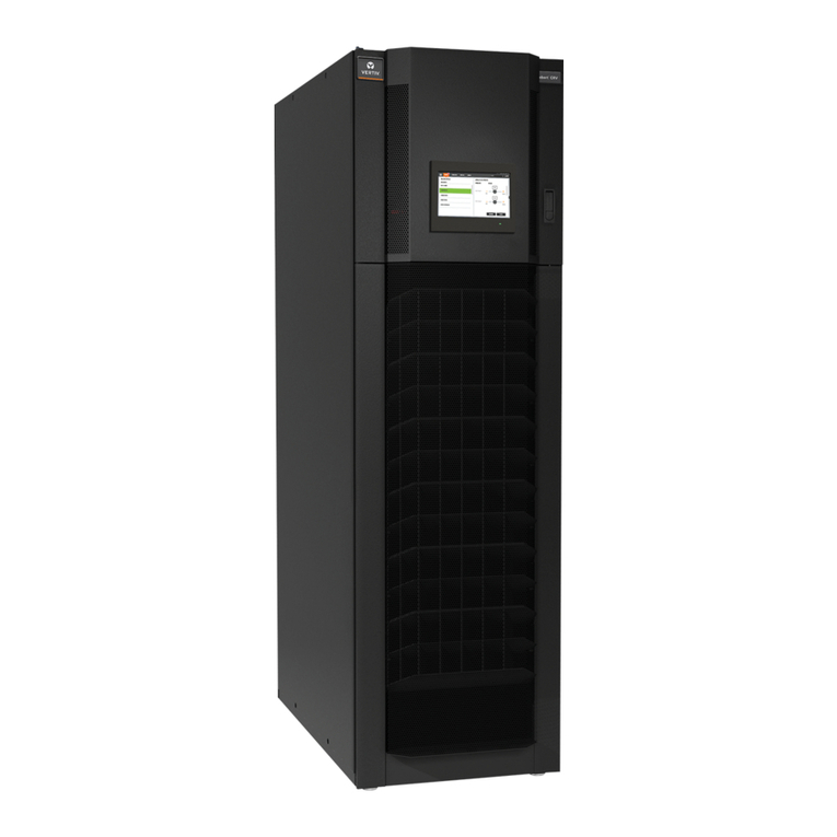
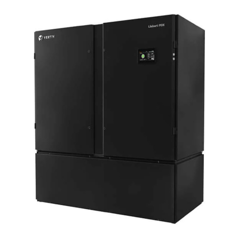
Vertiv MSC-ACE6W3 User manual

Rack Cooling 6.5 kW
User Manual

1 Product Overview
1.1 Product Model Description
The physical appearance of air conditioner is shown in Figure 1-1.
Indoor unit
condensing unit
Figure 1-1 Appearance of the air conditioner
The indoor unit is installed in the rack or at the ceiling. The condensing unit is mounted
external to the rack, preferably outside in an exposed environment.
1.2 Model Nomenclature
The nomenclature of the units is shown in Figure 1-2.
Figure 1-2 Nomenclature
Table 1-1 below mentions the description of the indoor and condensing units as per the
nomenclature.
Table 1-1 Model coding description
Sort
Model
Power
Supply
Description
Indoor unit
MSC-ACE6W3
220V/ 50Hz
6.5kW,PTC electric heater,Accessory box ,Chinese
Version
MSC-ACE6W4
220V/ 50Hz
6.5kW,Aaccessory box,Chinese Version

condensing
unit
MSC-ACC6W3
220V/ 50Hz
6.5kW,PTC electric heater,Accessory box,Chinese
Version
1.3 Indoor Unit
The main components of the indoor unit include evaporator coil,condensate drain tray,EC
fan,electronic expansion valve.The components of the indoor unit are depicted in Figure 1-3.
Figure 1-3 Indoor unit
1.4 condensing unit
The main components of the condensing unit include compressor, condenser coil and
condenser fan,The components of the condensing unit are depicted in Figure 1-4.
Figure 1-4 condensing unit

2. Mechanical Installation
2.1 Install air conditioning components
For models with optional heaters, keep a minimum distance of 150mm between the indoor
unit and the surrounding combustible surfaces. When testing the unit, please keep the
external static pressure of the test below 100Pa to prevent the unit's air volume from being
too low and the heater from overheating.
The indoor unit has been installed in the cabinet when it leaves the factory, and the condensing
unit is packaged and shipped separately. The customer site needs to reasonably place the
outdoor unit of the air conditioner, connect the copper pipes of the indoor unit and
condensing unit, extract the air from the system, and connect cables.
The condensing unit must be installed vertically. The condensing unit can either be installed
higher than the indoor unit or lower than the indoor unit. Figure 2-1 shows the scenario where
the condensing unit is installed higher than the indoor unit.
Figure 2-1 The Condensing unit is installed higher than the indoor unit
Figure 2-2 shows the scenario where the condensing unit is installed lower than the
indoor unit.

Figure 2-2 The Condensing unit is installed lower than the indoor unit
Following are the steps that need to be observed for the regular installation of the condensing
unit:
1. Place the condensing unit on the base
2. Use expansion bolts to fix the condensing unit on the base.
If there are multiple condensing units, they need to be placed on top of the other. The method
to implement placement of the condensing units on top of the other is shown in Figure 2-3.
Figure 2-3 Installing multiple condensing units one above the other

Note
Following points need to be taken during the installation of the condensing unit:
•The condensing unit must be placed appropriately in a safe place for maintenance. It also
should not be installed on the bottom floor of the public site. It should not be kept in a
residential area.
•It should not be kept in an environment where noise levels are considered crucial.
•Keep the condensing unit in a clean environment, free of debris, dust foreign matter. This
is done to avoid blocking of the heat exchanger and ensure an efficient cooling effect.
•There should be no steam, hot gas exhaust gas near the condensing unit.
•Preferably, keep above 450mm between the condensing unit and the wall, obstacles, or
adjacent devices. For normal condensing unit, if the condensing unit will be installed in an
outdoor environment, the recommended distance of the back side (return air side) from
the wall should be 200mm (7.87 in.). It is a must to provide these clearance distances to
ensure appropriate airflow across the condensing unit.
•Avoid keeping the condensing unit in places where snow may accumulate in the air intake
side and air outlet side.
•Preparing a base to bear the weight of the condensing unit is important where the base
should be at least 50mm (1.97in.) higher than the ground and 50mm (1.97in.) wider than
the condensing unit base.
•The condensing is around 44 kg (97 lbs.); therefore, utmost care must be taken while
removing it; any mishandling will result in severe injury and damage to the equipment.
Connect the indoor unit drain pipe
Down pipe drain
The indoor unit drains directly to the drain tray inside the cabinet, and the condensed water
is led to the drain trough or outdoors along the drain pipe at the bottom of the cabinet, as
shown in Figure 2-4. The drain pipe should not be placed in a position where the temperature
is freezing, and must be laid close to the ground. , The pipeline cannot be higher than the
height of the outlet of the drip tray.

Figure 2-4 Schematic diagram of down pipe drainage
2.2 Connecting the Copper Pipes to the Unit
General Principles
•Copper pipes with quick thread connectors must be used to connect the indoor and
condensing unit. If the pipe length exceeds the standard pipe length and a straight copper
pipe is used, in that case, piping joints must be brazed.
•Follow standard industry practices in selection and placement of pipes, system evacuation
charging with refrigerant (only when the pipeline is long). The standard refrigerant of
the unit is R410A. The charging amount is 2.3kg
•Take the pipeline pressure drop and the oil return to the compressor into consideration to
avoid oil leakage and clogging in parts of the system. Utmost care while considering these
factors minimizes the noise and vibration significantly.
•If the equivalent length exceeds 20m, or the vertical height difference between the indoor unit
and the outdoor unit exceeds the value shown in Table 2-1, please consult the manufacturer
before installation to confirm whether additional pipeline extension components are needed.
Table 2-1 Vertical height difference between indoor unit and condensing unit
relative position
Value
The outdoor unit is higher than the indoor unit
Max:15m
The outdoor unit is lower than the indoor unit
Max:5m
The Table 2-2 prescribes the equivalent length of the piping to be considered in the liquid
line piping for the bends and the elbows connector devices.
Table 2-2 Equivalent length for bends and elbows
Liquid pipe OD
(mm (inch))
Equivalent length (m (ft.))
90° elbow
45° elbow
T-type three way
9.52 (3/8)
0.21
0.10
0.74

(0.69)
(0.33)
(2.43)
12.7 (1/2)
0.24
(0.79)
0.12
(0.39)
0.76
(2.49)
Standard connecting pipe 5m: 6.5kW air conditioner adopts air pipe diameter 1/2 inch and
liquid pipe diameter 3/8 inch.
The longest connecting pipe is 30m.
6.5kW air conditioner, within 10m of connecting pipe, the diameter of the air pipe is 1/2
inch, and the diameter of the liquid pipe is 3/8 inch. The connecting pipe is 10-30m, the
diameter of the gas pipe is 5/8 inch, and the diameter of the liquid pipe is 1/2 inch.
2.Installation Notes of the connector
Both top as well as the bottom piping method are compatible with the unit. The connectors
of the unit are located on the indoor unit and condensing unit. Utmost care must be taken
while connecting the quick thread connector.
Read the following steps thoroughly before making the connection:
•Remove the dust-proof caps.
•Wipe the coupling seats and threaded surface with a clean cloth carefully.
•Lubricate the male thread with refrigerant oil.
•Thread the coupling halves together manually (by hand) to ensure that the threads mate
properly.
•Tighten the coupling body’s hexagon nut and union valve until a definite resistance is felt.6)
•Use a marker to draw a longitudinal line from the connecting nut to the end of the pipe;
then use two wrenches to tighten the nut a quarter turn to ensure air tightness. The
misalignment of the line indicates that it is tightly connected. During the installation
process, two wrenches must be used together. The operation of one wrench can easily
damage the connecting copper pipe of the valve.
Refer to Table 2-3 for recommended tightening torque values.
Table 2-3 Recommended torque value of quick connector
Coupling size (mm (inch))
Torque value (N.m)
9.52 (3/8)
7~8
12.7 (1/2)
8~9

3.Pipes to be connected
The refrigerant pipeline (gas side pipe and liquid side pipe) between the indoor unit and the
outdoor unit is shown in Figure 2-4
Figure 2-4 Schematic diagram of pipeline connection
1)The length of the copper pipe provided by the manufacturer is 5m. If you need a longer
pipe, please contact Vertiv or its sales agent.
2)The liquid side pipeline is the outlet refrigerant liquid pipeline of the condensing unit. The
liquid side tube should be selected with a reasonable diameter and length to ensure that
the pressure drop caused by the refrigerant liquid flowing through the liquid side tube
when the unit is running does not exceed 40kPa (5psi~6psi) .
3)Install and remove the connecting pipeline carefully so that the pipeline is not twisted or
damaged. Pipeline bending machine should be used to bend the pipe and then connect
with pipe joints.
4)If all refrigeration circuit pipelines need to be connected by welding, they should be brazed
and welded with silver electrodes.
5)Before use, the connecting pipe needs to be supported, leak tested, pressurized, and
vacuumed, and separated from the building with a vibration isolation frame.
6)In order not to damage the pipeline and reduce vibration when perforating the wall, it is
necessary to wrap some flexible soft materials around the pipeline.
7)This unit adopts quick connection mode.
8)Long connecting pipe system adds refrigerant: The series air conditioners have been filled
with a certain amount of refrigerant and lubricating oil according to the design when they
leave the factory. In the engineering installation, if the connecting pipeline between the
indoor and condensing units exceeds 10m, it is necessary to add refrigerant and lubricating
oil to make the system operate normally. The amount of refrigerant and lubricant
Refrigerant and refrigerant oil must be added in accordance with the following formula:
Refrigerant and refrigerant oil amount to be added (kg (lbs.)) = Adding refrigerant and
refrigerant oil amount per meter of the liquid pipe (kg/m. (lbs./ft)) × total length of the
extended liquid pipe (m. (ft))
Liquid pipe
Suction pipe

Table2-4 Additional refrigerant and refrigerant oil
Adding refrigerant amount per meter
kg/m
Adding refrigerant oil (FV50S) amount per meter ml/m
(ml/ft.)
0.1
11
note
1、Must be use the specific type of refrigerant and lubricating oil directly issued by the company
must be used, otherwise the compressor may be damaged. When adding refrigerant and
lubricating oil to the refrigeration system, please contact Vertiv technical customer service.
2、Adding inferior refrigerants or lubricating oil, or adding incorrect refrigerants or lubricating
oils will damage the system, and the quality problems caused by this will not be covered
by the warranty.
2.3 Pipeline connection inspection
Pipe inspection: focus on checking whether there is any leakage in the connecting pipes. The
copper pipes and valves of the internal machine need to be inspected with full insulation
cotton as shown in Figure 2-5.
Figure 2-5 Copper pipe connection inspection

3. Electrical Installation
This series of air conditioners need to be installed in accordance with national wiring
regulations.
3.1 Task introduction
Lines to be connected at the installation site:
1.Indoor unit power cable::1P3W power cable(1×L+N+PE), specification 1.5mm2.
2.Condensing unit power cable:1P3W power cable(1×L+N+PE), specification
0.75mm2.
3.Condensing unit compressor power cable:1P3W power cable(1×L+N+PE),
specification 1.5mm2.
4.Compressor Telecommunication Cable: standard twisted pair.
3.2 Precautions
This air conditioner is a professional equipment, used in industrial, commercial or other
professional occasions, and is not sold to the general public. Its total rated power is greater
than 1kW and conforms to the IEC61000-3-12 standard. It is necessary to provide an
interface between the user's power supply and the grid with a short-circuit ratio greater than
or equal to 250. The user needs to obtain permission from the power supply department to
ensure that the air conditioner is connected to the short-circuit ratio greater than or equal to
250 power supply.
1.All power and control wiring and ground connections must be in accordance with the
national and local electrician regulations.
2.See the equipment nameplate for the full load current. The cable sizes should meet the
local wiring standards and regulations.
3.Requirements for the main power supply:1P3W(220~240Vac,50Hz,1×L+N+
PE)。
4.The electrical installation and maintenance must be performed by authorized
professional installation personnel.
5.Before performing any electrical works, use a voltmeter to measure the power supply
voltage and make sure that the power supply has been switched off.
6.A proper rated circuit breaker should be installed so that the unit can be easily
disconnected from power supply .
7.If the power cord is damaged, it must be replaced by a professional maintenance person.
8.The input power supply needs to comply with national and local standards, and the
compressor power supply and fan power cords need to comply with national and local
outdoor use standards.

3.3 Cable Connection
The cable connections for the indoor unit are done through the cover panel at the back-side
of the unit as shown in Figure 3-1.
Figure 3-1 Schematic diagram of indoor unit cable connection
The cables of the condensing units are depicted in Figure 3-2.
Figure 3-2 Condensing unit cable connection
The cables of the indoor and the condensing units are depicted in Figure 3-3
RS485-2,Monitor
RS485-1,Monitor
RS485-3,Compressor communication
Display
Power cable220V
Compressor power cable
CAN1,Teamwork
CAN2,Teamwork
External water pump
Condenser fan power cable

Figure 3-3 Overview of the cabling connections
3.4 Connection check
Whether all external cable is corresponding, fastened, and the cable is fixed in the wire clamp.
Check whether the power cable corresponds. The connection cables of the indoor and
condensing machines should be checked for correct connection, as shown in Figure 3-4。
Figure 3-4 Check the connection cable
Monitor,RJ45*2 RS485
Power cable 220V
Condenser fan power cable
Compressor
Telecommunication Cable
Compressor power cable
Team work,
RJ45*2 CAN

Appendix I:Indoor Unit Wiring Diagram

Appendix II:Condensing Unit Wiring Diagram
This manual suits for next models
2
Table of contents
Other Vertiv Computer Hardware manuals
Popular Computer Hardware manuals by other brands

ekwb
ekwb EK-FC980 GTX TF5 Installation and mounting manuals

Air Monitor
Air Monitor VELTRON DPT 2500-plus Installation, operation and maintenance manual

ARTERY
ARTERY AT32 MCU CAN quick start guide

ADC
ADC Phase 5 Microprocessor AD-170 Service manual

ekwb
ekwb EK-Quantum Reflection2 PC-O11D EVO D5 PWM... user guide

Renesas
Renesas R0E510Y47LVB00 user manual