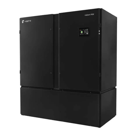
Vertiv Liebert CRV Installation and maintenance instructions

Liebert® CRV™
Row-basedCoolingSystem
600-mm and 300-mm Wide
Installer/User Guide

Technical Support Site
If you encounter any installation or operational issues with your product, check the pertinent section of
this manual to see if the issue can be resolved by following outlined procedures. For additional assistance,
visit https://www.VertivCo.com/en-us/support/

TABLE OF CONTENTS
7
13
13
13
14
15
17
17
17
19
20
20
20
21
22
24
25
26
27
27
1 Important Safety Instructions
2 Nomenclature and Components
2.1 Model-number Nomenclature
2.2 Component Location
2.3 Liebert CRV Description
2.4 Vertiv SmartRow Micro-Data Center Solution
3 Pre-installation PreparationandGuidelines
3.1 Planning Dimensions
3.2 Unit Weights
4 Equipment Inspection and Handling
4.1 Packaging Material
4.2 Handling the Unit while Packaged
4.2.1 Moving 600-mm (24-in. Models Using Rigging
4.3 Removing Packaging from 600-mm(24-in. Unit
4.4 Removing 600-mm (24-in. Models from the Skid
4.4.1 Reattaching Baffle Panel—600mm (24 in.
4.5 Removing Packaging from 300-mm (12-in. Unit
4.6 Removing 300-mm (12-in. Models from the Pallet
5 Installing in Enclosure Row
5.1 Adjusting Base Supports/Leveling Feet
5.2 Optional Tie-down Brackets for 300-mm (12-in. Units 29
5.2.1 What’s Included 29
5.2.2 Tools Required 30
5.2.3 Installing Tie-down Brackets on300-mm(12-in.) andonCabinetsofDifferentHeights 30
5.2.4 Installing Tie-down Brackets on300-mm(12-in.) andonCabinetsoftheSameHeight 31
6 Piping and Refrigerant Requirements 33
6.1 Refrigerant Piping and Charging 34
6.1.1 Refrigerant Piping Guidelines for Air-cooled Systems 35
6.2 Piping Guidelines for Liebert MC Condensers 36
6.2.1 Piping Layout and Condenser Positioning 37
6.2.2 Top or Bottom Connection for Refrigerant Piping onAir-cooled Units 38
6.2.3 Heat-rejection Line Sizes and Equivalent Lengths 39
6.2.4 Refrigerant Charge Requirements for Air-cooled Systems 40
6.2.5 Evacuation, Leak-testing, and Charging Air-cooled Systems without Receivers 43
6.2.6 Evacuation, Leak-testing, and Charging Air-cooled Systems withLiebertLee-Temp
“Flooded-condenser” Head-pressureControlSystem 47
6.2.7 Superheat and Refrigerant Charge Optimization 50
6.3 Fluid Piping forAir-cooled, Water/Glycol-cooledandChilled-waterPipingApplications 51
6.3.1 Water/Glycol Loop Piping Guidelines 51
6.3.2 Chilled-water Loop Piping 56
6.3.3 Humidifier Water-supply Line requirements 58
Vertiv | Liebert CRV Installer/User Guide | 3

6.3.4 Leak Checking for Unit and Field-installed Fluid Piping 59
6.3.5 Condensate-pump Drain Line Requirements 60
6.3.6 Condensate-pump Drain Piping for300-mm(12-in.) Models 61
6.3.7 Field-installed, Gravity-fed Drain Line Requirements 67
7 Electrical Connections 73
7.1 Power-supply Cable-connection Guidelines 73
7.2 Wiring Connections 73
7.3 Electrical Field-connection Descriptions 74
7.3.1 Locating the Serial Tag andRemovingtheElectricalPanelon600-mm (24-in.)Units 74
7.3.2 Cable-entry Points on 600-mm (24-in.) Units 76
7.3.3 Protective Features of Electrical Heaters—600-mm (24-in.) Units 77
7.3.4 Accessing the Electrical Panel on300-mm(12-in.) Units 77
7.3.5 Releasing the Electric-panel Lock 78
7.4 Protective Features of the Electronically-commutated (EC) Fans—All Models 79
8 Humidifier—600-mm (24-in.) Units Only 81
8.1 Principal of Operation 81
8.2 Connecting Water Supply to the Humidifier 82
8.3 Humidifier Start-up and Operation 82
8.3.1 Low Water Conductivity 83
8.4 Humidifier Canister Replacement 84
8.4.1 Removing the Old Canister 84
8.4.2 Mandatory Cleaning of the Drain Valve 85
8.4.3 Installing the New Canister 86
8.5 Humidifier Maintenance during Extended Shutdown 87
8.5.1 Humidifier Troubleshooting 87
8.5.2 Humidifier Troubleshooting Steps 89
9 Liebert iCOM Hardware Installation 91
9.1 Installing Wired Remote Sensors 91
9.1.1 Setting DIP switches and labeling 2T sensors 91
9.1.2 Terminating the last sensor on the CANbus link 94
9.1.3 Routing CANbus cable and preparing for sensor installation 95
9.1.4 Installing 2T sensors in the racks to monitor 100
9.1.5 Connecting the CANbus cable and ground 103
9.2 U2U Network Installation 105
9.2.1 Required network equipment 105
9.2.2 Plan wiring runs 105
9.2.3 U2U Wiring connection 105
9.2.4 Wiring Cooling Units without Wall-mount Displays 106
9.2.5 Wiring Cooling Units with Wall-mount Displays 108
10 Start-up 111
10.1 Checks to Perform after Start-up 112
10.2 Automatic Restart 112
Vertiv | Liebert CRV Installer/User Guide | 4

10.3 Chilled Water Valve— All Chilled-water Models 114
10.4 Adjust Baffles to Direct Air Properly 116
10.4.1 Adjusting Baffles—600-mm (24-in.) 116
10.4.2 Adjusting Blocker Plate—600-mm (12-in.) 117
10.4.3 Adjusting Baffles—300-mm (12-in.) 118
11 Monitoring and Managing theLiebertCRVwithLiebert®iCOM™ 121
11.1 Automatic restart after power failure 121
11.2 Loss-of-power notification 121
11.3 Variable-speed Fan Control 121
11.3.1 Manual fan-speed control 121
11.3.2 Automatic fan-speed control 122
11.3.3 Minimum Fan Speed 123
11.4 Compressor Protection 123
11.4.1 Advanced DX Freeze Protection 123
11.4.2 Advanced DX High-pressure Protection 123
11.4.3 High-pressure Lock-off 123
11.4.4 High-temperature Lock-off for Digital-scroll compressors 124
11.4.5 Short-cycle Protection 125
11.4.6 Motorized Ball Valves forWater/Glycol-cooledUnitswithDigital-scroll Compressors 125
12 Troubleshooting 127
13 Maintenance 133
13.1 Safety Instructions 133
13.2 Facility Fluid and Piping Maintenance forWaterandGlycolSystems 134
13.3 Glycol Solution Maintenance 134
13.4 Spare Parts 134
13.5 Maintenance Schedule 134
13.5.1 Thermostatic Expansion Valve (TXV) Maintenance 136
13.5.2 Determining Suction Superheat 136
13.5.3 Adjusting Superheat Setting with the TXV 136
13.6 Inspect and Replace the Air Filters—600-mm (24-in.) Models 137
13.7 Inspect and Replace the Air Filters—300-mm (12-in.) Models 139
13.8 Condensate-drain and Condensate-pump System Maintenance 140
13.8.1 Condensate Drain 140
13.8.2 Condensate Pump, Dual-Float 140
13.9 Air-Cooled Condenser and Drycooler Maintenance 141
13.10 Electric Reheat Maintenance 141
13.11 Fan Replacement 141
13.11.1 Replacing a Fan in 600-mm (24-in.) Models 141
13.11.2 Replacing a Fan in 300-mm (12-in.) Models 142
13.12 Considerations when Dismantling the Unit 144
13.13 F-Gas Regulation (EC) No. 842/2006 144
14 Preventive Maintenance Worksheet 147
Vertiv | Liebert CRV Installer/User Guide | 5

1 IMPORTANT SAFETY INSTRUCTIONS
SAVE THESE INSTRUCTIONS
This manual contains important safety instructions that should be followed during the installation and
maintenance of the Liebert CRV. Read this manual thoroughly before attempting to install or operate this
unit.
Only qualified personnel should move, install or service this equipment.
Adhere to all warnings, cautions, notices and installation, operating and safety instructions on the unit
and in this manual. Follow all installation, operation and maintenance instructions and all applicable
national and local building, electrical and plumbing codes.
Any operation that requires opening doors or equipment panels must be carried out only by properly-
trained and qualified personnel.
To identify the unit model and serial number for assistance or spare parts, locate the identification label
on the unit. The label is inside the door on 600 mm (24 in.) units and at the electrical box on 300 mm (12
in.) units.
A warning label on the front and back panels reminds users that:
•the Liebert CRV restarts automatically
•the main switch must be opened before opening the internal compartments for any operation.
WARNING! Arc flash and electric shock hazard. Open all local and remote electric power
disconnect switches, verify with a voltmeter that power is Off and wear personal protective
equipment (PPE) per NFPA 70E before working within the electric control enclosure. Failure to
comply can cause serious injury or death. Customer must provide earth ground to unit, per
NEC, CEC and local codes, as applicable. Before proceeding with installation, read all
instructions, verify that all the parts are included and check the nameplate to be sure the
voltage matches available utility power. The Liebert controller does not isolate power from the
unit, even in the “Unit Off” mode. Some internal components require and receive power even
during the “Unit Off” mode of the controller. The factory-supplied, optional disconnect switch
is inside the unit. The line side of this switch contains live high-voltage. The only way to ensure
that there is NO voltage inside the unit is to install and open a remote disconnect switch. Refer
to unit electrical schematic. Follow all local codes.
WARNING! Risk of explosive discharge from high-pressure refrigerant. Can cause loss of
refrigerant, environmental pollution, injury or death. This unit contains fluids and gases under
high pressure. Relieve pressure before working with piping.
WARNING! Risk of refrigerant system rupture or explosion from overpressurization. Can cause
equipment damage, injury or death. Use extreme caution when charging the refrigerant system.
Do not pressurize the system higher than the design pressure marked on the unit's nameplate.
Vertiv | Liebert CRV Installer/User Guide | 7

WARNING! Risk of contact with high-speed, rotating fan impeller blades. Can cause injury or
death. Open all local and remote electrical-supply disconnect switches, verify with a voltmeter
that power is off, and verify that all fan impellers have stopped rotating before working in the
unit.
WARNING! Risk of top-heavy unit falling over. Improper handling can cause equipment
damage, injury or death. Read all of the following instructions and verify that all lifting and
moving equipment is rated for the weight of the unit before attempting to move, lift, remove
packaging from or prepare the unit for installation.
WARNING! Risk of unsecured unit rolling off skid. Can cause equipment damage, injury or
death. The 300-mm (12-in.) DX unit is on casters. Ensure that the unit/skid is located on a flat
surface before loosening the hardware securing the to its shipping pallet.
WARNING! Risk of hair, clothing and jewelry entanglement with high speed rotating fan blades.
Can cause equipment damage, serious injury or death. Keep hair, jewelry and loose clothing
secured and away from rotating fan blades during unit operation.
WARNING! Risk of contact with extremely hot and/or cold surfaces. Can cause equipment
damage, injury and death. Open all local and remote electric power supply disconnect switches,
verify with a voltmeter that power is Off, and verify that all components have reached a
temperature that is safe for human contact or wear appropriate, OSHA-approved PPE before
working within the electric connection enclosures or unit cabinet. Perform maintenance only
when the system is de-energized and component temperatures have become safe for human
contact.
CAUTION: Risk of contact with sharp edges, splinters, and exposed fasteners. Can cause
injury. Only properly trained and qualified personnel wearing appropriate, OSHA-approved PPE
should attempt to move, lift, remove packaging from or prepare the unit for installation.
NOTICE
Risk of oil contamination with water. Can cause equipment damage.
Liebert systems require the use of POE (polyolester) oil. POE oil absorbs water at a much
faster rate when exposed to air than previously used oils. Because water is the enemy of a
reliable refrigeration system, extreme care must be used when opening systems during
installation or service. If water is absorbed into the POE oil, it will not be easily removed and will
not be removed through the normal evacuation process. If the oil is too wet, it may require an oil
change. POE oils also have a property that makes them act as a solvent in a refrigeration
system. Maintaining system cleanliness is extremely important because the oil will tend to
bring any foreign matter back to the compressor.
Vertiv | Liebert CRV Installer/User Guide | 8

NOTICE
Risk of improper refrigerant charging. Can cause equipment damage.
Refrigerant charge must be weighed into air-cooled compressorized systems before they are
started. Starting scroll and digital scroll compressors without proper refrigerant charging can
cause the compressors to operate at less than 5°F (–15°C) evaporator temperature and at less
than 20psig (138kPa). Operation for extended periods at less than 20psig (138kPa) can
cause premature compressor failure.
NOTICE
Risk of clogged or leaking drain lines. Can cause equipment and building damage.
This unit requires a water drain connection. Drain lines must be inspected at start-up and
periodically, and maintenance must be performed to ensure that drain water runs freely
through the drain system and that lines are clear and free of obstructions and in good
condition with no visible sign of damage or leaks. This unit may also require an external water
supply to operate.
Improper installation, application and service practices can result in water leakage from the
unit. Water leakage can result in catastrophic and expensive building and equipment damage
and loss of critical data center equipment.
Do not locate unit directly above any equipment that could sustain water damage.
We recommend installing a monitored fluid-detection system to immediately discover and
report coolant-fluid system and condensate drain-line leaks.
Vertiv | Liebert CRV Installer/User Guide | 9

NOTICE
Risk of piping-system corrosion and freezing fluids. Can cause leaks resulting in equipment
and very expensive building damage. Cooling coils, heat exchangers and piping systems are at
high risk of freezing and premature corrosion. Fluids in these systems must contain the proper
antifreeze and inhibitors to prevent freezing and premature coil, piping and heat exchanger
corrosion. The water or water/glycol solution must be analyzed by a competent local water
treatment specialist before start up to establish the inhibitor and antifreeze solution
requirement and at regularly scheduled intervals throughout the life of the system to
determine the pattern of inhibitor depletion.
The complexity of water/glycol solution condition problems and the variations of required
treatment programs make it extremely important to obtain the advice of a competent and
experienced water treatment specialist and follow a regularly scheduled coolant fluid system
maintenance program.
Water chemistry varies greatly by location, as do the required additives, called inhibitors, that
reduce the corrosive effect of the fluids on the piping systems and components. The chemistry
of the water used must be considered, because water from some sources may contain corrosive
elements that reduce the effectiveness of the inhibited formulation. Sediment deposits prevent
the formation of a protective oxide layer on the inside of the coolant system components and
piping. The water/coolant fluid must be treated and circulating through the system
continuously to prevent the buildup of sediment deposits and or growth of sulfate reducing
bacteria.
Proper inhibitor maintenance must be performed in order to prevent corrosion of the system.
Consult glycol manufacturer for testing and maintenance of inhibitors.
Commercial ethylene glycol, when pure, is generally less corrosive to the common metals of
construction than water itself. It will, however, assume the corrosivity of the water from which it
is prepared and may become increasingly corrosive with use if not properly inhibited.
We recommend installing a monitored fluid-detection system that is wired to activate the
automatic-closure of field-installed coolant-fluid supply and return shut-off valves to reduce
the amount of coolant-fluid leakage and consequential equipment and building damage. The
shut-off valves must be sized to close-off against the maximum coolant-fluid system pressure
in case of a catastrophic fluid leak.
NOTICE
Risk of frozen pipes and corrosion from improper coolant mixture. Can cause equipment
damage and building.
When piping or the cooling unit may be exposed to freezing temperatures, charge the system
with the proper percentage of glycol and water for the coldest design ambient temperature.
Automotive antifreeze is unacceptable and must NOT be used in any glycol fluid system. Use
only HVAC glycol solution that has been prepared by industry practices.
NOTICE
Risk of no-flow condition. Can cause equipment damage. Do not leave the water/coolant fluid-
supply circuit in a no-flow condition. Idle fluid allows the collection of sediment that prevents
the formation of a protective oxide layer on the inside of tubes. Keep unit switched On and
water/coolant fluid-supply circuit system operating continuously.
Vertiv | Liebert CRV Installer/User Guide | 10

NOTICE
Risk of improper water supply. Can reduce humidifier efficiency or obstruct humidifier
plumbing.
Do not use completely demineralized water with this unit. The water must contain minerals for
the electrode principle to work.
Do not use a hot water source. It will cause deposits that will eventually block the fill-valve
opening.
NOTICE
Risk of water backing up in the drain line. Leaking and overflowing water can cause equipment
and building damage.
Do not install an external trap in the drain line. This line already has a factory-installed trap
inside the cabinet (Except for 300-mm (12-in.) Chilled-water models).
This line may contain boiling water. Use copper or other suitable material for the drain line.
Sagging condensate drain lines may inadvertently create an external trap.
NOTICE
Risk of doorway/hallway interference. Can cause unit and/or structure damage. The unit may
be too large to fit through a doorway or hallway while on the skid. Measure the unit and
passageway dimensions, and refer to the installation plans prior to moving the unit to verify
clearances.
NOTICE
Risk of damage from forklift. Can cause unit damage. Keep tines of the forklift level and at a
height suitable to fit below the skid and/or unit to prevent exterior and/or underside damage.
NOTICE
Risk of improper storage. Can cause unit damage.
Keep the unit upright, indoors and protected from dampness, freezing temperatures and
contact damage.
NOTICE
Risk of release of hazardous substances into the environment. Can cause environmental
pollution and violation of environmental regulations.
The Liebert CRV contains substances and components hazardous for the environment
(electronic components, refrigerating gases and oils). At the end of its useful life, the
LiebertCRV must be dismantled by specialized refrigerating technicians. The unit must be
delivered to suitable centers specializing in the collection and disposal of equipment
containing hazardous substances.
NOTE: The Liebert indoor cooling unit has a factory-installed high pressure safety switch in the high-
side refrigerant circuit. A pressure relief valve is provided with Liebert Lee-Temp™ condensers. Consult
your local building code to determine whether the Liebert MC condensers will require field-provided
pressure-relief devices.
Vertiv | Liebert CRV Installer/User Guide | 11

Agency Listed
Standard 60-Hz units are CSA certified to the harmonized U.S. and Canadian product safety standard
CSA C22.2 No 236/UL 1995 for Heating and Cooling Equipment and are marked with the CSA c-us logo.
Vertiv | Liebert CRV Installer/User Guide | 12

2 NOMENCLATURE AND COMPONENTS
This section describes the model-number configuration for Liebert CRV units and components.
2.1 Model-number Nomenclature
The tables describe the 25-digitconfigurationnumber. The 14-digit model number consists of the first 10
digits and last 4 digits of the configuration number.
For the full description of configuration and model number refer to Model-number Nomenclature Detail
on page153.
MODEL NUMBER DIGITS 1 TO 10 MODEL DETAILS MODEL NUMBER DIGITS 11 TO 14
1 2 3 4 5 6 7 8 9 10 11 12 13 14 15 16 17 18 19 20 21 22 23 24 25
C R 0 2 0 R A 1 C 7 S H 1 8 1 1 E L 1 0 P A — — —
Digits 1-2 - Unit Family Digit 14 - Air Filter
Digits 3-5 - Nominal Capacity, kW Digit 15 - Water/Glycol Valve Type
Digit 6 - Row-Based, Unit Depth Digit 16 - Enclosure
Digit 7 - System Type Digit 17 - High-Voltage Options
Digit 8 - Fan Type Digit 18 - Option Package
Digit 9 - Power Supply Digit 19 - Liebert IntelliSlot™ Housing
Digit 10 - Cooling System Digit 20 - Future Options
Digit 11 - Humidifier Digit 21 - Packaging With Ramp
Digit 12 - Control System Digit 22 - Special Features
Digit 13 - Reheat Digits 23-25 - Factory Configuration Number
2.2 Component Location
The unit component locations are described in the submittal documents included in the Submittal
Drawings on page156.
The following table lists the relevant documents by number and title.
DOCUMENT NUMBER TITLE
DPN003738 Component Locations, 600mm (24in.) Models
DPN003583 Component Location, 300mm (12in.) Air Cooled Models
DPN003585 Component Location, 300mm (12in.) Water Glycol Cooled Models
DPN003584 Component Location, 300mm (12in.) Chilled Water Models
Table 2.1 Component-location Drawings
Vertiv | Liebert CRV Installer/User Guide | 13

2.3 Liebert CRV Description
The Liebert CRV is a precision cooling unit available in compressorized (air-, water- or glycol-cooled) and
chilled-water configurations to be installed within a row of high-density computing racks in a “hotaisle-
coldaisle” configuration.
Air enters the rear of the CRV from the hot aisle, is filtered, cooled and conditioned, then discharged into
the cold aisle. The CRV provides all the necessary functions of a standard Thermal Management unit,
including cooling, heating, humidification, dehumidification, air filtration, condensate management,
temperature control, alarm monitoring and data communication. (The 300 mm [12 in.] models do not
provide heating, humidification or dehumidification.) The CRV is optimized for maximum cooling capacity
in a minimal footprint.
Figure 2.1 Liebert CRV, front and rear views
ITEM DESCRIPTION
1 Front view
2 Rear view
3 600-mm (24-in.) DX and CW models
4 300-mm (12-in,) DX models
5 300-mm (12-in.) CW models
Vertiv | Liebert CRV Installer/User Guide | 14

2.4 Vertiv SmartRow Micro-Data Center Solution
The Vertiv™ SmartRow DCX is a comprehensive, micro-data center in a row. Starting with the IT
requirements, all of the associated remote management, monitoring and infrastructure are configured to
address the initial and future needs of the rack-mount equipment. This approach simplifies the entire
process, from selection through to deployment, reducing the time, complexity and costs associated with
alternative approaches. The factory-engineered SmartRow platform leverages the Liebert CRV as part of
its thermal-management system. For more information visit, www.VertivCo.com/SmartRowDCX.
Figure 2.2 SmartRow DCX
Vertiv | Liebert CRV Installer/User Guide | 15

Vertiv | Liebert CRV Installer/User Guide | 16
This page intentionally left blank.

3 PRE-INSTALLATION PREPARATIONANDGUIDELINES
NOTE: Before installing unit, determine whether any building alterations are required to run piping,
wiring and duct work. Follow all unit dimensional drawings and refer to the submittal engineering
dimensional drawings of individual units for proper clearances.
Refer to Model-number Nomenclature on page13 and the appropriate submittal drawings, to determine
the type of system being installed and anticipate building alterations, piping and duct work needed.
The unit dimensions, pipe-connection locations, and piping schematics are described in the submittal
documents included in the Submittal Drawings on page156.
•Verify that the floor is level, solid and sufficient to support the unit. See Table 3.2 below. for
unit weights.
•Confirm that the room is properly insulated and has a sealed vapor barrier.
•For proper humidity control, keep outside or fresh air to an absolute minimum (less than 5% of
total air circulated in the room).
•Do not install a Liebert CRV in an alcove or at the end of a long, narrow room.
•Install the units as close as possible to the largest heat load.
•Allow at least the minimum recommended clearances for maintenance and service. See the
appropriate submittal drawings for dimensions.
•We recommend installing an under-floor water detection system. Contact your Vertiv™
representative for information.
3.1 Planning Dimensions
The unit, floor stand, and plenum dimensions are described in the submittal documents included in the
Submittal Drawings on page156.
The following table lists the relevant documents by number and title.
DOCUMENT NUMBER TITLE
DPN001791 Cabinet and Floor Planning Dimensional Data, 600 mm (24 in.)
DPN002807 Cabinet and Floor Planning Dimensional Data, 300 mm (12 in.)
Table 3.1 Dimension Planning Drawings
3.2 Unit Weights
MODEL NO. UNIT WIDTH
WEIGHT ± 5%, LB (KG)
AIR-COOLED WATER/GLYCOL-COOLED CHILLED WATER
CR019
300 mm (12 in.)
507 (230) 545 (247) —
CR032 — — 418 (190)
CR020
600 mm (24 in.)
739 (335) 772 (350) —
CR035 805 (365) 849 (385) —
CR040 — — 728 (330)
Table 3.2 Weights without packaging
Vertiv | Liebert CRV Installer/User Guide | 17

MODEL NO.
DOMESTIC PACKAGING, LB (KG) EXPORT PACKAGING, LB (KG)
AIR WATER/GLYCOL CHILLED WATER AIR WATER/GLYCOL CHILLED WATER
CR019 649 (294) 687 (311) — 721 (327) 782 (355) —
CR032 — — 560 (254.0) — — 683 (309.8)
CR020 846 (384) 879 (399) — 953 (432) 986 (447) —
CR035 912 (414) 956 (434) — 1019 (462) 1063 (482) —
CR040 — — 835 (379) — — 942 (427)
Table 3.3 Shipping weights
Vertiv | Liebert CRV Installer/User Guide | 18

4 EQUIPMENT INSPECTION AND HANDLING
SAFETY INFORMATION
WARNING! Risk of top-heavy unit falling over. Improper handling can cause equipment
damage, injury or death. Read all of the following instructions and verify that all lifting and
moving equipment is rated for the weight of the unit before attempting to move, lift, remove
packaging from or prepare the unit for installation. Unit weights are specified in Table 3.2 on
page17 and Table 3.3 on page18.
CAUTION: Risk of contact with sharp edges, splinters, and exposed fasteners. Can cause
injury. Only properly trained and qualified personnel wearing appropriate, OSHA-approved PPE
should attempt to move, lift, remove packaging from or prepare the unit for installation.
NOTICE
Risk of doorway/hallway interference. Can cause unit and/or structure damage. The unit may
be too large to fit through a doorway or hallway while on the skid. Measure the unit and
passageway dimensions, and refer to the installation plans prior to moving the unit to verify
clearances.
NOTICE
Risk of damage from forklift. Can cause unit damage. Keep tines of the forklift level and at a
height suitable to fit below the skid and/or unit to prevent exterior and/or underside damage.
NOTICE
Risk of improper storage. Keep the unit upright, indoors and protected from dampness,
freezing temperatures and contact damage.
Upon arrival of the unit and before unpacking:
•Verify that the labeled equipment matches the bill of lading.
•Carefully inspect all items for visible or concealed damage.
•Report damage immediately to the carrier and file a damage claim with a copy sent to Vertiv™
or to your sales representative.
•For initial access use a 7/32-in. Allen wrench for panel removal.
Equipment Recommended for Handling the Unit:
•Forklift
•Pallet jack
•Piano jacks
•Slings
•Spreader bars
Vertiv | Liebert CRV Installer/User Guide | 19

4.1 Packaging Material
All material used to package this unit is recyclable. Please save for future use or dispose of the
material appropriately.
4.2 Handling the Unit while Packaged
Transport the unit with a forklift or pallet jack. See Moving 600-mm (24-in.) Models Using Rigging below
for additional handling option for the 600-mm (24-in) unit.
When using a forklift or pallet jack:
•Make sure that the forks (if adjustable) are spread to the widest allowable distance that will fit
under the skid.
•Make sure the fork length is suitable for the skid length. Skid length for 600-mm (24-in.) model
is 60in (1524mm). Skid length for 300-mm (12-in.) model is 54in. (1372mm)
•Do not lift the packaged unit any higher than 4in. (102 mm). All personnel except those
moving the unit must be kept 12ft (3.7m) or more from the unit while it is being moved.
•If the unit must be lifted higher than 4in. (102 mm), all personnel not directly involved in
moving the unit must be 20ft (5m) or more from the unit.
•Always refer to the location of the center-of-gravity indicators when lifting the unit, see Figure
4.1 below.
Figure 4.1 Center-of-gravity indicator
4.2.1 Moving 600-mm (24-in.) Models Using Rigging
1. Use a pallet jack or forklift to raise the packaged unit.
2. Place slings under the skid runners, equally spacing the slings to make sure the unit is
balanced, see Figure 4.2 on the facing page.
3. Lower the unit and remove the pallet jack or forklift.
4. Connect the slings to the lifting device, using spreader bars or similar equipment to protect the
unit, see Figure 4.2 on the facing page.
NOTE: Wrapping one or two more straps around the middle of the unit will improve stability when it is
lifted.
5. Move the unit to its installation location. Two or more properly trained and qualified personnel
are required to move the unit to its installation location.
6. Lower the unit and remove the slings.
Vertiv | Liebert CRV Installer/User Guide | 20
Other manuals for Liebert CRV
2
Table of contents
Other Vertiv Computer Hardware manuals