Vertiv Liebert CRV CRD25 User manual

Liebert® CRV CRD25 and CRD35
User Manual (Original Instructions)
25 kW and 35 kW, 50 Hz, Row-Based Cooling System

Vertiv™ Liebert® CRV CRD25 and CRD35 Row-Based Cooling System User Manual
Technical Support Site
If you encounter any installation or operational issues with your product, check the pertinent section of this
manual to see if the issue can be resolved by following outlined procedures.
Visit https://www.vertiv.com/en-emea/support/ for additional assistance.
The information contained in this document is subject to change without notice
and may not be suitable for all applications. While every precaution has been
taken to ensure the accuracy and completeness of this document, Vertiv
assumes no responsibility and disclaims all liability for damages result from
use of this information or for any errors or omissions.
Refer to local regulations and building codes relating to the application,
installation, and operation of this product. The consulting engineer, installer,
and/or end user is responsible for compliance with all applicable laws and
regulations relation to the application, installation, and operation of this
product.
The products covered by this instruction manual are manufactured and/or sold
by Vertiv. This document is the property of Vertiv and contains confidential
and proprietary information owned by Vertiv. Any copying, use, or disclosure of
it without the written permission of Vertiv is strictly prohibited.
Names of companies and products are trademarks or registered trademarks of
the respective companies. Any questions regarding usage of trademark names
should be directed to the original manufacturer.
Vertiv™ Liebert® CRV CRD25 and CRD35 Row-Based Cooling System User Manual

TABLE OF CONTENTS
1 Important Safety Instructions 1
2 Product Overview 3
2.1 Model Nomenclature 3
2.2 Name Plate and Components 4
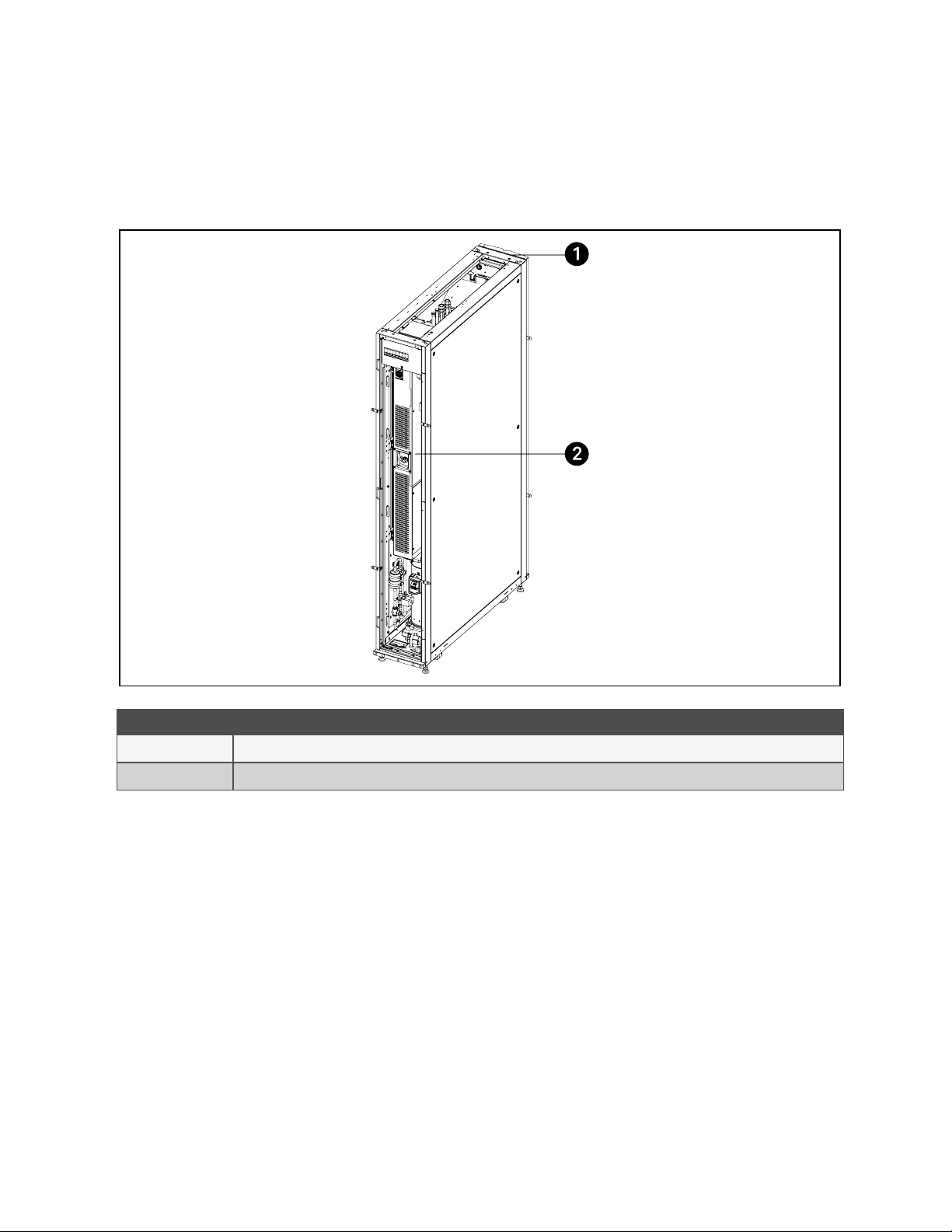
2.3 Component Location 6
2.4 Accessories 7
2.5 System Data 8
3 Pre-installation Preparation 11
3.1 Tools Required 11
3.2 Dimensions and Weights 12
3.3 Clearance Requirements 13
3.4 Inspecting the Unit 13
3.5 Moving the Packaged Unit 14
3.6 Unpacking the Unit 14
3.7 Removing the Unit from the Pallet 15
4 Installing in Enclosure Row 19
4.1 Leveling the Unit 19
4.2 Removing the Feet and Fixing the Unit (Optional) 19
4.3 Combining the Unit with Adjacent Cabinets 20
4.4 Location of the Main Grounding Point 21
4.5 Removing Compressor Fixing Plates 22
4.6 Installing Top Frame and Front Frame (Optional) 24
4.6.1 Installing the Top Frame without the Front Frame 24
4.6.2 Installing the Top Frame and the Front Frame 27
5 Piping and Refrigeration Connections 31
5.1 General Arrangement 32
5.2 Connecting Drainage Pipes 37
5.2.1 Top Connection 37
5.2.2 Bottom Connection 37
5.3 Connecting Water Supply for Humidifier 37
5.3.1 Top Connection 38
5.3.2 Bottom Connection 38
5.4 Connecting Gas Pipe and Liquid Pipe 38
6 Electrical Connections 41
6.1 Connecting Power Supply Cable 41
6.2 Connecting Communications Cables 43
6.2.1 General Arrangement 43
6.2.2 Connecting Communications Cable between Evaporator and Condenser 45
i
Vertiv™ Liebert® CRV CRD25 and CRD35 Row-Based Cooling System User Manual

6.2.3 Connecting the Water Leakage Sensor (Optional) 45
6.2.4 Connecting the Static Pressure Sensor (Optional) 45
6.2.5 Connecting the Monitor Device to Unity Card (Optional) 45
6.2.6 Connecting Alarm Device (Optional) 45
6.2.7 Connecting Remote Temperature Sensors (Optional) 45
6.2.8 Connecting the Remote On/Off Device (Optional) 46
6.2.9 Connecting for Teamwork 46
7 Start-up 49
7.1 Charging Refrigerant and Lubricating Oil 49
7.1.1 Amount of Refrigerant and Lubricating Oil 49
7.1.2 Evacuating the Unit 51
7.1.3 Adding Lubricating Oil 53
7.1.4 Charging the Refrigerant 53
7.2 Start-up Procedure 54
7.2.1 First Start-up (or After Long Standstill) 54
7.2.2 Automatic Restart 54
8 HMI Display 55
8.1 Appearance 55
8.2 Main Functions 56
8.2.1 Home Page 56
8.2.2 Control Mode 58
8.3 Menu Structure and Parameters 58
8.4 Alarm Information 58
8.5 Teamwork Control 59
9 Maintenance 61
9.1 Maintenance Schedule 61
9.2 Air Filters 62
9.3 Condensate Drain and Condensate Pump 62
9.4 Condenser 63
9.5 Fan 63
9.6 Electric Heater 64
9.7 Humidifier 66
9.8 Refrigeration Circuit 67
9.9 Dismantling the unit 68
9.10 Troubleshooting 68
10 Regulation (EU) 71
11 Appendices 73
Appendix A: Menu Structure 73
Appendix B: Alarm Table 78
Appendix C: Conformity to EU Directives 80
Appendix D: Technical Support and Contacts 81
ii
Vertiv™ Liebert® CRV CRD25 and CRD35 Row-Based Cooling System User Manual

1 Important Safety Instructions
NOTE: Before moving, installing or servicing this unit, please read the Safety Instructions sheet provided as a
separate document shipped with the unit.
1 Important Safety Instructions 1
Vertiv™ Liebert® CRV CRD25 and CRD35 Row-Based Cooling System User Manual

1 Important Safety Instructions
2
This page intentionally left blank
Vertiv™ Liebert® CRV CRD25 and CRD35 Row-Based Cooling System User Manual

2 Product Overview
The Vertiv™ Liebert® CRV CRD25 and CRD35 row-based cooling units are specifically created and designed for small to
medium data centers, computer rooms, equipment rooms, and similar high heat density environments.
The CRD25 and CRD35 indoor units are used together with the CCD25 and CCD35 condensers. CRD25 and CRD35 provide
power to CCD25 and CCD35 and control their operation.
2.1 Model Nomenclature
The following tables describe the model number for the Vertiv™ Liebert® CRV CRD25 and CRD35 cooling units.
Model Number
1 2 3 4 5 6 7 8 9 10 11 12
C R D 2 5 5 - P D 0 0 A
Table 2.1 CRD25 Model Number Example
Digit Variable Description
1 C
Vertiv™ Liebert® CRV
2 R
3 D Air cooled
4
25, 35 Model number
5
6 5 400 V, 3-phase, 50 Hz, CE
7 - Separator
8 P Reheat and humidifier
9 D Dual power supply
10 0 R410A refrigerant
11 0 Free digit
12 A- Z Revision
Table 2.2 CRD25 and CRD35 Model Number Digit Definitions
2 Product Overview 3
Vertiv™ Liebert® CRV CRD25 and CRD35 Row-Based Cooling System User Manual

2.2 Name Plate and Components
Figure 2.1 Name Plate Location
Item Description
1 Front door
2 Name plate on the side cover of the electrical box 2
2 Product Overview
4
Vertiv™ Liebert® CRV CRD25 and CRD35 Row-Based Cooling System User Manual

Figure 2.2 Vertiv™ Liebert® CRV CRD25 and CRD35 Name Plate Information
Name Plate Information Description Name Plate Information Description
UNIT Unit defined by 6 digits WEIGHT NET/GROSS Net weight and gross weight of the
unit
MODEL Model defined by 12 digits REFRIGERANT CHARGE The amount of refrigerant charged
on site
REFRIGERANT Type of the refrigerant GWP Global warming potential
2 Product Overview 5
Vertiv™ Liebert® CRV CRD25 and CRD35 Row-Based Cooling System User Manual

2.3 Component Location
Figure 2.3 Vertiv™ Liebert® CRV CRD25 Component Location
Item Description Item Description
1 Side panel 8 Electrical box 2
2 Top panel 9 Compressor
3 Filter 10 Heat exchanger
4 Rear door 11 Humidifier
5 Bottom panel 12 EC fan
6 Leveling foot 13 Front door
7 Caster 14 Human machine interface (HMI)
display
2 Product Overview
6
Vertiv™ Liebert® CRV CRD25 and CRD35 Row-Based Cooling System User Manual

Figure 2.4 Vertiv™ Liebert® CRV CRD35 Component Location
Item Description Item Description
1 Side panel 8 Electrical box 2
2 Top panel 9 Compressor
3 Filter 10 Heat exchanger
4 Rear door 11 Humidifier
5 Bottom panel 12 EC fan
6 Leveling foot 13 Front door
7 Caster 14 Human machine interface (HMI)
display
2.4 Accessories
The accessories provided with the unit are listed in the table below.
2 Product Overview 7
Vertiv™ Liebert® CRV CRD25 and CRD35 Row-Based Cooling System User Manual

Component Quantity
Remote temperature sensor (IRMS01T) 1
Cable for remote temperature sensor 2
Water leakage detection board (CM20AR) 1
Bracket for water leakage detection board 1
Cable for water leakage detection board 1
Rc1/2 in. brass humidifier pipe connector 1
Rc1/2 in. brass drainage connector with plug 1
ø 9.52 mm (3/8 in.) black steam pipe 0.8
Plastic parts 4
M12 x 30 hexagon bolt 8
M5 x 12 cross grooved countersunk head screw 5
Stainless steel hose clamp 1
L-shaped baying bracket 8
Cabinet guide rail 2
User manual 1
Unit circuit diagram 1
EU declaration of conformity 1
Product inspection report 1
Table 2.3 Accessories
2.5 System Data
Parameter CRD25 CRD35
Width mm (in.) 300 (11.8) 600 (23.6)
Input power AC 400V 3Ph+N+PE 50Hz AC 400V 3Ph+N+PE 50Hz
Total airflow rated/maximum m3/h (CFM) 5200/5500 (3061/3237) 8000/8500 (4709/5003)
Total fan power consumption maximum kW 1.215 1.234
Number of fans 6 8
Heating capacity kW 3 6
Humidification capacity kg/h (lb/h) 2 (4.4) 2 (4.4)
Condensate pump capacity L/min @5 m 3.5 3.5
Air filtration efficiency G4 G4
Table 2.4 Technical Specifications
2 Product Overview
8
Vertiv™ Liebert® CRV CRD25 and CRD35 Row-Based Cooling System User Manual

Parameter Design Condition (Minimum) Design Condition (Maximum)
Unit entering air
Temperature °C (°F) 24 (75.2) 45 (113)
Relative humidity 17% 60%
Storage conditions Temperature °C (°F) -40 (-40) 70 (158)
Outdoor air Temperature °C (°F) -20 (-4)
48 (118.4)
Note: Unit remains operational up to
52 °C (125.6 °F) with reduced
capacity
With low ambient kit Low ambient kit -35 (-31) 48 (118.4)
Power supply tolerances
Voltage ± 10%
Frequency ± 3 Hz
Equivalent length of pipe between evaporator and condenser m (ft) - 120 (393.7)
Height between evaporator and
condenser m (ft)
Condenser placed higher than
evaporator - 30 (98.4)
Condenser placed lower than
evaporator - 8 (26.2)
Table 2.5 Operating Limits
NOTE: The operating limits refer to new units and those that have been correctly installed and serviced.
NOTE: If the altitude is higher than 1000 m (3280.8 ft), please contact Vertiv™.
NOTE: For information about the height between evaporator and condenser with low ambient kit, see Vertical
Distance between Condenser and Evaporator on page37 .
Parameter CRD25 CRD35
Return air condition: 35 °C (95°F) DB,24%RH; outdoor condition: 35 °C (95°F)
Net total capacity kW (kBtu/h) 25.09 (85.6) 35.16 (120)
Net sensible capacity kW (kBtu/h) 24.67 (84.2) 34.47 (117.6)
Indoor unit power input kW (kBtu/h) 6.59 (22.5) 7.99 (27.3)
System power input (indoor unit + outdoor unit) kW (kBtu/h) 6.99 (23.9) 8.49 (29.0)
Table 2.6 Performance Data
Model Fan
Speed
Average Sound Pressure Level
dB(A) Location
1/3 Octave Band
Center Freq
50
Hz
63
Hz
80
Hz
100
Hz
125
Hz
160
Hz
200
Hz
250
Hz
Sound Pressure Level
dB(A) dB dB dB dB dB dB dB dB
CRD 25 100% 74.3
Front 77.2 17.6 26.2 29 35 39.5 39.4 44.7 52.3
Left 71.4 15.5 22.5 32.4 35.7 41.8 44.2 44.2 48.8
Right 71.4 16 22.1 31.6 40.1 40 45.6 45 50.4
Table 2.7 Sound Level (Measurement Standard: EN 13487)
2 Product Overview 9
Vertiv™ Liebert® CRV CRD25 and CRD35 Row-Based Cooling System User Manual

Model Fan
Speed
Average Sound Pressure Level
dB(A) Location
1/3 Octave Band
Center Freq
50
Hz
63
Hz
80
Hz
100
Hz
125
Hz
160
Hz
200
Hz
250
Hz
Sound Pressure Level
dB(A) dB dB dB dB dB dB dB dB
CRD 35 100% 73.8
Front 77.1 18.2 30.1 33.2 34.4 36.8 39 44.4 51.5
Left 69.4 15.4 29.5 35.2 39.2 38.4 39.4 42.1 46
Right 70.7 19.2 29.6 35.1 35.9 42.1 40.2 42.1 46.4
Table 2.7 Sound Level (Measurement Standard: EN 13487) (continued)
Model Fan
Speed
Average Sound Pressure
Level dB(A) Location
1/3 Octave Band
Center Freq
315
Hz
400
Hz
500
Hz
630
Hz
800
Hz 1 kHz 1.25
kHz
1.6
kHz
Sound Pressure Level
dB(A) dB dB dB dB dB dB dB dB
CRD 25 100% 74.3
Front 77.2 67 69.1 62.1 63.8 66.4 66 66.7 66.3
Left 71.4 62.5 64.4 58.7 61.2 62.4 59 59.6 59
Right 71.4 60.9 62.3 57.7 61.7 62.7 59.7 60.2 60.6
CRD 35 100% 73.8
Front 77.1 62.7 65 57.7 60.1 62.6 66.7 67.5 67
Left 69.4 57.4 60.8 52.6 55.8 58.1 59.2 59.9 59.2
Right 70.7 56 59.2 55.3 58.9 60.5 60.6 61 61.2
Model Fan
Speed
Average Sound Pressure Level
dB(A) Location
1/3 Octave Band
Center Freq 2 kHz 2.5
kHz
3.15
kHz
4
kHz 5 kHz 6.3
kHz 8 kHz 10
kHz
Sound Pressure Level
dB(A) dB dB dB dB dB dB dB dB
CRD 25 100% 74.3
Front 77.2 65.6 68.7 63.8 61.7 58.6 55.9 51.8 47.3
Left 71.4 58.6 59.3 55.4 51 47.2 43 38.7 33.1
Right 71.4 59.9 60.8 56.9 52.5 48.8 45.2 41.4 36.3
CRD 35 100% 73.8
Front 77.1 68.2 70.3 65.9 64.2 61 58.8 55.4 52.6
Left 69.4 59.4 60.5 57 53.3 49.2 45.1 40.3 34.8
Right 70.7 61.6 61.9 58.3 54.5 50.3 46.5 41.7 37
NOTE: The sound level is measured in free field at three locations, each of which is 1 m (3.3 ft) high and 2 m (6.6 ft)
away from the air conditioner, with fans in operation.
2 Product Overview
10
Vertiv™ Liebert® CRV CRD25 and CRD35 Row-Based Cooling System User Manual

3 Pre-installation Preparation
WARNING! Risk of top-heavy unit falling over. Improper handling can cause equipment damage, injury or
death. Read all of the following instructions and verify that all lifting and moving equipment is rated for the
weight of the unit before attempting to move, lift, remove packaging from or prepare the unit for installation.
CAUTION: Risk of contact with sharp edges, splinters, and exposed fasteners. Can cause injury. Only
properly trained and qualified personnel wearing appropriate, OSHA-approved PPE should attempt to move,
lift, remove packaging from or prepare the unit for installation.
NOTICE
Risk of passageway interference. Can cause unit and/or structure damage. The unit may be too large to fit
through a passageway while on or off the skid. Measure the unit and passageway dimensions, and refer to the
installation plans prior to moving the unit to verify clearances.
NOTICE
Risk of damage from forklift. Can cause unit damage. Keep tines of the forklift level and at a height suitable to
fit below the skid and/or unit to prevent exterior and/or underside damage.
NOTICE
Risk of improper storage. Keep the unit in its original package, upright, indoors and protected from dampness,
freezing temperatures and contact damage.
3.1 Tools Required
The following tools are required for the installation. These tools are not provided with the unit.
Electric hand drill Adjustable wrench
Slotted screwdriver Cross head screwdriver
Stepladder Forklift
Level Wire cutting pliers
Claw hammer Diagonal cutting pliers
Insulating shoes Antistatic gloves
Electrician knife Cable ties
Insulating tape Insulating gloves
Crimping pliers Heat shrinkable tube
Insulated torque wrench Torque screwdriver
Multimeter Clip-on ammeter
Table 3.1 Tools Required
3 Pre-installation Preparation 11
Vertiv™ Liebert® CRV CRD25 and CRD35 Row-Based Cooling System User Manual

3.2 Dimensions and Weights
Figure 3.1 Unit Dimension
Model Unit Dimensions (Width x
Depth x Height) mm (in.)
Shipping Dimensions (Width x
Depth x Height) mm (in.) Net Weight kg (lb) Shipping Weight kg (lb)
CRD25
300 × 1132 × 2000
(11.8 x 44.6 x 78.7)
776 x 1276 x 2228
(30.6 x 50.2 x 87.7)
272 (599.6) 352 (776.0)
CRD35
600 × 1146 × 2000
(23.6 x 45.1 x 78.7)
776 x 1276 x 2228
(30.6 x 50.2 x 87.7)
358 (789.2) 438 (965.6)
3 Pre-installation Preparation
12
Vertiv™ Liebert® CRV CRD25 and CRD35 Row-Based Cooling System User Manual

3.3 Clearance Requirements
Figure 3.2 Vertiv™ Liebert® CRV CRD25 Clearance Requirements (Top View) (Unit mm (in.))
Figure 3.3 Vertiv™ Liebert® CRV CRD35 Clearance Requirements (Top View) (Unit mm (in.))
NOTE: Keep at least 915 mm (36 in.) from the front door and rear door to the wall or to other obstacles for service
clearance.
3.4 Inspecting the Unit
Upon arrival of the unit and before unpacking:
•Verify that the labeled equipment matches the bill of lading.
•Inspect that there are no visible or concealed damages on the package.
•Check that the tilt monitor indicator on the package is not red. If it becomes red, tipping has occurred.
3 Pre-installation Preparation 13
Vertiv™ Liebert® CRV CRD25 and CRD35 Row-Based Cooling System User Manual

•Additional inspection of the unit is warranted to ensure no exterior or internal damage.
Report damage immediately to the carrier and file a damage claim with a copy sent to Vertiv™ or to your sales
representative.
3.5 Moving the Packaged Unit
Transport the unit with a forklift. When using the forklift:
•Make sure the fork length is suitable for the width of the pallet.
•Do not tilt the unit more than 20 degrees in any direction to prevent the unit from falling over.
•When moving the packaged unit, do not lift it any higher than 102 mm (4 in.) off the ground. Exercise great care
if the unit must be lifted higher than 102 mm (4 in.).
•Refer to the following figure for the location of the center of gravity.
Figure 3.4 Center of Gravity
Center of Gravity
Distances from Corner X ± 50 mm (2 in.) Y ± 50 mm (2 in.) Z ± 100 mm (3.9 in.)
CRD25 148 mm (5.8 in.) 573 mm (22.6 in.) 927 mm (36.5 in.)
CRD35 272 mm (10.7 in.) 583 mm (23 in.) 923 mm (36.3 in.)
3.6 Unpacking the Unit
To unpack the unit:
1. Pull straight the latches on the wooden box using a claw hammer.
3 Pre-installation Preparation
14
Vertiv™ Liebert® CRV CRD25 and CRD35 Row-Based Cooling System User Manual

2. Remove the side wooden panels. And then remove the top wooden panel and the cushioning from the top of the
unit.
3. Remove the stretch wrap that attach the ramp to the unit. Remove the ramp and set it aside until needed for
moving the unit. Remove the bag around the unit.
Figure 3.5 Unpacking the Unit
3.7 Removing the Unit from the Pallet
WARNING! Risk of unsecured unit rolling off pallet. Ensure that the unit and pallet are located on a flat
surface before loosening the hardware securing the unit to the pallet.
WARNING! Two or more properly trained and qualified personnel are required to move the unit to its
installation location.
To remove the unit from the pallet:
1. Remove the left and right shipping brackets from pallet by removing three M8 hex screws from each bracket.
2. Remove the front and rear shipping brackets from the pallet by removing two M6 hex screws and two M8 hex
screws for each bracket.
3 Pre-installation Preparation 15
Vertiv™ Liebert® CRV CRD25 and CRD35 Row-Based Cooling System User Manual

Figure 3.6 Removing Shipping Brackets from Pallet
3. Place two ramps on the pallet by fitting the tabs into the holes on the pallet.
Figure 3.7 Installing Ramps
4. Lift the four leveling feet under the unit. Lift the unit one corner at a time.
a. Use an adjustable wrench to loosen the fixing nut on each foot in counterclockwise direction.
b. Use an adjustable wrench to turn the hex bolt clockwise to adjust feet up.
c. Tighten the fixing nut.
3 Pre-installation Preparation
16
Vertiv™ Liebert® CRV CRD25 and CRD35 Row-Based Cooling System User Manual
This manual suits for next models
1
Table of contents
Popular Cooling Box manuals by other brands

Mobicool
Mobicool MT08 Operating and safety instructions

Dometic
Dometic BordBar TF14 operating manual

Huawei
Huawei NetCol5000-A050 quick guide

Crivit Outdoor
Crivit Outdoor REK 230 C2 Operation and safety notes

Thermocold
Thermocold TC6 Operating and installation instruction

Baltimore Aircoil Company
Baltimore Aircoil Company V Series Operating and maintenance instructions