VESPA 1962 150 Operating manual


STABILIMENTO DI PONTEDERA
UFFICIO TECNICO SERIE
Dis. 88356 M
2 a EDIZIONE, 600016102
Printed in Italy
Fig. 1 – Vespa 150

NOTICE
To kee your VESPA in erfect running order and not to invalidate the guarantee offered
by the contract, it is advisable to entrust re airs only to retailers or authorized service
stations.
Demand original Piaggio s are arts exclusively. All PIAGGIO s ares are made of the
same material, have undergone the same machining ste s and ins ections as the
com onents of your VESPA. This means guarantee for long life and normal erformance
of your machine and for your ersonal safety.
S ecial care should be taken with regard to fuel mixture which should consist of a good
quality gasoline and oil of make, grade and in the amount rescribed in this booklet, age
21.
INDEX OF MAIN DIRECTIONS
Introduction 5
Technical data 6
Identification data 6
Descri tion engine 8
controls 12
frame 13
Electric wiring 17
Accessories 19
O eration 21
Maintenance 28
Lubrication chart 32
Fault finding 35

T e descriptions and illustrations in t is booklet are not to be taken as binding on t e Manufacturer. T e essential
features of t e model described and illustrated erein remaining unaltered, t e PIAGGIO Firm reserves t erefore t e
rig t to carry out at any moment, wit out being obliged to bring t is booklet up-to-date in due course, modification
t at may occur concerning mac ine units and parts, or delivery of accessories, t at t e Firm deems to be
convenient on improvement purposes or for w at may concern manufacturing or commercial requirements.
INTRODUCTORY NOTE
The « Piaggio Co. » welcoming you in the family of the Ves a owners, wishes to thank
you for your reference, trusting that this scooter will be to your satisfaction. For its
characteristics (comfort, low fuel consum tion, noiseless running, neatness etc.) the
Ves a can have a large field of use: for work ur ose as well as tourist tri s, both along
large highways and narrow farm roads.
Long and hard rides will not worry you and, on driving the Ves a, you will soon realize its
excellent erformance.
This booklet, in which the sim le instructions for o eration and maintenance can be found,
will enable you to better know your Ves a and use it in the most suitable way.
NOTE: T is manual was copied from an original 1962 owners manual. It was
carefully restored by Scooterstation. T is manual may be freely copied and passed
on to ot ers for s aring. It may be altered and c anged to t e demands of eac
individual user, as long as Scooterstation remains mentioned as t e provider of t is
manual. Scooterstation is not liable for any damage incurred t roug t e use of t is
manual be it p ysical or mec anical.
T is manual was created using t e free office software OpenOffice. T is free Office
software is obtainable for free at www.openoffice.org
(c)2004 Scooterstation (www.scooterstation.com)

TECHNICAL DATA
Fig. 2 & 3: - Stamping on frame (1) – Stamping on engine (2)

Fuel consumption (CUNA Standards)
2.2 liters to 100 Km (107 miles er USA gal ; 128 miles er im . gal).
Max speed (CUNA)
85 Km "h (53 m. .h. )
Carrying capacity
2 ersons and 10 Kg. (22 Ibs) of luggage.
Range 360 Km (225 miles) W eel base 1180 mm (46.4" )
Handlebar widt 710 mm (27.9") Max lengt 1745 mm (68.7")
Max eig t 1020 mm (40.1 " ) Ground clearance 130 mm ( 5.1 " )
Min. turning circle 1500 mm ( 59") Weig t (wit out fuel) 87 Kg ( 194 Ibs )
IDENTIFICATION DATA
Serial numbers with refix VBB are stam ed on both frame and engine in the ositions
indicated on Figs. 2 and 3 res ectively.
Fig. 4 – Section of engine
1. Air cleaner and carburettor - 2. Piston - 3. Crank s aft - 4. Clutc - 5. Mains aft wit gear pinions - 6.
Gear s ifter - 7. Flyw eel magneto - 8. Kick-starter -9. Crankcase arm (clutc side), pivoted to t e
frame.

Fig. 5 - Ignition diagram
1. Ignition coil in flyw eel magneto - 2. External H. T. coil - 3. Rotor cam - 4. Breaker - 5. Condenser - 6.
Sparkplug - 7. Engine cut-out on switc .
Such numbers and refixes identify the Ves a as rescribed by law and are re eated on
the test card and other documents of the Ves a. They must be quoted when ordering
s ares.

ENGINE
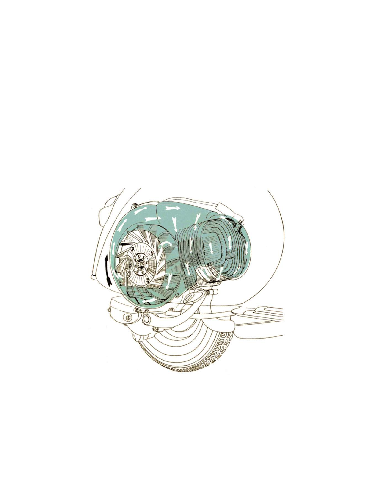
Single horizontal cylinder, two-stroke, with deflector iston and rotary valve, i. e.: fuel
mixture flow to the cylinder is controlled by the rotation of a crankweb (see Fig. 4).
The engine works on a 2% gasoline-oil mixture.
Bore 57 mm (2.24")
Stroke 57 mm (2.24")
Dis lacement 145.45 cc ( 8.88 cu.in )
Com ression ratio 6.8 to 1 .
The engine is ivoted to the chassis of scooter through the cylindrical arm of the
crankcase half, clutch side, rovided with a s indle and two bushes (see Fig. 4). Its
vibrations are dam ed by the rear sus ension with variable rate coil s ring and hydraulic
dam er (see also age 13 ). The rear wheel is secured to the end of the mainshaft.
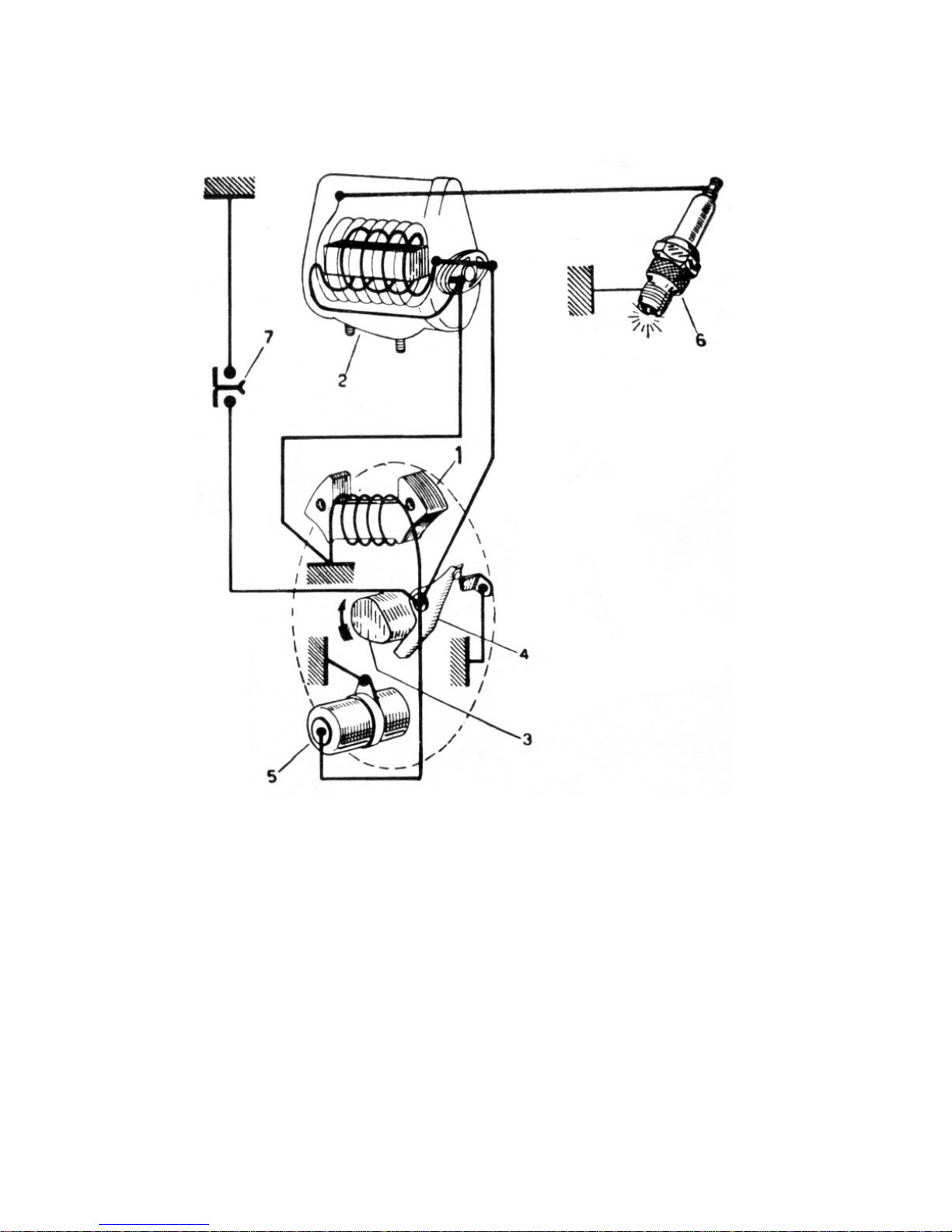
Ignition by an external H. T. coil with rimary winding fed by another coil inside the
flywheel magneto (see Fig. 5).
Sparkplug: Marelli CW 230 A - T or CW 225 N - T, AC 43 F, Cham ion L. 86, Bosch W
225 T 1. - KLG F 70 or F 75.
Ignition timing with s ark advance of 28° ± 10.
Lubrication of iston, cylinder, wrist in, connecting rod, crankshaft, main bearings is
attended to by the oil in the fuel mixture.
Both clutch and gear box o erate in oil bath.
Fuel supply by gravity with gasoline-oil mixture. The carburettor is embodied in the air
cleaner case, has a late-sha ed slide valve and immersed jets.
Fuel tank with total ca acity of 7.7 liters (2.03 USA gals; 1.7 im . gals) and emergency
reserve of about 1.4 I (0.37 USA gals; 0.3 im . gals).
Three way ta («off» - «on» - «reserve»).
Transmission. The engine (see Fig. 4) directly drives the rear wheel through clutch, cush
drive and gear box.
Engine to wheel transmission ratios:
First : 13.35 to 1
Second : 9.32 to 1
Third : 6.64 to 1
Fourth : 4.73 to 1

Fig. 6 - Feeding circuit
1. Fuel cock lever wit sediment trap: A) Reserve, B) Open, C) Closed - 2. Float - 3. Air cleaner wit
carburettor - 4. Air vent for starter device - 5. Set screw for t rottle slide - 6. T rottle slide - 7. Air vent
for main jet - 8. Hole on mixer top - 9. Mixer - 10. Main jet - 11. Idling jet - 12. Air vent for idling jet - 13.
Plug for inlet ole for oil; for laying up. - 14. Idling adjuster - 15. Valve for starter device - 16. Intake
port - 17. Transfer ports - 18. Ex aust duct.
Clutc . Multi late, with linings bonded to the driving discs (see Fig. 4). Control by lever,
on left hand side of handlebars (see Fig. 8), and adjustable cable.
Gear box. 4-s eed drive with mesh gears in oil bath (see Fig. 15). Its adjustable twistgri
control is cou led

with that of the clutch, on left hand side of handlebars (see Fig. 8).
Starting. By means of kick-starter, night hand side of scooter. The multi le gear and
consequently the engine is set in motion through a ratchet sector and a gear by o erating
the kick-starter.
Cooling effected at all engine s eeds by a centrifugal fan (see Fig. 7).
Muffler. Ex ansion and absor tion combined ty e with very high silencing efficiency.
Air cleaner mounted inside the body. Air goes to the carburettor through a large flexible
inlet tube, a silencing chamber and orous filter, which ensures a very quiet air intake.
We recommend not to alter t e muffler or t e air cleaner but to keep t em in perfect efficiency, in
order t at t e noise level does not exceed t e limits (prescribed by law.)

Fig. 8 VESPA controls
1. Gear c ange twistgrip wit clutc control lever - 2. Front brake lever - 3. T rottle control grip - 4.
Lig t and dip switc - 5. Front brake s oes - 6. Rear brake pedal - 7. Kick-starter - 8. Gear s ifter - 9.
Rear brake s oes - 10. Clutc - 11. Carburettor, air cleaner - 12. Starter device control lever - 13. Fuel
tap.
FRAME
Stressed skin body of ressed steel sheet, (see Fig. 1 ), with streamlined, monocoque
ty e structure. It gives full rotection to the driver, to the assenger and to the machine
units; it is com leted in this function by the mudguard and, on the two sides, by the steel
sheet engine bonnet and tool box.
Handlebars in light alloy, with arrangement for head lam and s eedometer. All control
cables and electric wires, connected to the handlebars, are concealed inside them (see
Fig. 8).

Steering column, suspension and w eels. The steering column bears the handlebars,
clam ed on its to end, and the front wheel swinging hub, ivoted at its bottom end
through a stub axle (see Fig. 9).
Front suspension with variable rate coil s ring and double action hydraulic dam er.
Rear suspension: swinging bracket for engine and rear wheel, variable rate coil s ring
and coaxial, double action hydraulic tam er.
- The wheels are interchangeable with rims of pressed steel sheet (0 8").
- Tyres of dia. 3. 0-8".
Saddle of the nose- ivoted, s rung ty e with central s ring adjustable to the driver's
weight.
Brakes. Ex anding ty e with cable control.
Front: lever on R. H. side of handlebars.
Rear: control edal on floorboard, R. H. Drums in light alloy with cooling fins.
Central stand. A two-legged stand, easy to o erate, is arranged under the floorboard. A
strong return s ring in the middle holds it in contact with the floorboard and kee s it from
vibrating while the scooter is being ridden.
Fig. 9 – Engine and suspension
1. Steering column and front suspension – 2. Engine – 3. Pivoting arm of crankcase alf, clutc side –
4. Rear suspension spring and ydraulic s ock absorber

Steering lock. A suitable security lock is arranged on the frame, near the handlebars.
Turning the key anticlockwise and the handlebars to the left, the lock engages the lugs
welded on the steering column, so that the machine can only turn around. Turn the key
clockwise for releasing the steering system (see Fig. 10).
We recommend not to lubricate t e steering lock, even if it does not function properly. Do not attempt
to ride t e mac ine unless t e key is in, and remains in, t e lock and t e andlebars move freely.
Speedometer. The s eedometer is housed in the central ortion of the handlebars (see
Fig. 10) and adds to the a earance of the scooter. It is driven by the front wheel, the flex
drive being com letely enclosed in the steering column. The s eedometer dial is lit during
night riding by a bulb suitably installed in the head lam .
Fig. 10 – Security lock
1. Normal position – 2. closed

Fig. 11 – Handlebar switc
A – Engine cut-out B. Parking lig ts and speedometer bulb on – C. Lig ts off – D. Head lamp, tail lamp
speedometer bulb on – E. Dip switc – F. Horn button - 7. Main switc
Fig. 11A – Cables & arness
1. Flyw eel magneto - 2. External ignition coil - 3. Sparkplug - 4. Low tension terminal - 5. Tail lamp
16V-3W - (. STOP lig t - 6V-3W) - 7. Main switc - 8. Speedometer bulb (6V-0.6W) - 9. Double filament
bulb (6V25/25W) - 10. Pilot lig t 6V-3W - 11. Horn - 12. STOP lig t switc - 13. Inside view of ead lamp
- 14. Black - 15. Red - 16. Grey - 17. Black-yellow - 18. Yellow - 19. W ite - 20. Sky blue - 21. Green - 22.
Violet - 23. Brown.

Fig. 12 – Electric wiring diagram
1. Flyw eel magneto - 2. External ignition coil - 3. Sparkplug - 4. Low tension terminal - 5. Tail lamp
16V-3W - (. STOP lig t - 6V-3W) - 7. Main switc - 8. Speedometer bulb (6V-0.6W) - 9. Double filament
bulb (6V25/25W) - 10. Pilot lig t 6V-3W - 11. Horn - 12. STOP lig t switc - 13. Inside view of ead lamp
- 14. Black - 15. Red - 16. Grey - 17. Black-yellow - 18. Yellow - 19. W ite - 20. Sky blue - 21. Green - 22.
Violet - 23. Brown.
WIRING
The electrical su ly for illumination and horn is in a. c., fed directly from a 6 ole flywheel
magneto (nominal voltage 6V), to the following grou s
The ead lamp, 0 115 mm (4.5"), installed in the handlebars, has a 25/25W double
filament bulb (main and di ed beam), and with a 3 W bulb ( ilot light and arking light).
The tail lamp, with red reflector, has a 3 W bulb which also illuminates the number late
and a 3 W bulb for the STOP light.

Horn
A 0,6 W bulb is rovided for illuminating the s eedometer dial.The light and di switc
unit, with two levers is installed on the right hand side of the handlebars (see Fig. 11 ) ;
one of the control levers has three ositions:
- ilot light, tail lam and s eedometer bulb on;
- lights off;
- head lam , tail lam and s eedometer bulb on;
the other one gives the two lighting conditions of the head lam (main and di ed beam).
The switch has also two ush buttons for cut-out and horn res ectively.
TOOL KIT
1 four-ended box wrench ( 11-14-21-22 mm) ; 2 double o en-ended wrenches ( 11 - 14
and 7-10 mm) ; 1 single o en-ended wrench (8 mm) ; 1 screwdriver. These tools are
contained in a canvas roll which is laced in the left wing together with this booklet and
the test card.
ACCESSORIES
On request the Ves a 150 can be equi ed with following accessories:
Rear saddle of the nose ivoted, s rung ty e, to be secured to three chassis holes after
removing the luggage rack. The central s ring is adjustable to the driver's weight.
A foam rubber pillion seat can be used instead of the rear saddle. The seat can be
secured to the rear luggage rack of the scooter. Both rear saddle and foam rubber seat
are small and attractive looking and give remarkable comfort to the assenger, thus::
com leting the efficiency of sus ension (see Fig. 13).
Spare w eel and bracket. The wheel can be secured in two ways to the scooter:
a. in front, by a light alloy bracket secured to the scooter longeron by means of two
screws.
b. at the rear, by a steel sheet ressing, rovided with s acers, to be clam ed onto the
frame, under the luggage carrier or the rear saddle, by means of the three screws
securing the latter.
A romt re-starting of the scooter after a uncture is made ossible by the s are wheel;
the latter is held by either bracket in such a osition where it is easily accessible and does
not inconvenience the driver at all.

Fig. 13 – Pillion seat, spare w eel and bracket

Owing to the sim le and rational design of the Vespa scooter, no articular ex erience is
required for its o eration, nor skilled ersonnel for its maintenance. The tasks can be
carried out by any customer, even unex erienced, by following some general rules,
O P E R A T I O N
Fuel to be used during and after running-in should be a mixture of gasoline and oil, with
2% ure mineral oil ESSO SAE 30 i. e.: 20 cc of oil er liter of gasoline, or 1/4 int er
11/2 gallon res .
We recommend to use good quality, standard grade car gasoline, and to mix it wit oil t oroug ly.
Keep t e breat er of filler cap clean.
Running-in. Im ortant rules to be followed while running-in 2000 Km (1200 miles)
Do not exceed the following s eeds:
1st gear: 20 Km/h (13 m h)
2nd gear: 30 Km/h (19 m h)
3rd gear: 40 Km/ /h (25 m h)
4th gear: 60 Km/h (37 m h)
- Do not hold these s eeds for long eriods neither use full throttle u -hill.
- Change oil in the gear box and check that nuts and bolts are not slack after the first 1000
Km (600 miles).
- Check that carburettor is well blocked on crankcase to avoid air infiltration.
Starting t e engine. See (Fig. 14) the three ositions of the ta : on, off, reserve.
O en fuel ta , ut gear box in neutral (Fig. 14-15) and the throttle in slow running osition,
then de ress the starting lever.
With cold engine, lift the starter device rod ( lever "C" fig. 14 ). Wit t e t rottle control
twistgrip in the osition of minimum : under these conditions the starter device functions
most efficiently. Do not use the starter device when the engine is warm. When the engine
is running t e lever "C" must be broug t to t e normal position so as to avoid rich
carburation and consequent loss in erformance, increased consum tion etc.
In case of starting troubles due to engine being flooded (unva orized fuel mixture in the
cylinder, and combustion becomes therefore very difficult), roceed according to either
one of following methods.
- Push-start the scooter: engage second gear, de ress the clutch and ush the machine to
a certain s eed; quickly release clutch lever and ull it back as soon as the engine fires.

- Close the fuel ta , remove s ark lug and action the engine by means of the kickstarter;
wi e the lug dry and screw it back. O en the fuel ta and de ress the starting lever.
Exercise care on re-assembling t e sparking plug; start screwing it by and at t e proper angle to
avoid damaging t e cylinder; use t e box wrenc just for t e last turns.
14 - Operations to carry out for starting t e engine
A: open t e fuel cock - B: select "neutral" c C: Pull out t e starter device lever (wit cold engine) - D:
t rottle control grip in idling position c E: depress t e kickstarter.

Fig. 15 - Drive system
I. Gear c ange twistgrip c 2. Clutc control lever c 3. Gear c ange control cables c 4. Gear s ifter c 5.
Selector stem c 5. Selector - 7. 1st gear pinion c 8. 2nd gear pinion c 9. 3rd gear p, )ion c 10. 4t gear
pinion - 11. Mains aft c 12. Cus gear c 13. Clutc .
N. B. - Positions 1-2c3-4 of t e gear c ange twistgrip correspond to 1st 2nd, 3rd and 4t gear
respectively; "0" indicates t e neutral position.
Table of contents
Other VESPA Scooter manuals

VESPA
VESPA LXV 125 Guide

VESPA
VESPA LXV 50 2012 User manual

VESPA
VESPA GTS 250 I.E. Instruction manual

VESPA
VESPA GTV 250 i.e. User manual

VESPA
VESPA LXV 125 ie 2013 User manual

VESPA
VESPA PK 50 User manual

VESPA
VESPA Vespa GTS 250 User manual

VESPA
VESPA GTS 300 HPE User manual

VESPA
VESPA 125 Primavera Guide

VESPA
VESPA Grande User guide

VESPA
VESPA PX 150 USA Instruction manual

VESPA
VESPA LX 50 Instruction manual

VESPA
VESPA LX 4T USA Instruction manual

VESPA
VESPA 946 E4 EMEA 2021 User manual

VESPA
VESPA KT1510 User manual

VESPA
VESPA PRIMAVERA 50 2T 2013 User manual

VESPA
VESPA LX 150 4T USA Instruction manual

VESPA
VESPA LX 50 4T User manual

VESPA
VESPA GTV 125 Guide

VESPA
VESPA ET4 50 Instruction manual