© Vestamatic GmbH
Art.-Nr.: 85301221 E1 • Vestamatic GmbH • Dohrweg 27 • D-41066 Mönchengladbach • www.vestamatic.com
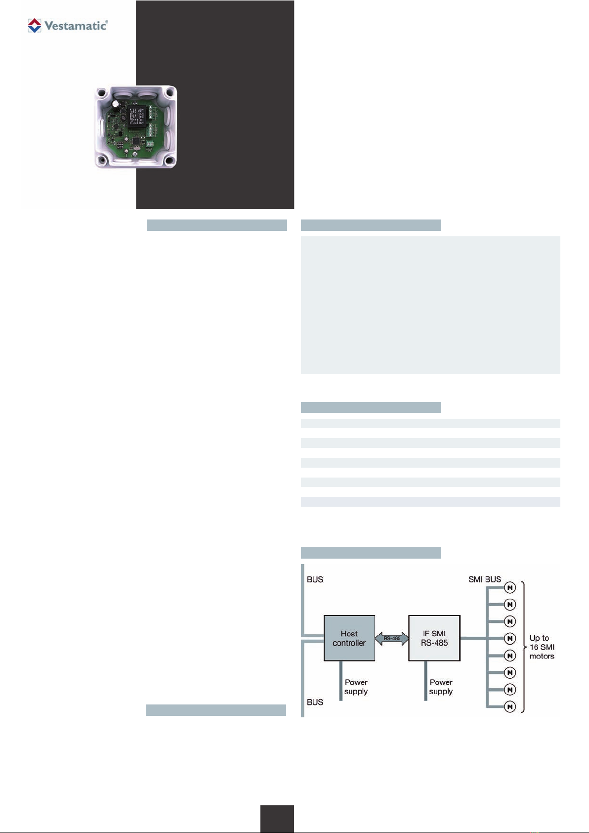
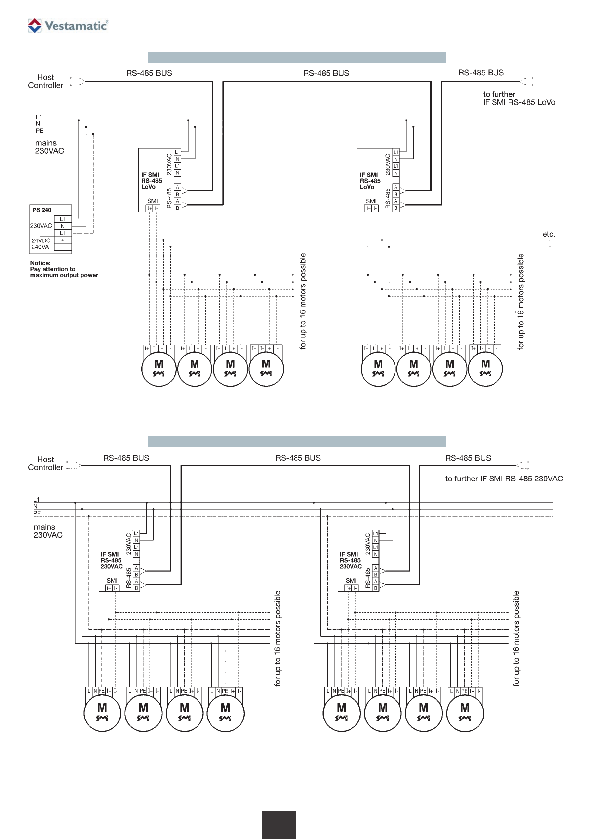
IF SMI RS-485
5.3.6 MSG_SET_POS
This message is used to move all, or a set of sun blind, to an absolute
position.
Message: [SID] / [LEN] / [CMND] / [MSK0] / [MSK1] / [POS0] / [POS1] /
[CRC16]
[MSK0]: LSB of 16-bit mask to select motor address 0..7.
[MSK1]: MSB of 16-bit mask to select motor address 8..16.
[POS0]: LSB of 16-bit absolute position.
[POS1]: MSB of 16-bit absolute position.
The absolute position value is defined as below:
0x0000 is the top position (0%).
0x8000 is the middle position (50%).
0xFFFF is the bottom position (100%).
The IF SMI RS-485 module responds to this request with a general status
message MSG_GETGENSTAT.
The position of each sun blind can be obtained by the detailed response
message MSG_GETDETSTAT.
5.3.7 MSG_SET_TILT
This message is used to move all, or a set of venetian blinds, in a absolute
tilt orientation.
Message: [SID] / [LEN] / [CMND] / [MSK0] / [MSK1] / [TILT] / [CRC16]
[MSK0]: LSB of 16-bit mask to select motor address 0..7.
[MSK1]: MSB of 16-bit mask to select motor address 8..16.
[TILT]: Absolute tilt orientation (0..255).
Absolute tilt orientation is defined as follow:
127 (0x7F) slats completely closed in down direction
0 (0x00) slats completely open (horizontal)
-128 (0x80) slats completely closed in up direction
The IF SMI RS-485 module responds to this request with a general status
message MSG_GETGENSTAT.
The position of each sun blind can be obtained by the detailed response
message MSG_GETDETSTAT.
Remark: The MSG_SET_TILT message uses a manufacturer specific SMI
command, which is currently only supported by Vestamatic
SMI motors.
5.3.8 MSG_SET_POS_STEP_UP
This message is used to move all, or a set of venetian blinds, to an absolute
position combined with an relative up command.
Message: [SID] / [LEN] / [CMND] / [MSK0] / [MSK1] / [POS0] / [POS1] /
[NSTEP] / [CRC16]
[MSK0]: LSB of 16-bit mask to select motor address 0..7.
[MSK1]: MSB of 16-bit mask to select motor address 8..16.
[POS0]: LSB of 16-bit absolute position.
[POS1]: MSB of 16-bit absolute position.
[NSTEP]: Number of steps (1..255) in UP direction. 1 step is defined as
2º rotation of the output shaft of the SMI motor.
The IF SMI RS-485 module responds to this request with a general status
message MSG_GETGENSTAT. The position of each sun blind can be
obtained by the detailed response message MSG_GETDETSTAT.
5.3.9 MSG_SET_POS_STEP_DOWN
This message is used to move all, or a set of venetian blinds, to an absolute
position combined with an relative down command.
Message: [SID] / [LEN] / [CMND] / [MSK0] / [MSK1] / [POS0] / [POS1] /
[NSTEP] / [CRC16]
[MSK0]: LSB of 16-bit mask to select motor address 0..7.
[MSK1]: MSB of 16-bit mask to select motor address 8..16.
[POS0]: LSB of 16-bit absolute position.
[POS1]: MSB of 16-bit absolute position.
[NSTEP]: Number of steps (1..255) in DOWN direction. 1 step is defined
as 2º rotation of the output shaft of the SMI motor.
The IF SMI RS-485 module responds to this request with a general status
message MSG_GETGENSTAT. The position of each sun blind can be
obtained by the detailed response message MSG_GETDETSTAT.
Subject to modifications.
5.3.1 MSG_UP
This message is used to move all, or a set of sun blind, to the top position.
Message: [SID] / [LEN] / [CMND] / [MSK0] / [MSK1] / [CRC16]
[MSK0]: LSB of 16-bit mask to select motor address 0..7.
[MSK1]: MSB of 16-bit mask to select motor address 8..16.
When bit nin mask is set, SMI motor with address nis addressed and
executes a UP command.
The IF SMI RS-485 module responds to this request with a general status
message MSG_GETGENSTAT.
The position of each sun blind can be obtained by the detailed response
message MSG_GETDETSTAT.
5.3.2 MSG_DOWN
This message is used to move all, or a set of sun blind, to the lower position.
Message: [SID] / [LEN] / [CMND] / [MSK0] / [MSK1] / [CRC16]
[MSK0]: LSB of 16-bit mask to select motor address 0..7.
[MSK1]: MSB of 16-bit mask to select motor address 8..16.
When bit nin mask is set, SMI motor with address nis addressed and
executes a DOWN command.
The IF SMI RS-485 module responds to this request with a general status
message MSG_GETGENSTAT.
The position of each sun blind can be obtained by the detailed response
message MSG_GETDETSTAT.
5.3.3 MSG_STOP
This message is used to stop all, or a set of sun blind.
Message: [SID] / [LEN] / [CMND] / [MSK0] / [MSK1] / [CRC16]
[MSK0]: LSB of 16-bit mask to select motor address 0..7.
[MSK1]: MSB of 16-bit mask to select motor address 8..16.
The IF SMI RS-485 module responds to this request with a general status
message MSG_GETGENSTAT.
The position of each sun blind can be obtained by the detailed response
message MSG_GETDETSTAT.
5.3.4 MSG_STEP_UP
This message is used to relatively move all, or a set of sun blind, in UP
direction.
Message: [SID] / [LEN] / [CMND] / [MSK0] / [MSK1] / [NSTEP] / [CRC16]
[MSK0]: LSB of 16-bit mask to select motor address 0..7.
[MSK1]: MSB of 16-bit mask to select motor address 8..16.
[NSTEP]: Number of steps (1..255) in UP direction. 1 step is defined as
2° rotation of the output shaft of the SMI motor.
The IF SMI RS-485 module responds to this request with a general status
message MSG_GETGENSTAT.
The position of each sun blind can be obtained by the detailed response
message MSG_GETDETSTAT.
5.3.5 MSG_STEP_DOWN
This message is used to relatively move all, or a set of sun blind, in DOWN
direction.
Message: [SID] / [LEN] / [CMND] / [MSK0] / [MSK1] / [NSTEP] / [CRC16]
[MSK0]: LSB of 16-bit mask to select motor address 0..7.
[MSK1]: MSB of 16-bit mask to select motor address 8..16.
[NSTEP]: Number of steps (1..255) in DOWN direction. 1 step is defined
as 2° rotation of the output shaft of the SMI motor.
The IF SMI RS-485 module responds to this request with a general status
message MSG_GETGENSTAT.
The position of each sun blind can be obtained by the detailed response
message MSG_GETDETSTAT.
3/ 7
G