TimeLine Lynx Keyboard Control Unit User manual

System Supervisor Unit
09/08/00 3-1
Installation
Introduction
This chapter describes installation and interface procedures for
the Lynx System Supervisor Unit (SSU). It also includes a quick
initialization check, to verify that the SSU is communicating
properly.
As the SSU offers almost no operational features on its own, this
chapter will concentrate on installations utilizing various
TimeLine and other manufacturers equipment.
Part I of this chapter describes SSU installation logistics. Part II
describes SSU installation with TimeLine controllers, Lynx
Modules, and console automation computers. The interface dia-
grams in Part II of this chapter will also help you determine the
appropriate configuration. Part III is an SSU communications
check procedure.
These procedures assume that you know the optimum system con-
figuration for your facility, or that you have studied the applica-
tions chapter of this manual.
System Setup Planning
Before you install and configure your equipment, there are several
fundamental issues to consider
AC Power
An AC outlet is required for the SSU. If there is more than one
piece of equipment in the rack, use a surge-protected power
distribution strip, fitted with an adequate extension cable.
Each SSU comes with a 3-wire, IEC power cable. The SSU is
fitted with an internally fused power supply, which operates
without adjustment over a wide range of conditions: 90-265 VAC,
50-60 Hz.

Installation
System Supervisor Unit
3-209/08/00
Power On Initialization
As there are no operational parameters that can be selected on the
SSU, without an external controller connected (e.g., KCU or CCU),
only a few checks can be performed with the SSU alone.
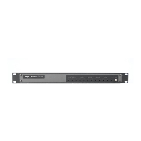
On power-up, the SSU will illuminate every switch and LED ex-
cept for XMT DATA and RCV DATA. After a short time the lights
will extinguish EXCEPT for the PROC 1, 2, and 3 LEDs, and the
EXT VID light, which will flash.
As equipment is connected to the SSU, certain LEDs will turn on
to verify communication to that device. For example: If Lynx-2
modules are daisy-chained to the SSU, via their 9-pin RS422 con-
nector to TRIB PORT 1, the TRIB PORT LED will illuminate on
the front panel.
Part I - Installation
Rack Mount Installation
The SSU conforms with industry standard dimensions, for 2U
rack installation. Each SSU is supplied fitted with two rack
“ears”. To install the SSU in the rack, you will need a Phillips
screwdriver.
1. Slide the SSU into position in the equipment rack.
2. Secure by inserting two, #8-32 rack screws through each ear
and into the threaded rack rail, then tightening.
3. Attach a power cable to the SSU.

Installation
System Supervisor Unit
09/08/00 3-3
Cabling
The SSU requires both equipment specific and generic cabling.
Figure 3-1. Cabling
Lynx-2 Cabling
Use the 9-pin to 9-pin RS422 cable supplied with the SSU, to con-
nect the first Lynx-2 Time Code Module to the SSU TRIB PORT 1.
Use the short 9-pin to 9-pin RS422 cables, supplied with each
Lynx-2 module, to daisy chain the modules together.

Installation
System Supervisor Unit
3-409/08/00
Keyboard/Computer Control Cabling
Use a 9-pin to 25-pin ‘D’ cable to connect the CCU to the SSU
Keyboard/Computer Control Port. Use a 15-pin to 25-pin ‘D’ cable
to connect the KCU to the SSU Keyboard/Computer Control Port.
Note:
If only one TimeLine controller is being used, connect to
Keyboard/Control Port 1.
Remote Motion Controller Cabling
Use a 50-pin ‘D’ to 50-pin ‘D’ cable to connect the RMC to the SSU
Logic I/O connector.
Time Code Cabling
Use the supplied 37-pin D connector to connect the appropriate
time code generator outputs from the SSU Audio I/O connector.
Refer to the Appendix for pin-out and connector specifications.
Generic Cabling
Use standard BNC cables to connect the SSU to external video
sync sources. The VID REF BNC jacks are wired in parallel and
can be used to loop from the SSU to other equipment.
Use a standard 5-pin MIDI connector to connect to the MIDI time
code output.

Installation
System Supervisor Unit
09/08/00 3-5
Basic Interface Connections
Specific cable installation is application dependent. If needed,
please refer to Part II of this chapter for help in determining your
cabling requirements.
Basic interface requires a minimum of three connections:
•Connect a video reference source.
•Connect a RS422 communications cable to the Lynx-2 modules.
•Connect a Keyboard Serial communication cable from an
external TimeLine Controller.
Video Reference Source
The video reference source should be either NTSC or PAL black-
burst, color bars, or composite sync, and should come from a
reliable reference sync generator or house sync generator. The
reference source should be properly terminated.
Figure 3-2. Video Reference Source Connection
Connect the video reference source to the VID REF BNC connector
on the back of the SSU. There are two parallel BNC input jacks
on the SSU. Connect all other equipment requiring the video ref-
erence by looping through the SSU.

Installation
System Supervisor Unit
3-609/08/00
Lynx RS422 Input
Connect a 9-pin to 9-pin RS422 cable from the first Lynx module
in the Lynx daisy-chain to the SSU TRIB PORT 1 connector. It is
important to connect to TRIB PORT 1, since the other Trib Ports
do not accept Lynx serial communication.
Figure 3-3. RS422 Trib Port
TimeLine Controller Inputs
If you are using a CCU, connect the 9-pin ‘D’ connector of the 9-pin
to 25-pin ‘D’ cable into P1 on the CCU Processor Board, and the
25-pin end into the SSU Keyboard/Computer Control Port 1.
If you are using a KCU, connect the 15-pin end of the 15-pin to
25-pin ‘D’ cable to the KCU power supply GPI/Supervisor connec-
tor. Connect the 25-pin end to the SSU Keyboard/Computer
Control Port 1.
Note:
If you wish to use two Controllers simultaneously, it does not matter
which Controller is connected to Port 1 or 2. If, however, you are
connecting a single Controller, use Port #1.

Installation
System Supervisor Unit
09/08/00 3-7
Figure 3-4. CCU and KCU Connections to SSU
Audio I/O Connections
This connection provides three time code generator outputs,
generator pilot output, pilot input, and an ADR beep output.
TimeLine does not make a pre-made cable for these connections,
but does provide a connector that can be wired to your
requirements.
Figure 3-5. Audio I/O Connector

Installation
System Supervisor Unit
3-809/08/00
Logic I/O Connections
This connection provides eight GPI relay outputs, five annunciator
outputs, ADR beep outputs, and switch closures and tallies for
Play, Fast Forward, Rewind, Record, Stop, Loop, Rehearse and
Edit. This is the connection used for the optional Remote Motion
Controller, as well as user definable options.
Figure 3-6. Logic I/O Connector
Power Out Connections
The Power Out connector can be used to power auxiliary switches
or lamps, or other user devices. External power usage should be
limited to two amperes maximum from the +5 volt supply, and to
100 milliamperes each from the +12 and -12 volt supply.
Figure 3-7. Power Out Connector

Installation
System Supervisor Unit
09/08/00 3-9
Part II - Interface Diagrams
This section presents a variety of interface diagrams. Refer to the
diagram that most closely represents your system setup and appli-
cation. Slight differences in equipment may require small configu-
ration modifications.
Figure 3-8. SSU to CCU and Lynx

Installation
System Supervisor Unit
3-10 09/08/00
Figure 3-9. SSU to KCU and Lynx
Figure 3-10. SSU to KCU/CCU, RMC and Lynx

Installation
System Supervisor Unit
09/08/00 3-11
Part III - Communications Check Procedure
Serial communications between each piece of equipment connected
to the SSU, can be continued by checking the diagnostic LEDs for
each port. The following is a check list of these procedures to help
verify correct installation.
Trib Port
Verify the RS422 Trib Port 1 communication, with the Lynx-2
Time Code Modules, by performing the following:
1. Press the [SELECT] key so it illuminates.
2. Turn the [SELECT] Knob until the Trib LED lights.
3. Press the [AUX/SELECT] key so it illuminates. The [SELECT]
key will go off.
4. Turn the [SELECT] Knob until the number 1, for Trib Port #1,
shows in the display.
Verify the following:
•The XMT and RCV Data LEDs flicker, or are on solid.
•The Diag On LED is on solid.
•The MSG OK LED is on solid.
Control Port 1 and Control Port 2
Verify Control Port 1 and 2 communications with the controllers
by performing the following:
1. Press the [SELECT] key so it illuminates.
2. Turn the [SELECT] Knob until the Ctrl Port 1 LED lights.
Verify the following:
•The XMT and RCV Data LEDs will flicker, or are on solid.
•The Diag On LED is on solid.
•The MSG OK LED is on solid.
3. Turn the [SELECT] knob until the CTRL PORT 2 LED lights,
and verify the diagnostic LEDs are on for Control Port #1.

Installation
System Supervisor Unit
3-12 09/08/00
Other manuals for Lynx Keyboard Control Unit
1
Other TimeLine Recording Equipment manuals
TimeLine
TimeLine Micro Lynx ACG-1 Option Card User manual
TimeLine
TimeLine Micro Lynx VITC Option Card User manual
TimeLine
TimeLine Micro Lynx M3 Option Card User manual
TimeLine
TimeLine Micro Lynx VSG Option Card User manual
TimeLine
TimeLine Micro Lynx System Unit User manual

TimeLine
TimeLine Micro Lynx M3 Option Card User manual
TimeLine
TimeLine Micro Lynx ACG Option Card User manual

TimeLine
TimeLine Micro Lynx VITC Option Card User manual
