VESTEL EVC02 User manual

ELECTRIC VEHICLE CHARGER TESTER T2
User Manual
Kullanım Kılavuzu

English - PB English - 1
CAUTION
RISK OF ELECTRIC SHOCK
CAUTION: VESTEL ELECTRIC VEHICLE CHARGER DEVICE SHALL BE MOUNTED BY A LICENSED OR AN EXPERIENCED
ELECTRICIAN AS PER ANY REGIONAL OR NATIONAL ELECTRIC REGULATIONS AND STANDARDS IN EFFECT.
EVC TESTER KIT INCLUDES
1. Testing Apparatus for Type-2 socket outlet
2. USB Type C to Type A OTG Cable
3. Console Cable
4. User Manual
REQUIRED ITEMS FOR INSTALLATION FOR EVC02
1. Vestel EV Charging Station
2. Vestel EVC Tester and USB / Console cables
3. Android smartphone with OTG support and Vestel EVC configurator application installed (Google Play
Store)
Be sure that all switches on EVC tester is off position before starting test.

English - 2
REQUIRED ITEMS FOR INSTALLATION FOR EVC04
1. Vestel EV Charging Station
2. Vestel EVC Tester and USB / Console cables
3. Android smartphone with OTG support and Vestel EVC configurator application installed (Google Play
Store)
Be sure that all switches on EVC tester is off position before starting test.
EVC TESTER USAGE DURING INSTALLATION for EVC02
Please follow the steps in the installation guideline provided in the product package. Before turning on the
power to the EV Charger, Connect console cable of the EVC tester to the console port of the EV Charger as
shown in figure.1.
Figure.1
1. Console cable is connected to the console port of the EV Charger.
2. Console connection should be done to an isolated source.
3. The connection in primer part can done by authorized service person.

English - 2 English - 3
EVC TESTER USAGE DURING INSTALLATION for EVC04
Please follow the steps in the installation guideline provided in the product package. Before turning on the
power to the EV Charger, Connect console cable of the EVC tester to the console port of the EV Charger as
shown in figure.2.
Figure.2
1. Console cable is connected to the console port of the EV Charger.
2. Console connection should be done to an isolated source.
3. The connection in primer part can done by authorized service person.
WARNING
• Tester should be used in EVC device which has suitable MCB connection in line.
• L1,L2,L3,N sockets should only be used for voltage controls. External load connection should not be done.
• Tester should be used by an authorized service person.

English - 4
EVC CONFIGURATOR APPLICATION USAGE
Connect EVC tester USB port to the smartphone USB input by using USB OTG cables as shown in figure.3
After connecting EVC Tester to the phone, Android operating system
will request permissions.
The permissions required by the Android
operating system should be accepted.
Open VESTEL EVC configurator application on Android phone. Follow below steps for installation.
=> User Manual
=> E-mail Options menu.
If the phone language is a language other than Tur-
kish, the application language will be automatically
English.
Figure.3

English - 4 English - 5
Throught E-Mail Settings, the E-Mail
Address setting screen is displayed
and the e-mail address is set where
the log files will be sent.
Please click menu icon first. In the menu, please click on Home-
page button.
Please click the “Connect“ button. After comleting device connections, console port
logs will be shown on the terminal screen. After
comleting device connections, console port logs
will be shown on the terminal screen. “Get Serial
No” button is used to see the serial number of the
device for EVC02. This function of the tester are not
supported for EVC04.

English - 6
For EVC04 model charging stations, the log opens automatically when connection is made between
the tester and the charging stations. For sharing these logs, the “Send Email” button under the
heading “EV CHARGER STATUS CONTROL” can be used. Other functions of the tester are not sup-
ported for the EVC04 model.
INSTALLATION POWER SETTINGS
- Throught the drop down menu in Power Settings Page, the ins-
tallation current level and number of phases can be selected.
- After selecting the current level and number of phases, press
“Set“ button and the lastest setting reply from EV charger is
shown on the terminal Screen.
- Press ”Check Current” button. The set power rate will be
shown on terminal screen.
- Press “Get Phase Info“ button. The set number of will be
shown on the terminal screen.

English - 6 English - 7
CONNECTIVITY SETTINGS
- Press “Set URL“
button and enter
URL on the displa-
yed page and press
“Set“ button.
- Press “Set PIN“
button and enter
PIN on the displa-
yed page and press
“Set“ button.
- Press “Set APN“
button and enter
APN on the displayed
page and press “Set“
button.
To check the URL,
PIN and APN infor-
mation,
press
“Check URL“,
“Check PIN“,
“Check APN“,
buttons.
- Press “Set APN
User“ button and
enter user info on
the displayed page
and press “Set“
button.
- Press “Set APN
Password“ button
and enter password
on the displayed
page and press
“Set“ button.
“Set PIN“, “Set APN User“ and “Set APN Password“ settings are optional based on the SIM card which is
used during installation.

English - 8
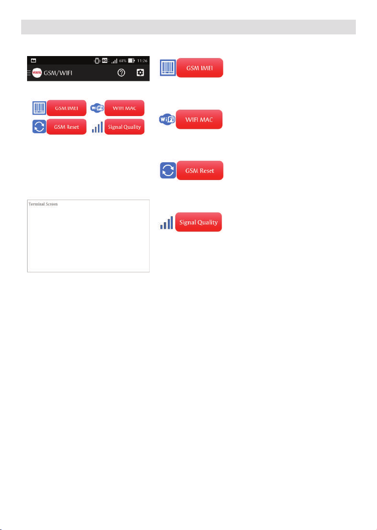
GSM / WIFI GENERAL CONTROLS
To display the IMEI number on EVC models with GSM Modules,
press “GSM IMEI“ button.
To display the MAC address on EVC models with WIFI modules,
press “WIFI MAC“ button.
To reset the GSM module on EVC models with GSM modules,
press “GSM RESET“ button.
To display the Signal Quality, press “Signal Quality“ button. The
signal quality display may be ON/OFF.
In this mode EV charger only measures signal level and prints
it on terminal screen. Signal quality mode must be disabled to
connect the EV charger to an OCCP central system.
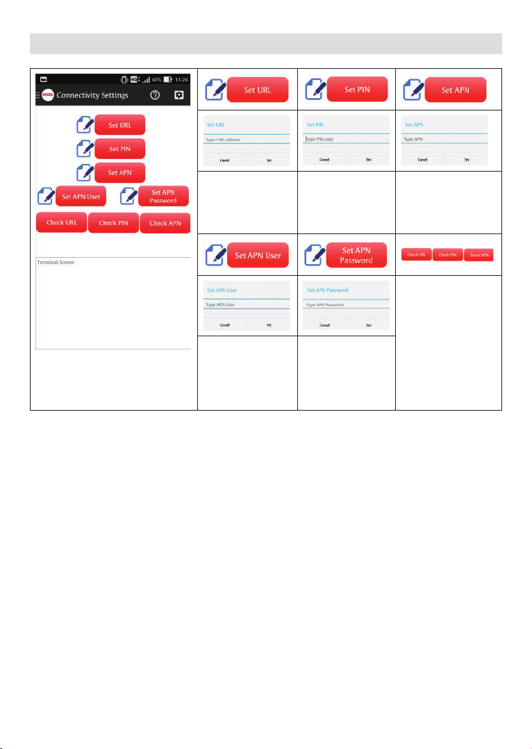
If your EVC models is EVC02-AC*U** and supports cellular connectivity, you should check GSM signal quality
level before the installation of the unit. Switch to “GSM / WIFI“ page from menu and click the “Signal Quality”
icon (If your SIM card has PIN code, you need to configure PIN code first from “Connectivity Settings“ page).
EV charger will change its operation mode to GSM signal measurement. The signal level will be printed on the
terminal screen continously. GSM / 3G connection quality will vary based on the operator grid coverage area.
The device direction and placement must be completed where the signal quality is best.
• If the signal quality is between 0-14, the signal is not powerful enough to establish connection.
• If the signal quality is between 14-22, the signal is at medium level and you can configure your charging
station.
• If the signal quality is between 22-31, the signal is at high level.
After checking signal quality, click the “Signal Quality” button again to shutdown signal quality check mode and
switch the EVC to the normal operation mode. New cellular connectivity settings must be completed for proper
operation. Switch to the “Connectivity Settings“ page from menu.

English - 8 English - 9
EV CHARGER HEALTH CHECK
You can turn on console logs bu pressing “Log On“ button.
Be sure to turn off the logs from “Log OFF“ button before
leaving the charging station after commissioning.
To turn on the OCCP logs, please press “OCPP Log On“ button.
Be sure to turn off the OCPP logs from “OCPP Log OFF“ button
before leaving the charging station after commissioning.
Please be sure that to activate Info Errors and send
email buttons OCPP Log On should be selected.
To display the total charging time, the total consumed power
and charge count of the charging station, press “Info“ b
To display the logged errors of the charging station, press
“Errors“ button.
To send the data complied in the terminal display to the e-mail
address set in the “Settings“ menu, press “Send Logs“ button.
Abbreviations
PS : Meaning of Ps is pilot state and value of PS changes according to EVC CP voltage.
A1 : Pilot State Unplugged - No Cable
A2 : Pilot State Unplugged PWM
B1 : Pilot State Unplugged in - Vehicle connected
B2 : Pilot State Ready - Vehicle connected and ready to charge
C1 : Pilot State EV Ready - Vehicle connected and ready to charge
C2 : Pilot State Charging - Charging
D1-D2 : Pilot State Ventilation
EE - Error State
E : This output describes the error of EVC. All errors have a special number and error number can be matched
from list below. You can check troubleshooting section for solving the error conditions.
0: No Error
1: PowerOutageOrShortError
2: PilotDiodeError
3: UndefinedStateError
4: UndefinedCableCurrentError
5: ContactorWelded

English - 10
6: ContactorDoesNotResponse
7: TemperatureError
8: ProximityPilotConnectionError
9: InterlockUnlockError
10: InterlockLockError
11: RtcCurrentError
13: ProximityPilotResistanceChangeError
14: RFIDConnectionError
15: UnavailableEVError
16: OverCurrentPhase1Fault
17: OverCurrentPhase2Fault
18: OverCurrentPhase3Fault
19: OverVoltagePhase1Fault
20: OverVoltagePhase2Fault
21: OverVoltagePhase3Fault
22: UnderVoltagePhase1Fault
23: UnderVoltagePhase2Fault
24: UnderVoltagePhase3Fault
M : Value of M shows mode of EVC.
0:MODE_NOT_CONNECTED
1:MODE_PAUSED
2:MODE_CHARGING
3:MODE_CHARGING_COMPLETED
4:MODE_CHARGING_STOPPED
5:MODE_READY
6:MODE_WAITING_FOR_ECOTIME
7:MODE_STOPPED_DUE_TO_ECOTIME
8:MODE_ERROR

English - 10 English - 11
USING THE HAND TERMINAL
-When PE and B switches are activated the Ground line, Charger-Cable, Charger-Vehicle connections estab-
lished.
-Have one of 13A, 20A, 32A and 63A cable type activated and then activate the C switch to simulate Charging.
-If D switch is activated the Ventilation can be simulated. If activated off charging. during Charging, the device
will turn
Measurement point for
L3 signal
Measurement point for
L2 signal
Measurement point for
L1 signal
Measurement point for
CP signal
Measurement point for
PROTECTIVE EARTH
Singal
Measurement point for
NEUTRAL Singal
PE (ON)
Earth line Connection C (ON)
Unit ready charge.
B (ON)
Charging Cable Connected
to the vehicle
Charge current adjust-
ment switches. Have only
one of these switches ON.

English - 12
MEASUREMENT SPECIFICATIONS
Voltage Measurements
Display Range 0.0V - 300V AC
Measurement Range 0.0V - 300V AC
Frequency Range 45Hz - 65Hz
Control Pilot PWM Measurements
Voltage Range ± 14V DC
Voltage Resolution 0.1V
Frequency Range 940Hz - 1 040Hz
Frequency Resolution 1Hz
Duty Cyde Range 2% - 98%
Response Time Range 1ms - 10s
Resolution 1ms
According to IEC61851-1, when B switch is in Turn ON position and C Switch is in Turn OFF position, “Charge is
not requested” from EVSE, Pilot State B. The scope measurement of the CP signal can be measured through
measurement point. In Pilot State B, CP signal should be visible on the oscilloscope. The positive portion of the
signal should be approximately +9V, which indicates charge has not been requested by EV and scope output
should be like below figure.

English - 12 English - 13
According to IEC61851-1, when both B and C switches are in Turn ON position, “Charge is requested” from
EVSE, Pilot State C. The scope measurement of the CP signal can be measured through measurement point.
In Pilot State C, CP signal should be visible on the oscilloscope. The positive portion of the signal should be ap-
proximately +6V, which indicates charge has been requested by EV and scope output should be like below figure.
According to IEC61851-1, when B, C and D switches are in Turn ON position, “Charge is requested” from EVSE
with ventilation requirement, Pilot State D. The scope measurement of the CP signal can be measured through
measurement point. In Pilot State D, CP signal should be visible on the oscilloscope. The positive portion of the
signal should be approximately +3V, which indicates charge and ventilation have been requested by EV.

English - 14
Charging Mode
ATTENTION: The unit can be tested for cables with different current rates by turning only one of the current
switches ON and turning OFF the other switches.
Electric Vehicles that Require Ventilation during Charging
WARNING
For some vehicles the battery systems include hazardous gases and the vehicle is charged in an enclosed
space, the environment shall be ventilated.
EVC02-AC and EVC04-AC series charging station is only for charging vehicles that does not require
ventilation during charging.
PE (ON) C (ON)
B (ON)
Only One of the current
buttons is ON

English - 14 English - 15
Charging Mode with Ventilation
PE (ON)
C (ON)
D (ON)
B (ON)
Only One of the current
buttons is ON
Caution : Charge should stop when the
D button is ON while the charger is an
charging mode.

Türkçe - PB Türkçe - 1
DİKKAT
ELEKTRİK ÇARPMASI RİSKİ
DİKKAT: VESTEL EV ŞARJ CİHAZI MONTAJININ YÜRÜRLÜKTEKİ TÜM BÖLGESEL VE ULUSAL ELEKTRİK YÖNETMELİKLERİ VE STAN-
DARTLARINA UYGUN BİÇİMDE SADECE LİSANSLI VE DENEYİMLİ BİR ELEKTRİKÇİ TARAFINDAN YAPILMASI GEREKLİDİR.
EVC TEST CİHAZI KİTİ ŞUNLARDAN OLUŞUR
1. Tip 2 priz için Test Düzeneği
2. USB Tip C- Tip A OTG Kablosu
3. USB Tip B (Mikro USB) - Tip A OTG Kablosu
4. Konsol Kablosu
5. Kullanım Kılavuzu
EVC02 MONTAJI İÇİN GEREKLİ ALETLER
1. Vestel Elektrikli Araç Şarj İstasyonu
2. Vestel EVC Test Cihazı ve USB / Consol Kabloları
3. Vestel EVC Konfigüratör kurulu OTG destekli android telefon (Google Play Mağazası)
Teste başlamadan önce EVC test cihazının tüm düğmelerinin kapalı olduğundan emin olun.

Türkçe - 2
EVC04 MONTAJI İÇİN GEREKLİ ALETLER
1. Vestel Elektrikli Araç Şarj İstasyonu
2. Vestel EVC Test Cihazı ve USB / Consol Kabloları
3. Vestel EVC Konfigüratör kurulu OTG destekli android telefon (Google Play Mağazası)
Teste başlamadan önce EVC test cihazının tüm düğmelerinin kapalı olduğundan emin olun.
EVC02 MONTAJ SIRASINDA EVC TEST CİHAZININ KULLANIMI
Lütfen ürün paketinde belirtilen kurulum kılavuzundaki adımları takip edin. EV şarj cihazını açmadan önce EVC
test cihazının konsol kablosunu EV şarj cihazına şekil.1’deki gibi bağlayın.
Şekil.1
1. Konsol kablosu Elektrikli Araç Şarj cihazının konsol bağlantı noktasına bağlanır.
2. Konsol izole bir kaynağa bağlanmalıdır.
3. Primer parçasında bağlantı yetkili servis personeli tarafından gerçekleştirilmelidir.

Türkçe - 2 Türkçe - 3
EVC04 MONTAJ SIRASINDA EVC TEST CİHAZININ KULLANIMI
Lütfen ürün paketinde belirtilen kurulum kılavuzundaki adımları takip edin. EV şarj cihazını açmadan önce EVC
test cihazının konsol kablosunu EV şarj cihazına şekil.2’deki gibi bağlayın.
Şekil.2
1. Konsol kablosu Elektrikli Araç Şarj cihazının konsol bağlantı noktasına bağlanır.
2. Konsol izole bir kaynağa bağlanmalıdır.
3. Primer parçasında bağlantı yetkili servis personeli tarafından gerçekleştirilmelidir.
UYARI
• Test cihazı uygun hat içi MCB bağlantısına sahip EVC cihazı içinde kullanılmalıdır.
• L1,L2,L3,N soketleri sadece gerilim kontrolleri için kullanılmalıdır. Harici yük bağlantısı yapılmamalıdır.
• Test cihazı yetkili servis personeli tarafından kullanılmalıdır.

Türkçe - 4
EVC KONFİGÜRATÖR UYGULAMASININ KULLANIMI
EVC test cihazını şekil.3 ‘ te gösterildiği gibi USB OTG kabloları kullanarak EVC test cihazı USB bağlantı noktasından
akıllı USB girişine bağlayın.
EVC test cihazını telefona bağladıktan sonra Android işletim sistemi
izinler isteyecektir.
Android işletim sisteminin istediği izinler
kabul edilmelidir.
Android telefonda VESTEL EVC konfigüratör uygulamasını açın. Kurulum için aşağıdaki adımları
takip edin.
=> Kullanım Kılavuzu
=> E-Posta seçenekleri menü
Telefon dili Türkçe hariç bir dil olursa uygulama dili
otomatik olarak İngilizce gelecektir.
Şekil.3
Table of contents
Languages: