Vetek TI-1200 User manual

Manual page 1
Hantverksvägen 15, 76493 Väddö - Sweden
Tel: +46176-208920, [email protected], www.vetek.com
COMPLETE MANUAL
WEIGHING INDICATOR TI-1200 and TI-1200-S
TI-1200 with rechargeable battery.
TI-1200-S without rechargeable battery and with a smaller cabinet.
Note: When TI-1200 is shipped as a part of a complete Scale e.g. AV-250-seies and AL-100-21, the Scales are normally
calibrated. When TI-1200 is shipped together with Loadcells it is adjusted to the application but a calibration is always needed at
the place of installation.
EC type-approved non-automatic weighing instrument Number FI 01.1.04
Accuracy class
Manual_TI-1200_V1

Manual page 2
TABLE OF CONTENTS Page
INTRODUCTION TO THE TI-1200 DIGITAL INDICATOR 2
INSTALLATION TI-1200 3
INSTALLATION TI-1200-S 4
CONFIGURATION 6
CALIBRATION 11
SPECIFICATIONS 13
SERIAL PORT INFORMATION 14
DISPLAYED ERROR CODES AND FAULT LOCALIZATION 16
OPERATION 17
INTRODUCTION TO THE TI-1200 DIGITAL INDICATOR
TI-1200 Digital Indicator is a general purpose, industrial grade weight indicator.
TI-1200 comes with an internal 6V rechargeable battery, are capable of driving four 350 ohm load cells and operate identically. All readout up
to 50,000 display divisions on a liquid crystal display (LCD) with back light. All set up parameters may be entered via the front panel keys,
including calibration.
An external power supply is included. The external power supply functions (9 VDC) as a charger* for the rechargeable battery. The power
supply may also be used as the main power supply.
TEST CERTIFICATE: Number FIT 01.I.02 class
TI-1200 has 2 menues for configuration:
-Setup (“F”) which configure the Indicator to your weighing application.
-User (“A”) which configure the Indicator to the serial communication.
*Models:
TI-1200 : With rechargeable battery. Supply 9 VDC.
TI-1200-S : Without rechargeable battery. Supply 9 VDC. Smaller cabinet

Manual page 3
INSTALLATION TI-1200 (with battery)
J1
S+E+ S-
E-
P-
J2
P+ JP4
J3
TXD
RXD
GND
P-
nc
nc
Main board layout.
Note: Don’t forget to connect the cable from calibration switch to JP4 when mounting the back.
The cable from calibration
switch can be removed
during installation
When installing the back
has to be removed. Could
be mounted like this
during installation.
For some applications is
the charger board
disconnected and the
power is connected direct
to J2.
In this case the battery
normally is removed.
If you want it is possible to demount
the contact and connect the cable direct
to battery charger or J2.
Note: +centre contact
The cable from the Loadcell (s)
should be connected to J1.
Remove a sufficient part of the
external isolation to avoid strength
on the wires.
Colours, se next page.
Connect the shield to E-
Calibration
N
ormal
+ -
+ -
+
-
Supply
9 VDC
To 6 V battery
To J2
Display PCB
Charger PCB
Automatic start: Short transistor
Q1 between above two points.

Manual page 4
INSTALLATION TI-1200-S (without battery)
J1
S+E+ S-
E-
P-
J2
P+ JP4
J3
TXD
RXD
GND
P-
nc
nc
If you want it is possible to demount the contact and connect the
cable direct to battery charger or J2.
Note: +centre contact
Calibration
N
ormal
The cable from the Loadcell (s)
should be connected to J1.
Remove a sufficient part of the
external isolation to avoid
strength on the wires.
Colours, se next page.
Connect the shield to E-
Display PCB
Calibration switch
Automatic start: Automatic start:
Short transistor Q1 between above
two
p
oints.

Manual page 5
CONNECTING THE WEIGH PLATFORM / LOADCELL (s)
Connect your shielded load cell cable to terminal J1 on the main board.
+ Excitation
(Power to
Loadcell)
E+
+ Signal
Input
S+
- Excitation
(Power to
Loadcell)
E-
- Signal
Input
S-
CONNECTING THE SERIAL PRINTER, REMOTE DISPLAY OR COMPUTER
The TI-1200 indicator comes standard with one full duplex RS-232 serial port, designed for connection to either a PC or a serial printer. The
same port may be also used as a simplex, RS-232 port designed for connection to a remote display.
Connect your serial printer, remote display or computer communication cable (not included) to terminal J3 on the main board.
J3
GND
RXD
TXD
nc
nc
Figure 2-3: Connection assignments for the serial communication terminal
Terminal J1
Loadcell
+ Input
+ Output
- Input
- Output
Loadcell
+ Input
+ Output
- Input
- Output
If more than one
Loadcells, all should be
connected parallel.
355 SB2 AKA AG 1042
Blue Red Red Brown Green
White Green White Yellow Red
Black White Black Green Black
Red Black Yellow White White
E-, Cabinet or GND J3
If S-Loadcells in tension the S+ and
S- has to be shifted.

Manual page 6
CONFIGURATION
OVERVIEW
The indicator contains two main setup menus: The Setup (“F”) menu which configures the indicator to your weigh platform and the User (“A”)
menu which configures the serial communication port and enables some user options. The Setup and User menus consist of several menu selections,
each with its own sub-menu of choices.
To set up the indicator, you must first enter the appropriate menu mode. Once there, four of the front panel keys become directional navigators to move around in the
menus, and one key is used to save or SET the selections.
ENTERING THE SETUP MENU
1. Power off the indicator by ZERO/OFF in 3 secunds or by unplugging the power source
2. Set calibration switch in calibration mode (right position).
3. Power on the indicator by ON/PRINT or by plugging in the power source. The indicator shows ” F 1” to indicate that you are in Setup
Menu mode.
NAVIGATING IN THE SETUP MENU
1. Use the directional keys shown in the Figure to move around in the Setup Menu Chart.
2. To move to the selection level, press ZERO/OFF (down) key once. The current saved selection is shown.
3. To move to a new “F” heading, use TARE (left) or ON/PRINT (right) key to move right or left in the Setup Menu Chart.
4. If you want to go back whithout saving press lb/kg.
5. If a digit flashing, use lb/kg and ZERO/OFF for choosing value.
6. To save a new selection, press the NET/GROSS (Set) key .To exit without saving, press the PRINT (up) key to return to the current “F”
heading.
7. You can cancel calibration anytime with switching back to normal mode. An alternative is to disconnect the power.
F1
Grads
F2
Span Gn.
F4
Zero Range
F5
Mot. Band
F6
Dig. Filter
F7
Ovld. Limit
25 50 75 100 150 200 1248
100% 1.9%
1d 3d 5d 10d
F8
Calib. Unit
F9
Dsp. Div.
lb kg
500 1000 1500 2000 2500 3000 4000 5000 6000 8000 10000 12000 20000 30000 40000 50000
0.5d 1d 3d0d 5d
F3
Zero Band
0d 2% 1d 9d
125
F10
Dec. Pt.
F17
Span Calib.
Press ZERO
key to begin
F18
Cal. View
Press ZERO
key to begin
F19
Key-in Zero
Press ZERO
key to begin
F20
Key-in Span
Press ZERO
key to begin
0 0.0 0.00 0.000 0.0000 00
F16
Zero Calib.
Press ZERO
key to begin
2%
0.25d
There is an F21 sub-menu present that is for FACTORY USE ONLY!
The User (“A”) menu sub-menus appear when scrolling left or right from the “F” menu.

Manual page 7
SETUP MENU DESCRIPTIONS AND PROCEDURES
Factory-set defaults are shown in bold.
NAME/CODE DESCRIPTION CODE/VALUE
F1
Graduations
Specifies number of full-scale graduations. Value should be consistent with legal
requirements and environmental limits on the useful system resolution.
500 1,000 1,500 2,000
2,500 3,000 4,000 5,000
6,000 8,000 10,000 12,000
20,000 30,000 40,000 50,000
F2
Span Gain
Span Gain is related to A/D integration time. The larger the span gain, the higher the
internal resolution, but the slower the update speed. Note that the scale must be re-
calibrated whenever this parameter is altered. See Appendix C for more information.
25 50
75 100
150 200
F3
Zero Track Band
Selects the range within which the scale will automatically zero. Note that the scale
must be in standstill to automatically zero. Selections are in Display Divisions.
0d 0.5d 1d 3d 5d
F4
Zero Range
Selects the range within which the scale may be zeroed. Note that the indicator must
be in standstill to zero the scale.
100% (US)
1.9% (CE) 2%
F5
Motion Band
Sets the level at which motion is detected by comparing the present display update
with the previous one. If motion is not detected for two seconds or more, scale is in
standstill and can process a Print or Zero command. Maximum value varies depending
on local regulations.
0.25d (CE) 1d (US) 3d
5d 10d
F6
Digital Filter
Averages weight readings to produce higher stability. The higher the filter setting, the
greater the stability but the slower the indicator’s response time. Choose 8 unless a
very fast response is needed.
1 2
4 8
F7
Overload Limit
Selects the desired formula which determines the point at which the indicator shows
overload. All selections are based on the primary unit selected in F8. "FS" = Full scale
in primary units.
FS FS + 2% (US)
FS + 1d FS + 9d (CE)
F8
Calib. Unit
Selects the primary base unit to be used in the calibration process. Also the default unit
for normal operation.
"1" = primary unit is lb. "2" = primary unit is in kg.
1 (US)
2 (CE)
F9
Display
Divisions
Determines the desired weight increments. Value should be consistent with legal
requirements.
12 5
F10
Decimal Pt.
Determines location of the decimal point. 00.0 0.00 0.000
0.0000 00
F16
Zero Calibration
Places indicator into the zero calibration routine. Scrolling down with the ZERO key
one level begins the procedure.
Press ZERO key to begin
sequence
F17
Span Calibration
Places indicator into the span calibration routine. Scrolling down with the ZERO key
one level begins the procedure.
Press ZERO key to begin
sequence
F18
View Calibration
Actuates the function that allows you to view both the zero and span calibration value.
The values displayed in this function are valid only after Calibration (F16 & F17) has
been successfully completed. Scrolling down with the ZERO key one level begins the
procedure.
Press ZERO key to begin
sequence
F19
Key-in Zero
Allows you to key-in known zero calibration value in case of memory loss in the field.
Scrolling down with the ZERO key one level begins the procedure.
Press ZERO key to begin
sequence
F20
Key-in Span
Allows you to key-in a known span calibration value in case of memory loss in the
field. Scrolling down with the ZERO key one level begins the procedure.
Press ZERO key to begin
sequence
F21
Factory Reset
This sub-menu will reset all parameters in the “F” and “A” menu to the default
settings. USE WITH CAUTION!
Press the ZERO key twice to
execute.

Manual page 8
DETERMINING PROPER SPAN GAIN (F2)
Note: Normally done from factory.
OVERVIEW
The Span Gain parameter found in F2 of the Setup Menu is directly related to the ADC (Analog to Digital Converter) integration time. This
means that the lower the setting, the higher the number of measurements per second. A span gain setting of 25 produces about 25 to 30
measurements per second, while a span gain of 200 produces only about 3 or 4 measurements per second.
There is really no wrong setting for span gain – except in two cases. Using a low setting for a high resolution, low output system could yield
instability. Using a high setting in a high output system could yield non-linearity.
SETTING THE INITIAL VALUE FOR SPAN GAIN
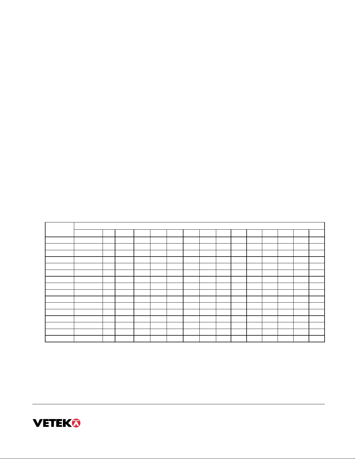
1. Determine the number of desired external graduations and choose the corresponding value listed in Table C-1 under the number closest to
your full-scale input range in millivolts.
2. Enter the Setup Menu and save this number for the Span Gain parameter in F2.
3. Perform a system calibration. If the calibration proves unsuccessful, or you wish to view the internal counts, proceed to the next set of
instructions.
VIEWING THE INTERNAL COUNTS
1. Enter the zero calibration menu (F16) and follow steps 1 to 3, but do not save the zero point.
2. After pressing ZERO to zero the offset, place the test weight(s) on the platform. The displayed count is the internal count. If the count
remains on zero, check your load cell connections.
3. At full scale, the displayed count should be a minimum of 2 times the desired external graduations. However, for maximum stability, a ratio
of 6:1 or higher is recommended.
4. If the displayed count is large enough, remove the test weight(s), re-zero the indicator if necessary, and proceed with the calibration. If the
displayed number is not large enough, increase the Span Gain to the next highest choice in the Setup Menu and re-calibrate.
External Full Scale Input Range (mV/V)
Grads 0.2 0.4 0.6 0.8 1.0 1.2 1.4 1.6 1.8 2.0 2.2 2.4 2.6 2.8 3.0
500 75 50 25 25 25 25 25 25 25 25 25 25 25 25 25
1,000 150 75 50 50 25 25 25 25 25 25 25 25 25 25 25
1,500 200 100 75 50 50 50 25 25 25 25 25 25 25 25 25
2,000 – 150 75 75 50 50 50 50 25 25 25 25 25 25 25
2,500 – 200 100 75 75 50 50 50 50 50 50 25 25 25 25
3,000 – 200 150 100 75 75 50 50 50 50 50 50 50 25 25
4,000 – – 150 150 100 75 75 75 50 50 50 50 50 50 50
5,000 – – 200 150 150 100 100 75 75 75 75 50 50 50 50
6,000 – – –
200 150 150 100 100 75 75 75 75 75 50 50
8,000 – – – –
200 150 150 150 100 100 100 75 75 75 75
10,000 – –
– – –
200 200 150 150 150 150 100 100 100 75
12,000 – –
– – – –
200 200 150 150 150 150 150 100 100
15,000 – – – – – – – –
200 200 200 150 150 150 150
20,000 – – – –
– – – – – – –
200 200 200 150
30,000 – – – – – – – – – – – – – – –
40,000 – – – – – – – – –
– – – – – –

Manual page 9
USER (“A”) MENU
ENTERING THE USER MENU
1. Enter the Setup (“F”) menu by following the directions above.
2. Use the right or left directional keys shown in Figure 3-3 to move right or left in the Setup (“F”) menu until the indicator shows ” A 1”.
NAVIGATING IN THE USER MENU
1. Use the directional keys shown in the Figure to move around in the User Menu Chart.
2. To move to the selection level, press ZERO/OFF (down) key once. The current saved selection is shown.
3. To move to a new “F” heading, use TARE (left) or ON/PRINT (right) key to move right or left in the User Menu Chart.
4. If you want to go back whithout saving press lb/kg.
5. If a digit flashing, use lb/kg and ZERO/OFF for choosing value.
6. To save a new selection, press the NET/GROSS (Set) key .To exit without saving, press the PRINT (up) key to return to the current “F”
heading.
7. You can cancel calibration anytime with switching back to normal mode. An alternative is to disconnect the power.
A1
Baud Rate
1200 2400 4800 9600
A2
Data Bits, Parity
8n 7O 7E
A3
Transmission Mode
Cd
A4
Display Check
A5
Enable lb/kg Key
01
Press ZERO
key to begin
A7
ID No. Enable
A6
Serial Port Mode
01 01
A8
ID No. Entry
Press ZERO
key to begin
A9
No. of Line Feeds
Press ZERO
key to begin
7n
A10
Auto Power Off
5 8 10 15
OFF 12 3 20 30
ID Number Entry (A8)
1. While in the User Menu mode, scroll to "A 8", then scroll down once using the ZERO key to enter the ID Number menu.
2. The display will momentarily show "ID NO", followed by a value with one flashing digit.
3. Use the four directional keys to adjust the displayed value to the actual ID Number value. Increase/decrease the flashing digit by pressing
the lb/kg or ZERO/OFF key.
4. After setting the exact value, press the NET/GROSS key to save the ID Number value. The display will show "SET" momentarily, then
revert back up to A8.
LF (Line Feeds) Number Entry (A9)
1. Go to “A9”.
2. The display will momentarily show "LF", followed by the current line feeds value.
3. Use the four directional keys to adjust the displayed value
4. After setting the exact value, press the NET/GROSS key to save.

Manual page 10
USER MENU DESCRIPTIONS AND PROCEDURES
Factory-set defaults are shown in bold.
NAME/COD
E
DESCRIPTION CODE/VALUE
A1
Baud Rate
Selects the baud rate for data transmission through the serial port. 1200 2400
4800 9600
A2
Data Bits and
Parity
Selects the number of data bits and parity of serial transmission.
"8n" = 8 data bits with no parity bit and one stop bit
"7O" = 7 data bits with odd parity bit and one stop bit
"7E" = 7 data bits with even parity bit and one stop bit
"7n" = 7 data bits with no parity bit and two stop bits
8n
7O
7E
7n
A3
Mode of Serial
Transmission
Selects when data will be sent out of the serial port to a printer or computer:
"C" = Continuous mode; send data continuously
"d" = Demand mode; send data when a PRINT command is issued from the
printer, computer, or indicator.
C
d
A4
Display Check
Actuates the function that illuminates all digit segments, decimal points, and
LCD annunciators in a test sequence. Pressing the ZERO key to scroll
down one level begins the test sequence.
Press ZERO key to
begin sequence
A5
Disable the
lb/kg Key
Allows the lb/kg key to be disabled so that an operator cannot accidentally
press the key and change the displayed units.
"0" = Disable the lb/kg key "1" = Enable the lb/kg key
0 (CE)
1 (US)
A6
Serial Port
Mode
Selects the mode of the RS-232 serial port: Refer to Bilaga B for more
information.
"0" = Full Duplex Mode
"1" = Print Ticket Mode
0
1
A7
ID No. Enable
Allows the ID number to be disabled in the Print Ticket mode. Valid only
when A6 is set to “1”.
"0" = Disable the ID No. "1" = Enable the ID No.
0
1
A8
ID No. Entry
Actuates the function that allows entry of a new ID No. Valid only when A6
is set to “1”. Pressing the ZERO key to scroll down one level begins the
sequence.
0 - 199999 (500)
0 - 999999 (500E)
123456
A9
No. of Line
Feeds
Actuates the function that allows entry of the desired number of line feeds to
be printed in Print Ticket Mode. Valid only when A6 is set to “1”. Pressing
the ZERO key to scroll down one level begins the sequence.
0 - 99
5
A10
Auto Power
Off Period
Selects the auto off time period in minutes:
“Off” = Disabled (Always ON)
Off
1, 2, 3, 5, 8,
10, 15, 20, 30

Manual page 11
CALIBRATION
The indicator is calibrated by following the procedures embedded in F16 (Zero) and F17 (Span) of the Setup Menu.
Each procedure enters a value into the indicator's non-volatile memory - F16 the zero value (deadweight) and F17 the span value (test weight).
The minimum test weight that can be used is 1% of full-scale capacity. After the two calibration procedures are executed successfully, you
should record both calibration values using the F18 View procedure.
In the unlikely event that either value is lost while in the field, the setup menu makes provisions for re-entering these values via F19 and F20,
thus eliminating the need for re-calibration with test weights.
NOTE: This chapter assumes that the indicator is in Setup (“F”) Menu mode. If the indicator is not in Setup Menu mode, refer to Chapter 3 for
instructions.
ZERO CALIBRATION (F16)
1. While in the Setup mode, scroll to "F 16", then scroll down once using the ZERO key to enter zero calibration menu. The display will
momentarily show "C 0" followed by a value. This value is the internal A/D count and can prove useful when trying to troubleshoot setup
problems.
2. After making sure that there are no test weights on the platform, press the ZERO key to zero out the displayed value.
3. Press the NET/GROSS key to save the zero point value. The display will show "EndC0" momentarily, then revert back up to F16. At this
time, proceed to the F17 span calibration to complete indicator calibration.
SPAN CALIBRATION (F17)
1. While in the Setup mode, scroll to "F 17", then scroll down once using the ZERO/OFF key to enter span calibration menu.
2. The display will momentarily show "C 1" for the span calibration, followed by a value with one flashing digit. This value will be zero with
the Decimal Point parameter selected in F10. Place the test weight on the weighing mechanism.
3. Use the four directional keys to adjust the displayed value to the actual test weight value. Increase the flashing digit by pressing the lb/kg
key. Decrease the flashing digit by pressing the ZERO key. Pressing the TARE key or the PRINT key will change the position of the
flashing digit.
4. After setting the exact value, press the NET/GROSS key to save the value.
5. If the calibration was successful, the display will show "EndC1" momentarily, then revert back up to F17. At this time it is suggested that
the calibration values be recorded for future use.
6. If the calibration was not successful, one of the error messages below will appear. Take the indicated action to correct the problem, then
perform a new calibration.
"Err0" The calibration test weight or the adjusted keyed-in weight is larger than the full capacity of the scale. Change the
calibration test weight or check the input data.
"Err1" The calibration test weight or the adjusted keyed-in weight is smaller than 1% of the full capacity of the scale.
Change the calibration test weight or check the input data.
"Err2" The internal resolution of the scale is not high enough to accept the calibration value. Select a larger parameter for
the Span Gain (F2).
VIEW CALIBRATION VALUES (F18)
Note: The values displayed in this procedure are valid only after a successful calibration has been performed using F16 and F17.
1. While in the Setup mode, scroll to "F 18", then scroll down once using the ZERO key to enter View calibration menu.
2. The display will momentarily show "CAL 0" followed by a value. This value is the zero calibration value and should be
recorded in the table below. Press any key to continue.
3. The display will momentarily show "CAL 1" followed by another value. This value is the span calibration value and should
also be recorded in the table below. Press any key to return to upper level (F18).
INDICATOR ZERO CALIBRATION VALUE SPAN CALIBRATION VALUE
S/N:

Manual page 12
KEY-IN ZERO CALIBRATION VALUE (F19)
Note: This procedure is intended for emergency use only in the case of non-volatile memory loss. A valid zero calibration value,
obtained from a successful F16 calibration procedure, must be used.
1. While in the Setup mode, scroll to "F 19", then scroll down once using the ZERO key.
2. The display will momentarily show "CAL 0", followed by a flashing zero. Use the four directional keys to adjust the
displayed value to the zero calibration value.
3. After setting the exact value, press the NET/GROSS key to save the value.
4. The display will show "E CAL 0" momentarily, then revert back up to F19.
KEY-IN SPAN CALIBRATION VALUE (F20)
Note: This procedure is intended for emergency use only in the case of non-volatile memory loss. A valid span calibration value,
obtained from a successful F17 calibration procedure, must be used.
1. While in the Setup mode, scroll to "F 20", then scroll down once using the ZERO key.
2. The display will momentarily show "CAL 1", followed by a flashing zero. Use the four directional keys to adjust the
displayed value to the span calibration value.
4. After setting the exact value, press the NET/GROSS key to save the value.
5. If the entered value is greater than zero, the display will show "E CAL 1" momentarily, then revert back up to F20. If a
value of zero is entered, the indicator will briefly show "Err 5", then revert back to the screen described above in Step # 2.

Manual page 13
SPECIFICATIONS
ANALOG SPECIFICATIONS
Full Scale Input Signal 30 mV, including dead load
Minimum Sensitivity 1.0 uV / grad
Input Impedance 30 Mohm, typical
Internal Resolution Approximately 150,000 counts
Display Resolution 50,000 display division max
Measurement Rate 10 Meas/sec, nominal
System Linearity Within 0.02% of FS
Calibration Method Software Calibration, with long term storage in EEPROM
Excitation Voltage +5 VDC, 4 x 350 ohm load cells
DIGITAL SPECIFICATIONS
Microcomputer Winbond W78E58
Program Memory: 32K x 8, internal to uC
SRAM 256 x 8, internal to uC
EEPROM: 256 x 8, external to uC
Digital Filtering Software selectable
SERIAL COMMUNICATIONS
Serial Port Full Duplex, 1200, 2400, 4800, 9600 Baud
8 data bits, no parity, 1 stop bit
7 data bits, odd parity, 1 stop bit
7 data bits, even parity, 1 stop bit
7 data bits, no parity, 2 stop bits
OPERATOR INTERFACE
Display 0.75" (19 mm) 7-segment, Liquid Crystal, 6-Digit
Additional Symbols Net, Gross, Stable, Tare, lb, kg, Zero
Keyboard 5-key flat membrane panel
POWER
Rechargeable Battery 6 VDC, 3.0 Ah Sealed lead acid (e.g. Yuasa
NP3-6 Dimension H67 x W134 x D34 mm)
AC Adapter 9 VDC, 800 mA
DC Power Consumption 55 mA + 15 mA/350 ohm Load Cell
ENVIRONMENTAL
Operating Temperature -10 to +40 grad C
Storage Temperature -25 to +70 grad C
MECHANICAL
Overall Dimensions (with stand) 10.4” x 7.5"x 2.9” (265 mm x 191 mm x 73 mm)

Manual page 14
SERIAL PORT INFORMATION
FULL DUPLEX MODE
The Full Duplex Mode provides a Demand serial transmission mode and is selected by setting A3 to “d” and A6 to “0”. The Demand mode
allows control from a host device, usually a PC, and can be activated by pressing the PRINT key on the indicator’s front panel. Figure B-1
shows a suggested cable diagram for interface to a PC. Figure B-2 shows the serial data format for the Demand Mode.
INDICATOR PC
2 RXDRXD 2
TXD 3
S. GND 5
3 TXD
5 S. GND
6 DSR
4 DTR
8 CTS
DSUB9 DSUB9
FIGURE B-1. Cable Diagram for Indicator to IBM PC
<STX> <POL> xxxxx.xx <LB/KG> <GR/NT> <CR> <LF>
Polarity:
<SP> = Positive
"–" = Negative
Weight Data
Units:
lb = pound
kg = kilogram
Gross/Net:
GR = Gross
NT = Net
Start
Transmission
Carriage
Return
Line
Feed
<SP> <SP>
SpaceSpace
pc = pieces
cu = cusotm unit
FIGURE B-2. Consolidated Controls Demand Mode
RECOGNIZED HOST COMMANDS
“P” - This command is sent to the indicator to print the indicated display. The indicator will not respond if the scale is in motion,
positive overload or negative overload.
“Z” - This command is sent to the indicator to zero the scale. The indicator will not respond if the scale is in motion, positive
overload or negative overload. The indicator will also not respond if it is not in gross mode or within the zero range specified in
F4 of the Setup Menu.
“T” - This command is sent to the indicator to tare the scale. The indicator will not respond if the scale is in motion, positive overload
or negative overload. The indicator will also not respond if it displaying a negative gross value.
“G” - This command is sent to the indicator to revert to gross mode. The indicator will not respond if the scale is in motion, positive
overload or negative overload. The indicator will also not respond if it is not in net mode.
“N” - This command is sent to the indicator to revert to net. The indicator will not respond if the scale is in motion, positive overload
or negative overload. The indicator will also not respond if it is not in gross mode or a tare has yet to be established.
“C” - This command is sent to the indicator to toggle among the configured units.

Manual page 15
PRINT TICKET MODE
The Print Ticket Mode is designed specifically for a serial printer and is selected by setting A6 to “1”. Figure B-3 shows the fixed format of the
print ticket.
For printers with limited buffers, this mode supports DTR pin handshaking. The DTR pin from the serial printer is wired to the indicator’s RXD
pin which then functions as a CTS pin. Figure B-4 shows a suggested cable diagram for interfacing to a serial printer. Refer to the printer’s user
manual to confirm which pin is the DTR pin.
NOTES:
1. The TARE and NET fields are not printed unless a tare has been established in the system.
2. The ID number field is not printed if it is disabled in A7 of the User Menu.
ID. NO. 123456
GROSS 25.00 LB
TARE 1.48 LB
NET 23.52 LB
INDICATOR PRINTER
3 RXDCTS 2
TXD 3
S. GND 5
20 DTR
7 S. GND
DSUB9 DSUB25
FIGURE B-3. Print Ticket FIGURE B-4. Cable Diagram for Indicator to Printer
SIMPLEX MODE
The Simplex Mode provides a continuous serial transmission mode and is selected by setting A3 to “C” and A6 to “0”. The Continuous mode is
used to interface to computers, scoreboards, and other remote devices requiring constant data updating. The transmission occurs at the end of
each display update. Figure B-5 shows the serial data format for Continuous Mode.
<STX> <POL> xxxxx.xx <L/K> <G/N> <STAT> <CR> <LF>
Polarity:
<SP> = Positive
"–" = Negative
Weight Data
Units:
L = pound
K = kilogram
Gross/Net:
G = Gross
N = Net
Start
Transmission
Carriage
Return
Line
Feed
Status:
<SP> = Valid
M = Motion
O = Over/under range
P = pieces
C = custom units
FIGURE B-5. Consolidated Controls Continuous Mode

Manual page 16
DISPLAYED ERROR CODES
CODE MODE MEANING / POSSIBLE SOLUTION
Normal
Operating Mode
Gross Overload. A weight greater than the rated capacity has been applied to
the scale. Remove the weight from the platter or try re-calibrating the scale.
Otherwise, check for a bad load cell connection or possible load cell damage
due to overloading.
Normal
Operating Mode
Indicates that the battery voltage is too low for normal operation. Re-charge
the battery.
Err 0 Span
Calibration
Mode (F17)
Keyed-in weight value is larger than full scale capacity. Use a smaller test
weight or check keyed-in value.
Err 1 Span
Calibration
Mode (F17)
Keyed-in weight value is less than 1% of full scale capacity. Use a larger test
weight or check keyed-in value.
Err 2 Span
Calibration
Mode (F17)
There is not enough load cell signal to produce the internal counts necessary to
properly calibrate the scale. First check all load connections. Use F16 mode to
view internal counts. See Appendix C for more information.
Err 3 All Modes Non-volatile memory read error. One or more setup parameters have been lost.
Err 4 All Modes Non-volatile memory write error. Indicator needs service.
Err 5 Key-in Span
Calibration
Mode (F20)
You have attempted to enter a zero value for C1. Enter a known calibration
value greater than zero.
Err 7 Initialization No reading from the ADC. Make sure there is a load cell(s) connected to the
indicator at start-up.
Err 9 Normal
Operating Mode
Span calibration value has been lost. Re-calibrate the scale.
Fault localization
If it is problem to get a reading on the display or it is important to calibrate. This instruction ia valid for Loadcells with Sensitivity 2 mV/V
1. Check the excitation voltage (E+ and E-) from the Indicator. Should be 5,0 (+-0,2) VDC.
2. Check the input to the Indicator (S+ and S-). Should be aprox 0 to +10 mV for the capacity range for above model of Loadcells.
Note S+ is plus and S- is minus. The polarity is important.
3. If the input is wrong, <0 mV or > +10 mV with unloaded Scale check the Loadcells individually. Do have only E+ and E- connected
(or probably an external Power 5 VDC) and checks the output from the Loadcells direct on the wires. Should be 0 mV to +10 mV
depending on the load. (If you have external power e.g. 12 VDC the output should be 0 mV to +24 mV).
4. If all Loadcells seems to be okay connect all parallel to the Indicator and try to calibrate again. If it not is possible check the input
S+ and S-. It should be an average value of all Loadcell outputs.

Manual page 17
OPERATION
LCD Annunciator MEANING
Î0ÍBetter known as the “Center of Zero” annunciator, this light is active whenever the
displayed weight is within ± 0.25 divisions of true zero.
N Indicates that the indicator is displaying net weight.
G Indicates that the indicator is displaying gross weight.
T Indicates that a tare weight has been established in the system.
lb, kg Indicates the unit of the displayed weight.
Indicates a low battery condition. Re-charge the battery.
Indicates stable reading

Manual page 18
KEYBOARD
The keyboard is composed of five function keys.
FUNCTION KEYS
lb/kg – This key toggles the indicator between lb and kg units if enabled in the User (“A”) Menu
Zero - This key sets the indicator to display zero provided the following conditions are met:
1. The indicator is displaying Gross weight.
2. The displayed weight is within the zero reset range that is programmed in F4 of the Setup (“F”) Menu.
3. The scale is not in motion.
4. The scale is not in overload.
NOTE:When the ZERO key is held for three seconds, it shuts the indicator off.
Net/Gross - This key toggles the indicator between Gross weight and Net weight only if a Tare has been established.
Tare - This key is used to establish a Tare provided the following conditions are met:
1. The indicator is not at or below Gross zero.
2. The scale is not in motion.
3. The scale is not in overload.
Print - This key is used to send weight information out to the serial port provided the following conditions are met:
1. The scale is not in motion.
2. The scale is not in overload.
NOTE:When the indicator is off, the PRINT key is used to turn the indicator on.
GENERAL SCALE OPERATION
WEIGHING AN ITEM
1. Select the desired weighing unit by pressing the lb/kg key until that unit is indicated on the display.
2. If necessary, press the ZERO key to obtain a weight reading of zero.
3. Place the object to be weighed on the scale’s platter and allow the weight indication to stabilize. If the item weight exceeds
the scale’s weight capacity, it displays “”.
4. Read the weight shown on the display.
TARING AN ITEM
To weigh an item in a container, the weight of that container must first be subtracted from the overall weight to obtain an
accurate weight reading. This is known as taring.
1. Select the desired weighing unit by pressing the lb/kg key until that unit is indicated on the display.
2. If necessary, press the ZERO key to obtain a weight reading of zero.
3. Place the empty container on the scale’s platter and allow the weight indication to stabilize.
4. Press the TARE key. The display shows zero weight and turns the NET annunciator on.
5. Place the material to be weighed in the container and allow the weight indication to stabilize.
6. Read the weight shown on the display.
You may toggle between the gross weight and the net weight by pressing the NET/GROSS key.
This manual suits for next models
1
Table of contents
Other Vetek Measuring Instrument manuals