VETRON 5000 User manual

5000 » SERVICE MANUAL
05/2015

SERVICE MANUAL VETRON 5000 03
06 01. OPERATING ELEMENTS
07 01.01. OVERVIEW
08 01.02. OPERATING FIELD VETRON P107
09 01.03. HOTKEYS
10 01.04. ELECTRONIC HAND WHEEL & REVERSE SEWING
11 01.05. CONTROL & MAIN SWITCH
12 01.06. PEDAL
13 01.07. LIGHT
14 02. GENERAL INFORMATION
15 02.01. GENERAL INFORMATION IMPORTANT FOR
SAFETY AND ADJUSTMENTS
16 02.02. TOOLS AN GAUGE PARTS
17 02.03. ACTIVATE THE ADJUSTMENT WIZARD
18 02.04. OVERVIEW
19 02.05. SAVE OR DISCARD
20 02.06. BASIC PARAMETER RESET
21 02.07. PARAMETER LIST
28 03. ADJUSTMENT
33 03.01. SYNCHRONISATION OF THE MAIN DRIVE WITH THE MACHINE
34 03.02. ADJUSTMENT OF THE MATERIAL THICKNESS MEASUREMENT SYSTEM
35 03.03. STEPPER MOTOR BASIC ADJUSTMENT
35 ADJUSTMENT OF THE FOOT STROKE REFERENCE POSITION
36 ADJUSTMENT OF THE STITCH LENGTH REFERENCE POSITION

04 SERVICE MANUAL VETRON 5000
37 03.04. ADJUSTMENT OF THE FEEDING DEVICE
38 03.05. ADJUSTMENT OF THE LIFTING MECHANISM
39 03.06. PREADJUSTMENT OF THE NEEDLE BAR HEIGHT
40 03.07. BASIC ADJUSTMENT OF THE NEEDLE BAR FRAME DRIVING LEVER
41 03.08. BASIC ADJUSTMENT OF THE NEEDLE BAR FRAME DRIVE ECCENTRIC
42 03.09. BASIC ADJUSTMENT OF THE NEEDLE BAR FRAME
44 03.10. BASIC ADJUSTMENT OF THE FEED SHAFT CLAMP
45 03.11. DISTANCE BETWEEN HOOK AND NEEDLE
46 03.12. NEEDLE RISE
47 03.13. NEEDLE HEIGHT
48 03.14. NEEDLE GUARD
49 03.15. ADJUSTMENT OF THE FEED DOG POSITION INSIDE THE STITCH PLATE
50 03.16. ADJUSTMENT OF THE FEED DOG HEIGHT
51 03.17. PREADJUSTMENT OF THE BOBBIN CASE OPENER
52 03.18. TOP FEED ECCENTRIC
53 03.19. TOP FEED STROKE
54 03.20. HOOK OIL SUPPLY
55 03.21. ADJUSTMENT OF THE STITCH LENGTH CORRECTION
56 03.22. RESTING POSITION OF THE ROLLER LEVER
57 03.23. PREADJUSTMENT OF THE CONTROL CAM
58 03.24. THREAD CATCHER HEIGHT
60 03.25. LATERALLY ADJUSTMENT OF THE THREAD CATCHER
61 03.26. KNIFE POSITION AN PRESSURE
62 03.27. THREAD CATCHER RESTING POSITION
63 03.28. BOBBIN THREAD CLAMP
64 03.29. THREAD CUTTING TIMING (CONTROL CAM)
65 03.30. ADJUSTMENT OF THE THREAD TAKE UP SPRING TENSION
66 03.31. ADJUSTMENT OF THE THREAD TAKE UP SPRING TRAVEL

SERVICE MANUAL VETRON 5000 05
67 03.32. THREAD TENSION SERVICE
67 THREAD TENSION CHECK
68 DISASSEMBLY OF THE THREAD TENSION DEVICE
69 ASSEMBLY AND ADJUSTMENT OF THE THREAD TENSION DEVICE
70 03.33. PEDAL
71 03.34. ELECTRICAL EDGE GUIDE
72 03.35. SEWING AND FUNCTIONS CHECK
73 03.36. DURABILITY CHECK

06 SERVICE MANUAL VETRON 5000
01. OPERATING ELEMENTS

ESC
P000 30%
TEST
SERVICE MANUAL VETRON 5000 07
01. OPERATING ELEMENTS
01.01. OVERVIEW
1 OPERATING FIELD (page 8)
2 HOTKEYS (page 9)
4 CONTROL (page 11) 5 USB-DONGLE 6 PEDAL (page 12)
3 ELECTRONICS AND SEWING
REVERSE (page 10)

1 2 3 4
5 6 7 8 9
A B
ESC
000
SE T
30%P
T10
08 SERVICE MANUAL VETRON 5000
01. OPERATING ELEMENTS
01.02. TYPICAL OPERATING FIELD P107
The operating fi eld indicates the current operating states.
Operation takes place via continuous dialog between control and operator.
Depending on the operating state, di erent texts are displayed.
The following functions are assigned to the BUTTONS ABOVE AND BELOW THE DISPLAY:
1 BACKTACK (from left to right):
1. Start backtack
2. End backtack
2 THREAD TRIMMING
3 NEEDLE UP/DOWN AFTER STOP
4 LIGHT ON/OFF
5 PARAMETERS
6 NEW PROGRAM
7 PROGRAMMED SEAM
8 SAVE
9 CANCEL
If a function is activated, this is indicated by illuminating the corresponding LED.
In order to CHANGE OR SET VALUES, use the JOG Key ( 10 ):
Turning changes the values; pressing the JOG Key enters the value.
In the following, the operating type is indicated by the following icons:
Input = Press the JOG Key:
Change = Turn the JOG Key:

1
2
4
3
SERVICE MANUAL VETRON 5000 09
01. OPERATING ELEMENTS
01.03. HOTKEYS
1 SAFETY SWITCH
If the safety switch is triggered, all functions are locked. The LED lights up red.
CAUTION:
Before activating the machine by the X-button make sure to remove sewing material
or other items below the sewing feet if necessary and follow the instructions displayed
in the control panel.
2 SINGLE BACKTACK SUPRESSION
If the backtack function is activated, the following backtack is switched o one time
by pushing the key.
BACKTACK ON/OFF
If the backtack function is deactivated, the backtack is switched on by pushing the key.
3 2ND STITCH LENGTH
If the second stitch length is activated, the adjacent LED is lit up.
4 CUSTOMIZABLE BUTTON
Default: Toggle foot stroke level

1
2
3
10 SERVICE MANUAL VETRON 5000
NOTE!
The electronic handwheel is not active unless the machine has performed at least one stitch.
For safety reasons it is necessary during “blocked mode” to push and hold
the programmable button (the lowest button) 3 to activate the handwheel.
1 ELECTRONIC HAND WHEEL – FUNCTION
» By turning the hand wheel, you can move the needle bar forwards or backwards.
In the following, the operating type is indicated by the following icons:
Pressing the hand wheel: stitch-for-stitch function / needle positioning
Turning the hand wheel:
2 REVERSE SEWING
Pulling the button changes the sewing direction.
stitch-for-stitch function / needle positioning
01. OPERATING ELEMENTS
01.04. ELECTRONIC HAND WHEEL & REVERSE SEWING

1
2
SERVICE MANUAL VETRON 5000 11
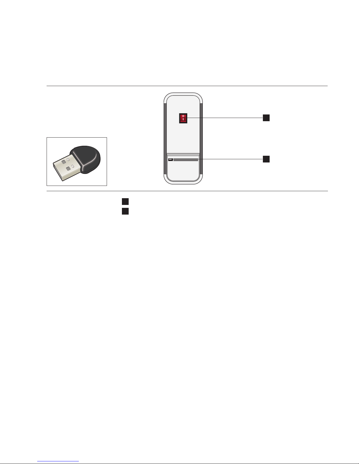
1 MACHINE MAIN SWITCH ON/OFF
2 USB-PORT
Identify yourself using the provided USB dongle.
01. OPERATING ELEMENTS
01.05. CONTROL & MAIN SWITCH

0
+1
-2
+2
-1
12 SERVICE MANUAL VETRON 5000
01. OPERATING ELEMENTS
01.06. PEDAL
0 IDLE POSITION
+1 CONSTANT SEWING SPEED (adjustable via parameter M502)
+2 VARIABLE SEWING SPEED FROM 0-100%
OF THE CHOOSEN MAXIMUM SPEED (depending on sewing program)
-1 SEWING FEET LIFT
-2 SEAM END PROCEDURE ACTIVATION (depending on sewing program)

SERVICE MANUAL VETRON 5000 13
01. OPERATING ELEMENTS
01.07. LIGHT
The VETRON head module for sewing is equipped with LED sewing area lighting,
whose intensity can be controlled via the operating field.
For SWITCHING the light ON and OFF, press button »
To ADJUST THE LIGHT INTENSITY, proceed as follows:
DISPLAY STEP DESCRIPTION
» ADJUST LIGHT INTENSITY
11 Press the LIGHT button
►
The corresponding LED on
the display lights up
2r sig %h ne 00st 1B► Change LIGHT INTENSITY Percentage on the display and
light intensity of the light are changed.
3r sig %h ne 60s tB After 2 seconds without further input,
the value is set and the current program
number is shown
4P000
EMP O R AG N
Machine is ready for operation.

14 14 SERVICE MANUAL VETRON 500014
02. GENERAL INFORMATION

15SERVICE MANUAL VETRON 5000 15 15
02. GENERAL INFORMATION
02.01. GENERAL INFORMATION IMPORTANT FOR SAFETY AND ADJUSTMENTS
ATTENTION!
Please refer to all CHAPTER 1 SAFETY of the general instruction book.
It is very important that all safety devices are reassembled correctly after adjustment procedure.
ATTENTION! RISK OF INJURY!
While in adjustment mode the pedal is generally blocked. The red LED light at the machine head
is illuminated constantly.
If all three LEDs on the head are flashing simultaneously, the machine is temporarily activated
and waiting for user input.
All adjustment procedures are referring to a completely assembled machine and may only be
executed by a specially trained technician. Machine covers which need to be removed for adjust-
ment procedures may not be described in the text. The order of the following chapters is corres-
ponding with the useful sequence of performing a full adjustment of the machine. For performing
single adjustment steps, please see also the chapters above and below.

16 16 SERVICE MANUAL VETRON 500016
02. GENERAL INFORMATION
02.02. TOOLS AND GAUGE PARTS

17SERVICE MANUAL VETRON 5000 17 17
02. GENERAL INFORMATION
02.03. ACTIVATE THE ADJUSTMENT WIZARD
DISPLAY STEP DESCRIPTION
» ACTIVATE THE ADJUSTMENT WIZARD
01 Turn on the machine.
02 Wait until the message PRESS PEDAL
is appearing in the display.
03 PPEDSLRESA
RM A IV ELEMOTAER Press the pedal. INFO: After pressing the pedal the
machine is initializing itself.
04 P000
EMP O R AG N
Press the PARAMETER Key.
»
Via JOG Key the following functions are available.
S erievc
a gta an reamD
Basic rap ameter
...
05
» Turn the JOG Key if necessary
until SERVICE is appearing
in the Display.
06 S erievc » confi rm.
07 a u
z
si t
i ra
c ad t ensj mB
wd » confi rm.

18 18 SERVICE MANUAL VETRON 500018
02. GENERAL INFORMATION
02.04. OVERVIEW
S erievc a gta an reamD Basic rap ameter ...
a u
z
si t
i ra
c ad t ensj mB
wd r se te
e re m tBs aapcair
1
t
R
e pu
e po r vedsf i0
s 3
t
N t
e pu
e dl e ghhee i1
s 5
s
T r
o t ps u
h ea a chcdr t2
pe
2 s
s
M
y etupet s
a m e r u at e0
sm 4
t
N
e pu
e dl u rdgee a1
s 6
e
T
r r setupss e
h ea n fekdr i2
pu
3
i
R r
r etupev s
e po t ppssf e0
ds 5 o
t
F
e pu
edosgdep1
s 7
s
T r
e o setupts
h ea a chcdr t2
rp
4 r
t
F
e pu
e d v i de e0
s 6 o
i
F
e etuphg s
e d g d e1
ht 8
a
B d
l s tuppm e
o bi h eatnb r2
c
5 i
t
F
e pu
e d t f l e0
s t
7
e
B
p readjusen p
o b i a ec nb s1
or 9
m
T
i etupni s
h e a u c dr t2
tg
6
s
N
o e djustpa
e d l a b ee r0
pr 8 e
c
T t
c r c setupne i
o f i fd e p l1
et 0
r
T g
o s tupec e
a eu p inspk r3
f
7 i
v
T
e s tupre e
r n s s ns ma o0
l 9 e
t
T t
e pu
o f i fd e p l1
s 1
s
T g
o t ps u
a eu p inspk r3
pe
8
i
N
r e c setupev c
e d l a b ee r0
d 0 i
t
H
e pu
o k l o o2
s 2
r
T
e ei v
h ea e sntdr n3
sc
9
r
R e
a t ps u
e po e dlnsf e0
be 1
i
S
t etupct s
t t c n i h i2
sh 3 sPe al t ped u3
0 r
a
F
l p s setuppm o
e d v i de e1
c 2
s
R
o t ps u
o le e erlrl v2
pe 4
i
E
u s tuped e
l c t d ee re g3
g
1 e
s
H
i c setupat e
o k - d ee no l1
dn 3 l
e
C
r j s ta u
otr cmon a2
pd 5
n
S
u o testtc n
e i n n a gw d3
fi
2
t
N
e pu
e d l i er ee s1
s 4
i
T r
e djusthg a
h ea a chcdr t2
ht 6 t
s
A
e r veti
u o m c i a t3
td

19SERVICE MANUAL VETRON 5000 19 19
02. GENERAL INFORMATION
02.05. SAVE OR DISCARD
DISPLAY STEP DESCRIPTION
» DISCARD
01
If you want to discard the changes you
actually made press the ESCAPE Key.
»
INFO: The software jumps to the
last active item in the menue.
»SAVE
01 A
S
VE
E N/
S
YO
YES » confi rm.
INFO:
Your input is saved and the system
will proceed to the next item of the
adjustment wizard.
NO
» mark NO.
» confi rm.
INFO:
Your input is discarded and the
system will move to the last cho-
sen item of the adjustment wizard.

20 20 SERVICE MANUAL VETRON 500020
02. GENERAL INFORMATION
02.06. BASIC PARAMETER RESET
DISPLAY STEP DESCRIPTION
» BASIC PARAMETER RESET
01 Turn on the machine. Wait until the message PRESS PEDAL
is appearing in the display.
03 PPEDSLRESA
RM A IV ELEMOTAER Press the pedal. INFO: After pressing the pedal the
machine is initializing itself.
04 P000
EMP O R AG N
Press the PARAMETER Key.
»
Via JOG Key the following functions are available.
S erievc
a gta an reamD
Basic rap ameter
...
05 S erievc » Turn the JOG Key if necessary
until SERVICE is appearing
in the Display.
06 » confi rm.
07 » Turn the JOG Key if necessary until BASIC PARAMETER RESET
is appearing in the Display.
08 » confi rm. INFO:
The sofware will ask you to
confi rm that you wish to proceed.
09 >
0 2
t
00
n m classre -
- 0-015
E» to change the machine class
10 » confi rm.
11 >
0
t
0-
n s rialnrre e
0 5 2 25
E» to change the serial number
12 » confi rm. INFO:
The sofware will ask you to
confi rm that you wish to proceed.
13 A
S
VE
E N/
S
YO Choose YES to reset all basic parameters to the default values.
14 1
t
R
e pu
e po r vedsf i0
s
The software automatically switches to SYNCHRONISATION OF THE MAIN DRIVE WITH THE
MACHINE (03.01. / Page 31). You have to redo this point in order to proceed.
15 INFO:
Adjustment steps 03.12., 03.32. C, 03.33. (optional) and 03.34. (optional)
must be performed again.

21SERVICE MANUAL VETRON 5000 21 21
02. GENERAL INFORMATION
02.07. PARAMETER LIST
-1-10
# PARAMETER DISPLAY EN MIN MAX DEF. DESCRIPTION
M0XX - BASIC SEWING PARAMETERS:
010 Stitch length 1 0M 01 54 m
.m
1t g hShiltc nte -12.0 12.0 4.5 Unit: mm
011 Stitch length 2 0M 11 06 m
.m
2t g hShiltc nte -12.0 12.0 6.0 Unit: mm
013 Stitch length increase based on
material thickness
0M 31 OFF
tSclrnaim 1 100 OFF Unit: %
OFF
014 Stitch length material
thickness base
00 m
.m
kb
M 0 41
ea sSilcht 0 (= OFF) 10.0 OFF Unit: mm
015 Delay after thickness change,
before stitch lenght is changed
OFF
lade ySclred
M 0 51 0 20 OFF 0 - 20 stitches
016 Stitch length decrease
based on sewing speed
OFF
eesp dSclred
M 0 61 – – OFF OFF
1-100%
017 Stitch lenght speed base 3 m / iS n00 0
a sbd eSeleps
M 0 71 50 4000 3000 Unit: S/min
018 Stitch length trigger function 0 8 1M G
e
GT L
r
OE
igtr gS hit lct – – TOGGLE
You can choose between:
» OFF
» SWITCH
» TOGGLE
019 Stitch length maximum
according to sewing tool
0 9 1M
m
09 m
a
.m
xthngeS hit lct 3.0 12.0 9.0 Unit: mm
020 Foot stroke 1 0 0 2M 52 m
.m
e1Fsoro tkto 0.0 9.0 2.5 Unit: mm
021 Foot stroke 2 0 1 2M 06 m
.m
2eFsoro tkto 0.0 9.0 6.0 Unit: mm
027 Automatic stroke switch
according to sewing speed
0 7 2M OFF
we sAstru tkoo – – OFF
You can choose between:
» O N
» OFF
028 Automatic stroke switch
speed threshold
0 8 2M m / iS n03 0
e dp s eSerst ko w 50 4000 300 Unit: S/min
029 Automatic stroke switch delay 0 9 2M 0 40 .s
a ye d lSerst ko w 0.10 5.00 0.40 Unit: sec
030 Thread tension A 1 0 0 3M 25%
1n o ATtrnh eids 0 100 25 Unit: %
031 Thread tension A 2 0 1 3M 35%
2n o ATtrnh eids 0 100 35 Unit: %
032 Thread tension B 1 0 2 3M 25%
1n o BTtrnh eids 0 100 25 Unit: %
033 Thread tension B 2 0 3 3M 35%
2n o BTtrnh eids 0 100 35 Unit: %
Other manuals for 5000
5
Table of contents
Other VETRON Sewing Machine manuals

VETRON
VETRON 5000 Owner's manual

VETRON
VETRON 4000 User manual

VETRON
VETRON 5300 User manual

VETRON
VETRON 5000 User manual

VETRON
VETRON 5064 User manual

VETRON
VETRON 5390 User manual

VETRON
VETRON 5000 User manual

VETRON
VETRON 5400 User manual

VETRON
VETRON Typical GC6890 User manual

VETRON
VETRON 5000 User manual