Vetter VSL 12 User manual

Vetter Low Pressure Lifting Bags 0.5 bar / 7.25 psi
Vetter Medium Pressure Lifting Bags 1 bar / 14.5 psi
Vetter Low Pressure Bags 0.5 bar / 7.25 psi
14
List of contents
Introduction ..................... 14
Safety instructions ........... 14
Operating with com-
pressed-air cylinders ....... 15
Operating Low Pressure
Lifting Bags with dual
deadman controller ......... 16
Operating Low Pressure
Lifting Bags with dual fitting
controller ........................ 16
Operating with other com-
pressed-air sources ......... 17
Practical tips ................... 18
Troubleshooting .............. 18
Maintenance and
servicing ......................... 19
Recurrent tests ............... 19
- Performance ................ 19
- Tables ......................... 21
Technical data
- Low Pressure Lifting
Bags ........................... 22
- Medium Pressure Lifting
Bags ........................... 23
- Low Pressure Bags ...... 24
EC declaration of
conformity ....................... 25
Introduction
Lifting bags may only be
operated with compressed
air, never with flammable or
aggressive gases.The
lifting bags may only be
filled using original Vetter
fittings. Check the equip-
ment before and after every
use for perfect working
order. Pay attention to DIN
7716 if stored for longer
periods of time. We will be
happy to supply an excerpt
from this standard.
Safety instructions
• Use only Vetter original
fittings. Only these
fittings have been
tested in the works in
accordance with the
Pressure Vessel
Legislation.
• Please check the
perfect condition of the
equipment and lifting
bags before and after
use.
• Insert lifting bags at
suitable points so that at
least 75 % of the bag’s
surface is beneath the
load.
• Avoid angles larger than
30° (relationship
between base and load
to be lifted).The bag
could be catapulted out
of the gap. Create a
parallel base to the load
to be lifted whenever
possible using a sturdy
substructure.
• Never place more than
two bags on top of one
another.
• Secure load against
slipping. Keep inserting

Operating with com-
pressed-air cylinders
Connect pressure regulator
with T-screw to com-
pressed-air cylinder.
Close handwheel (3) of
pressure reducer.
Open cylinder valve (5):
manometer (1 ) shows the
pressure in the cylinder.
Set the back pressure to
approx. 2 bar with the ad-
justing screw (4) (display on
manometer (2)).
Connect pressure re-
ducer’s air supply hose to
dual controller with nipple.
Push nipple into coupling
until it catches.
15
props the higher the
lifting height.
• If a substructure is used
always ensure that this
is stable and firm.The
substructure must
support at least the
complete area of the
bag and should be
wider and longer than it
is high.
Danger
Risk of slipping
Never place metal on
metal when propping
up loads!
• Place stones, branches
or similar materials
under the bag to im-
prove adherence if used
on slippery sur-faces
(ice, snow, mud, etc.).
• Avoid point loads, e.g.
building cramps, bolts.
• Never use bags on
sharp edges or on very
hot days. Use suitable
liners and cover the
complete surface of the
bag.
• Protect bags against
flying sparks during
welding and cutting
work.
• Do not place extra loads
on bags, e g. hydraulic
props, winches, falling
loads.
•Never work under
suspended loads,
never reach under
load. Keep your
distance.
• Avoid shearing stresses
by squeezing the bag
when the load is
lowered.
•Never stand in front of
the bag, always to one
side when in use
since it can be cata-
pulted out from under
the load.
3
5
1
4
2

Operating Low Pressure
Lifting Bags with dual
fitting controller
Connect the controller to
the Lifting Bag with the
inflation hose.
Push nipple into twin-lock
coupling until it catches and
tighten by hand (9).
Place the bag in position.
Close the ball valve (6) and
discharge device (7) on the
head of the safety valve.
7.25 psi or 1 bar / 14.5 psi.
The lever automatically
returns to the middle posi-
tion = deadman position.
If the working pressure
exceeds 0.5 bar / 7.25 psi
or 1 bar / 14.5 psi the safety
valve opens.
The max. tolerance for
opening and closing the
safety valve may be
± 10 %.The manometer (8)
shows the pressure in the
bag.
Push the lever forwards to
deflate the Lifting Bag and/
or lower the load.
16
3
10
8
9
9
Operating Low Pressure
Lifting Bags with
dual deadman controller
Connect the controller to
the Lifting Bag with the in-
flation hose.
Push nipple into twin-lock
coupling until it catches and
tighten by hand (9).
Open the handwheel (3) on
the Vetter pressure regula-
tor.
Pull back the lever (10) on
the controller to inflate the
Lifting Bag.
Keep an eye on the mano-
meter (8) and the load.
Once the desired working
pressure for lifting force and
height is reached stop
inflation by releasing the
lever at a max. of 0.5 bar /
Vetter Low Pressure Lifting Bags 0.5 bar / 7.25 psi
Vetter Medium Pressure Lifting Bags 1 bar / 14.5 psi
Vetter Low Pressure Bags 0.5 bar / 7.25 psi

Open the handwheel (3) on
the Vetter pressure regula-
tor.
Open the ball valve (6) to
inflate the Lifting Bag and
raise the load.
Keep an eye on the internal
pressures in the bag shown
at the mano-meter (8) of
the dual controller and the
load.The safety valve
prevents an overfilling of the
bag.
Depending on the type,
position and behaviour of
the load during lifting, the
Lifting Bags are filled either
• simultaneously and
equally or
• gradually and / or
individually.
Close the ball valve imme-
diately in the event of a stop
or fault, find the cause and
remedy.
The max. tolerance for
opening and closing the
safety valve may be
± 10 %.The manometer (8)
shows the pressure in the
bag.
Open the discharge device
on the head of the safety
valve (7) by turning anti-
clockwise to deflate the
Lifting Bag and / or lower
the load.
Operating with other
compressed-air sources
Vetter adaptor sets are
available for other com-
pressed-air sources.
• Compressed-air mains
(15)
• Truck tyre inflator (16)
Warning
Tyre inflation connec-
tor must be protected
by a safety valve.
• Truck air brake
systems (17)
Warning
Seal off control line
with the dummy
coupling (18). Secure
truck with wheel
blocks.
17
3
7
6
8
6
7
18
17
16
15
20
21
19

placement of the lifting
bags, Vetter Mini Lifting
Bags can usually be used
to quickly create the
necessary space.
Troubleshooting
If a safety valve opens
prematurely because a
foreign body has pene-
trated the system, open the
discharge device at the
head of the safety valve
fully by turning anticlock-
wise so that compressed-
air can escape. If this does
not remove the foreign
body the top part of the
valve must be unscrewed.
Unscrew in an anticlock-
wise direction using a pipe
wrench. Carefully remove
the valve cone and remove
the foreign body in front of
the sealing plate. Screw the
top part of the valve back
on tight and check for
perfect operation.The pre-
set pressure may not be
changed. If the lead or
leaded plate on the top part
of the valve is removed a
safe function can no longer
be guaranteed - return the
device to the manufacturer.
• Truck tyre valve (19).
For inflation with a
normal hand or foot
pump.
• Truck tyre valve con-
nector (20).To take air
from the spare tyre.
• Building site com-
pressor (21).
• Hand (22) or foot (23)
pump with manometer.
Reducing adaptors and air
pumps are available from
the manufacturer.
If the maximum pressure
from the compressed-air
supply exceeds 4 bar /
58 psi a pressure reducer
must be used and the
pressure reduced to
approx. 2 bar / 29 psi.
Practical tips
You should normally use at
least two bags of the same
size and design. Place
each bag as close as
possible to the end of the
load.
Pull bag under the load with
a working line or lower
between loads to be
separated. On account of
the low bearing pressure
[maximum 0.5 kg / cm2
(7.25 psi) or 1.0 kg / cm2
(14.5 psi)] substructures
are rarely required, even on
soft bases.
Secure the load against
slipping during lifting by
bracing or other suitable
measures. Place Lifting
Bags completely under
load wherever possible
(though with at least 75% of
their surface).The lower the
contact area between the
lifting bag and load, the
lower the lifting power.
Place the side wall material
between the top and
bottom of the bag before
inserting under the load. If
the insertion height or area
is inadequate for a proper
18
22
23
Vetter Low Pressure Lifting Bags 0.5 bar / 7.25 psi
Vetter Medium Pressure Lifting Bags 1 bar / 14.5 psi
Vetter Low Pressure Bags 0.5 bar / 7.25 psi

f) Press patch firmly onto
prepared area of the
bag and rub.
g) Leave bag at least 48
hours in deflated state.
The bag should be tested
by a safety expert after the
repair.
Recurrent tests
Tests for lifting bags are
based on the Pressure
Vessel Legislation and DIN
14152 Part 1*.The tests
contained herein are to be
carried out as specified.
Lifting bags with a maxi-
mum working pressure of
0.5 bar / 7.25 psi do not
have to be tested by a
safety expert but can be
tested by a qualified tester.
Vetter Lifting Bags 0.5 bar /
7.25 psi are subjected to a
constructional and pres-
sure test as well as an
approval test in accordance
with § 9 of the Pressure
Vessel Legislation by a
work’s tester.
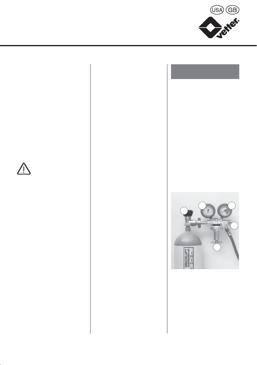
If this ices up because of a
excess atmospheric
humidity in connection with
low temperatures use a
normal defroster (such as
is used for car locks).
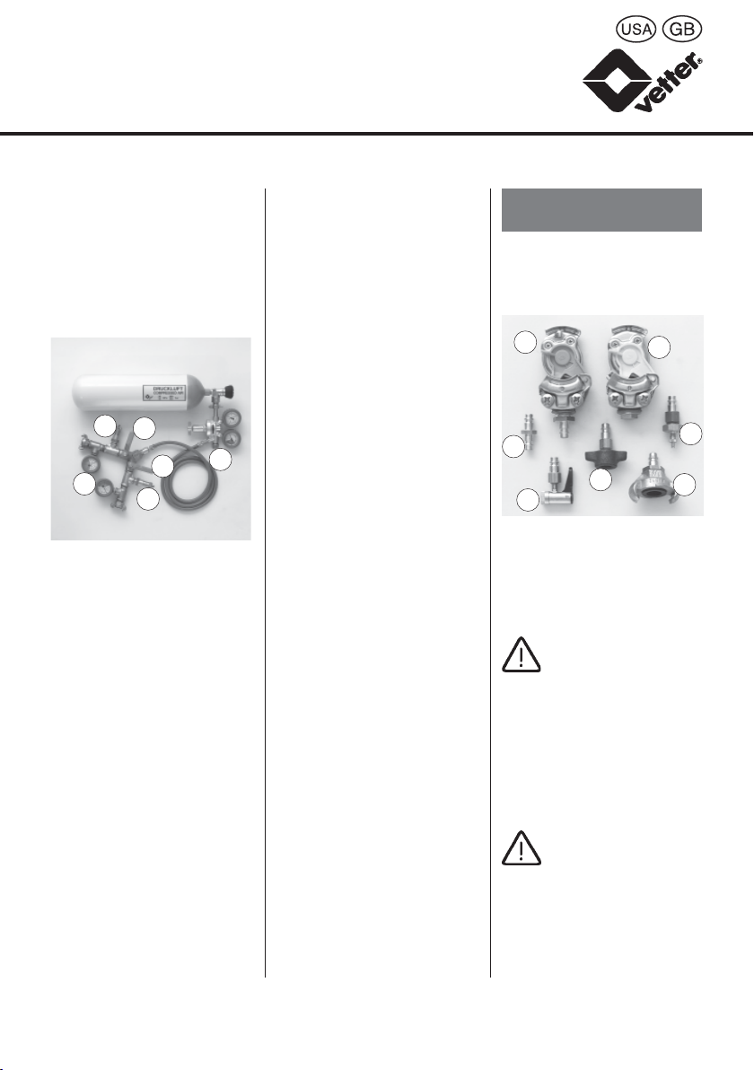
Maintenance and
servicing
Minor damage such as
cracks, cuts or punctures
can be repaired by the user
with the enclosed repair kit
as follows:
a) Select a patch which is
approx. 5 cm larger
than the damage on all
sides.
b) Mark patch on bag.
c) Roughen up the surface
of the bag and one side
of the patch.
d) Apply a thin layer of
special adhesive on the
roughened up surface
of the bag and the
patch.
e) Leave special adhesive
approx. 20 minutes to
dry until no longer tacky.
Performance of tests
Tests on delivery by user
During this test in accord-
ance with DIN 14 152 Part
1, Item 5.2*the device
should be checked by the
user’s qualified tester to
ensure that all parts have
been delivered and that
none are damaged.The
bags are to be inflated up to
0.2 times the permissible
working pressure, i.e. to 0.1
bar / 1.5 psi.The qualified
tester should then perform
a visual check.
Recurrent tests
The lifting bag system
should be checked after
every use, though at the
latest after one year, to
ensure that all parts are
complete and none are
damaged. If all parts are
complete and present the
lifting bag should be in-
flated to 0.5 times the
maximum working pres-
sure of 0.5 bar / 7.25 psi,
i.e. 0.25 bar / 4 psi, and
then washed with luke-
warm soapy water. Check
for cracks, wear, cuts or
19
*Pressure Vessel Legislation and DIN 14152 Part 1 are only valid in Germany.

other damage. Lifting bags
are made of neoprene-
coated fabric. However, air
diffuses through neoprene
(completely safe during
work with the bag). During
tests for leaks with leak-
finder spray and warm
soapy water this effect
appears as a fine-pore
foaming.This is typical for
the material and should not
be rated as a leak. Only if
air escapes profusely or
more than 10 % is lost after
1 hour should the bag be
repaired or returned to the
manufacturer.Otherwise
inflate the bag to the
maximum working pres-
sure of 0.5 bar / 7.25 psi
± 10 %. At 0.55 bar / 8 psi
the safety valve on the
controller should be fully
open, the pressure inside
the bag may not rise any
further.
If the safety valve does not
open fully, stop the test and
remedy the fault in the
manner explained under
“Troubleshooting”. Once the
fault has been remedi-ed
repeat this part of the test.
In accordance with the
Pressure Vessel Legislation
and DIN, the user is
responsible for the correct
performance of the re-
current tests.
We recommend that a
written record be kept of
the test and results.
Vetter offers courses to
train qualified testers.
20
Vetter Low Pressure Lifting Bags 0.5 bar / 7.25 psi
Vetter Medium Pressure Lifting Bags 1 bar / 14.5 psi
Vetter Low Pressure Bags 0.5 bar / 7.25 psi

Time Type of test Tester*Basis*
Interval
Before initial Acceptance inspection Work’s tester Pressure Vessel Legislation § 9
commissioning in manufacturer’s works
After receipt Check on delivery Qualified tester DIN 14 152, Part 1, Item 5.2
by the user
After every Visual and functional Qualified tester DIN 14 152, Part 1, Item 5.3.2
use inspection
Annually Visual and functional Qualified tester DIN 14 152, Part 1, Item 5.3.3
inspection
After repairs Test on special Qualified tester Pressure Vessel Legislation § 11
occasions
*Pressure Vessel Legislation and DIN 14152 Part 1 are only valid in Germany.
21
Table of recurrent tests

22
Vetter Low Pressure Lifting Bags 0.5 bar / 7.25 psi
Vetter Medium Pressure Lifting Bags 1 bar / 14.5 psi
Vetter Low Pressure Bags 0.5 bar / 7.25 psi
Technical data
Vetter Low Pressure Lifting Bags 0.5 bar / 7.25 psi
Model VSL 12 VSL 7 VSL 5 VSL 3
Type 0/12 I/6 II/4 III/3
DIN-code* LH50S LH30S LH20S LH10S
Product No.: complete set 111 00 000 112 00 000 113 00 000 114 00 000
Product No.: individual bag 111 01 000 112 01 000 113 01 000 114 01 000
Lifting power kN (to) 113 (11.3) 65 (6.5) 45 (4.5) 29 (2.9)
(2 bags = 1 set) US-tons 12.5 7.2 5 3.2
Lifting height cm 110 62 60 45
in. 43 24 24 18
Diameter cm 120 91 76 61
in. 47 36 30 24
Max. alowable bar 0.5 0.5 0.5 0.5
working pressure psi 7.25 7.25 7.25 7.25
Air req. for litres 3729 1209 816 393
2 bags cu.ft. 132 43 29 13.14
Nominal content litres 1243 403 272 131
1 bag cu.ft. 44 14 9.6 4.6
Test pressure bar 0.65 0.65 0.65 0.65
psi 9.4 9.4 9.4 9.4
Insertion ht. cm 3 3 3 3
(uninflated), in. 1.2 1.2 1.2 1.2
approx.
Weight, 2 bags kg 44 25 20 14
with valise lbs. 97 55 44 31
Weight kg 58 39 34 28
complete set lbs. 128 86 75 62

23
Vetter Medium Pressure Lifting Bags 1.0 bar / 14.5 psi
for export only
Model VSM 24 VSM 14 VSM 10 VSM 6
Type 1/230 1/130 1/90 1/60
DIN-code*
Product No.: complete set 311 00 000 312 00 000 313 00 000 314 00 000
Product No.: inidividual bag 311 01 000 312 01 000 313 01 000 314 01 000
Lifting power kN (to) 226 (22.6) 130 (13.0) 90 (9.0) 58 (5.8)
(2 bags = 1 set) US-tons 25 14.3 9.9 6.4
Lifting height cm 110 62 60 45
in. 43 24 24 18
Diameter cm 120 91 76 61
in. 47 36 30 24
Max. allowable bar 1.0 1.0 1.0 1.0
working pressure psi 14.5 14.5 14.5 14.5
Air req. for litres 4972 1612 1088 524
2 bags, cu.ft. 175 57 38 19
Nominal content, litres 1243 403 272 131
1 bag cu.ft. 44 14 9.6 4.6
Test pressure bar 1.3 1.3 1.3 1.3
psi 18.9 18.9 18.9 18.9
Insertion ht. cm 3 3 3 3
(uninflated), in. 1.2 1.2 1.2 1.2
approx.
Weight, 2 bags kg 45 26 21 15
with valise lbs. 99 57 46 33
Weight, kg 59 40 35 29
complete set lbs. 130 88 77 64
* Pressure Vessel Legislation and DIN 14152 Part 1 are only valid in Germany.

24
Vetter Low Pressure Bags 0.5 bar / 7.25 psi *
Type / Model LH10 LH30 LH10 S LH20 S
Art.-No. 11801000 11802000 11803000 11804000
Lifting capacity kN 22.40 61.90 10.82 22.32
Lifting capacity kg 2240 6190 1082 2232
Nominal capacity kN 11.20 30.95 10.82 22.32
Nominal capacity kg 1120 3095 1082 2232
Lifting height cm 36.5 60 45 65
Nominal stroke cm 18 30 45 65
Size cm 65 x 69 125 x 99 50 x 45 70 x 65
Nominal content, litres 64 284 121 369
Air requirement
at 0.5 bar, litres 96 426 182 554
Weight kg 2.0 5.0 3.5 8.0
Working pressure bar 0.5 0.5 0.5 0.5
Test pressure bar 0.65 0.65 0.65 0.65
Bursting pressure bar 1.5 - 5.6 1.5 - 5.6 1.5 - 5.6 1.5 - 5.6
Insertion height cm 2 2 4 4
* not available in USA
Vetter Low Pressure Lifting Bags 0.5 bar / 7.25 psi
Vetter Medium Pressure Lifting Bags 1 bar / 14.5 psi
Vetter Low Pressure Bags 0.5 bar / 7.25 psi

EC Declaration of Conformity in the
intendment of the EC Machine Directive
89 / 392 / EEC
We
Manfred Vetter GmbH & Comp.
Blatzheimer Strasse 10-12
D-53909 Zülpich
hereby declare that the lifting bags
(0/12; I/6; II/4; III/3; 1/230; 1/130; 1/90; 1/60)
for raising and lowering loads
Serial No.:
Design:
(see ratings plate, to be completed by customer)
comply with the following pertinent regulations in
their standard design:
Machine Directive 89 / 392 / EEC
as amended by Directives 91 / 368 / EEC,
93 / 44 / EEC, 94 / 68 / EEC.
Harmonised standards employed:
EN 292 Part 1 / 2
National standards and technical specifications
employed:
Pressure Vessel Legislation
Internal measures ensure that the standard
lifting bags always comply with the require-
ments of the latest EC Directives and applic-
able standards.
Zülpich, October 27, 1995
25
LH30 S LH50 S
11805000 11806000
31.07 50.72
3107 5072
31.07 50.72
3107 5072
65 90
65 90
90 x 70 110 x 93
526 1152
789 1728
9.5 11.0
0.5 0.5
0.65 0.65
1.5 - 5.6 1.5 - 5.6
44
This manual suits for next models
3
Table of contents
Popular Lifting System manuals by other brands

Challenger Lifts
Challenger Lifts SRM10 Installation, operation & maintenance manual

aqua greek products
aqua greek products ANCHOR F-808SA-10 manual

SignWarehouse
SignWarehouse PrismJET VJ-54 Guide Set Up

TBI
TBI TRU-THERM Installation & owner's manual

Chicago Electric
Chicago Electric 47591 Assemble and operating instructions

Genie
Genie gS-1530/32 Operator's manual