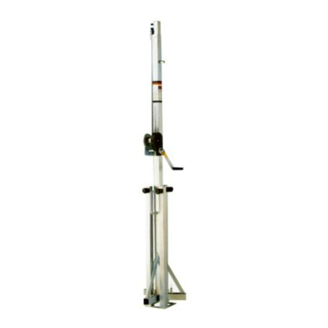
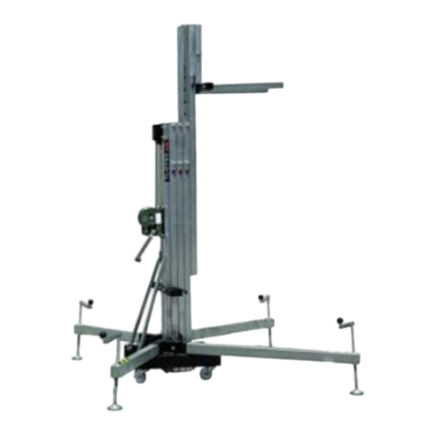
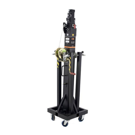
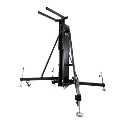
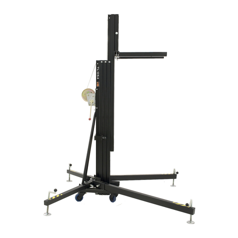
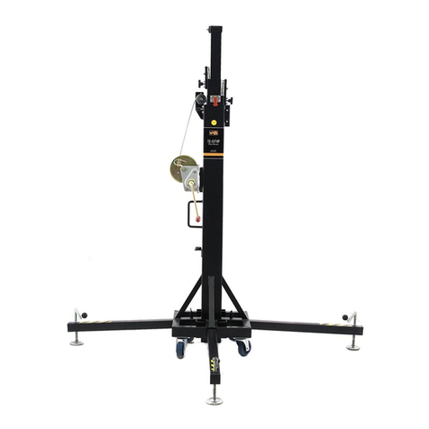
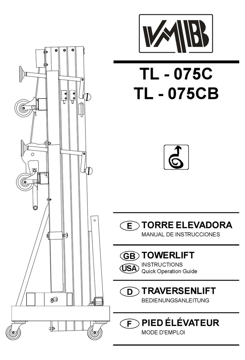
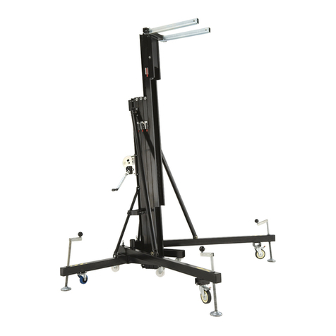
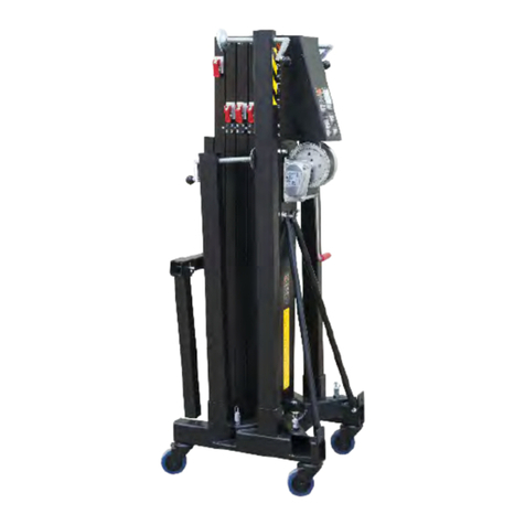
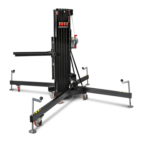
VMB TL-072 User guide

ETORREELEVADORA
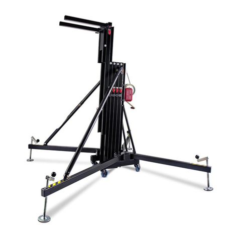
MANUALDEINSTRUCCIONES
TOWERLIFT
INSTRUCTIONS
QuickOperation Guide
GB
USA
TL -072
TL -072B
DTRAVERSENLIFT
BEDIENUNGSANLEITUNG
FPIEDÉLÉVATEUR
MODED'EMPLOI

Fabricante-Manufacturer-Hersteller-Fabricant
VMBEspañolaS.A.
Calle2-Pol. Ind.Picassent
E-46220 Picassent (VALENCIA)SPAIN
www.vmb.es -e-mail: contact@vmb.es
TORREELEVADORA
TOWERLIFT
TRAVERSENLIFT
PIEDÉLÉVATEUR
TL-072
TL-072B
EstemanualdeusuarioycatálogoanexodepiezasderepuestoespropiedaddeVMBEspañola,S.A. Queda
prohibidasureproducciontotaloparcialporcualquiermedioquelatecnologíaactualpermita.
DepósitolegalyCopyright2006.Todoslosderechosreservados.

DepósitolegalyCopyright2006.Todoslosderechosreservados.
V
P
Q
H
T
R
J
S
TL-072
W
N1
N2
ALS
C
B
F

DepósitolegalyCopyright2006.Todoslosderechosreservados.
Manual deinstrucciones ESPAÑOL
CONTENIDO
1. Introducción
2. Datostécnicos
3. Normasde seguridad
4. Instruccionesde uso
5.Mantenimiento
6. Garantia
7. Certificaciones
1.INTRODUCCION
Estimado usuario,
Lea atentamenteestemanual.
Observelosdatostécnicosysiga lasnormas
de seguridad antesde utilizarlatorreeleva-
dora.
LoselevadoresVMBsonsometidosa
durísimaspruebasparagarantizarlamáxima
fiabilidad yresistencia.La torreTL-072 está
especialmenteconcebidaparatrabajarcon
totalfiabilidad yseguridad.Sumecanismode
elevación incorporaelsistemade seguridad
ALS «Auto-Lock Security»exclusivodeVMB.
Estemanualdeberáestardisponible
permanentementejuntoalatorreelevadora.
Encasodenecesitarpiezasderepuesto,
diríjaseasudistribuidorhabitual.Solamente
deben utilizarsepiezasde repuestoorigina-
les.Elusuarioperderátodossusderechos
de garantíasiincorporacualquierrepuesto
que no sea originalorealizacualquiermodifi-
cación en latorre.
Paracualquierconsultasobrelatorredeberá
indicarelnúmerode serieyaño de construc-
ción.
2.DATOSTECNICOS
2.1- TorreelevadoramodeloTL-072
2.2- Diseñada para levantarcargasdesde
elmismosueloen sentido verticalacualquier
alturahasta6,5m.
2.3- Carga máximaelevable: 240 Kg.
2.4- Carga mínimaelevable:Puede subiro
bajarsincarga alguna.
2.5- Alturamáxima:6,50 m.
2.6- Alturamínimade carga :0,05 m.
Alturaplegada :1,98 m.
2.7- Superficiede labase: 2,2x2,2m.
2.8- Pesode transporte: 114 Kg.
2.9- Materialdeconstrucción :Cuerpo princi-
palde cuatrotramosmáscarroelevador,en
perfildealuminioextrusionado6082-T6.Base,
patasysoportesvarios,enperfileriadeacero
según DIN 2394.Gatillosde seguridad ypo-
leasacanaladasen aceroST-37.
2.10- Exclusivosistemade fijación yseguri-
dadALS(Auto-LockSecurity),patentadopor
VMB,quefijaeimposibilitalacaídadelacarga
en todo momento.(Pat. Pen.200202230)
2.11 - Cabrestantede acción manualde 900
Kg/1000Kgde capacidad de carga máxima
con freno de discosautomático.
2.12 - Cable:Acerosegún DIN3060.Calidad
180 Kg/mm2resistentealatorsión. Diámetro
6mm.
2.13 - Platillosestabilizadoresajustablesen
laspatas,conapoyosantideslizantesde
caucho inyectado.
2.14 - Fijación de laspatascon gatillosde
seguridad.
2.15- Niveldeburbujaparaajustarlaposición
verticalde latorre.
2.16 - La base,patas,tirantes,soportede
patasyportacargas,están acabadosen
poliesternegrosatinado.Latorrepuedesumi-
nistrarsecon elcuerpo principalacabado en
aluminionaturalototalmenteen negro(B).
2.17- Ruedasdireccionablesparafacilitar
eltransportede latorreenposiciónvertical
yplegadahasta suemplazamiento de
trabajo.

DepósitolegalyCopyright2006.Todoslosderechosreservados.
Manual deinstrucciones ESPAÑOL
3. NORMASDESEGURIDAD.
3.1- ElelevadorTL-072 esuna máquina
diseñada paralaelevación de cargasen
sentido vertical,NUNCAsedebe utilizar
comoplataformaelevadorade personas.
3.2- Colocarelelevadorsóloensuperficies
durasyplanas,verificandoqueestáen
posición vertical,medianteelnivelde bur-
buja(F)situadoeneltramobase.Ajustarsi
fueranecesariocon losplatillosde apoyo
(Q),girando lamanivela(H)en elsentido
adecuado.Nuncautilicecuñasnielemen-
tosextrañosparaequilibrarelelevador.
3.5- Nosedebe sobrepasarlacapacidad
decargamáximaindicadaenlaetiquetade
característicasdelelevadoryen estema-
nualde instrucciones.
3.4- Nuncasedebe elevaruna carga sin
antesverificarqueestácorrectamente
apoyada ycentradaen lossoporteseleva-
doresadecuados,deformaqueelpesode
lacarga sóloactúe en sentido vertical.
3.3- Comprobarque laspatasestán co-
rrectamentemontadasysujetasporsus
pasadoresretenedoresde seguridad.
!
Kgs

DepósitolegalyCopyright2006.Todoslosderechosreservados.
Manual deinstrucciones ESPAÑOL
3.11 - Noutilicenuncaelelevadorsobre
ninguna superficiemóvil ovehículo.
3.6- Siexisteposibilidadde vientofuerteo
en ráfagas,coloque elelevadoren suelo
firmeyasegúrelocon laayuda de tirantes.
Nuncafijeun tirantesobreun vehículoo
cualquierotroelementoquepuedadespla-
zarse.
3.10 - Nodesplacenuncaelelevadorsise
encuentracon lacarga elevada.Noes
aconsejablerealizarningún tipo de movi-
miento,nitansiquierapequeñosajustesde
posicionamiento.
3.9- Nuncasepongadebajode lacarga ni
permitalapresenciade otraspersonasen
lazona de trabajodelelevador.
3.8- Tengacuidadocontodotipodesalien-
tesporencimadelelevadorcomocorni-
sas, balcones,letrerosluminosos,etc...
Esmuyimportanteevitarlapresenciade
cablespordebajodelaalturadetrabajodel
elevador.
3.7- Nouseescalerasencimadelelevador
nilasapoyeen élpararealizarningún tipo
de trabajo.

DepósitolegalyCopyright2006.Todoslosderechosreservados.
3.12 - Antesde utilizarelelevador,verifi-
que elestado delcable.Elcableno debe
presentarroturade hilosoaplastamiento.
NUNCAusecablesdefectuososyencaso
de duda cambieelcable.Sóloutilicecable
de acerosegúnDIN3060.Calidad180Kg/
mm2resistentealatorsión.
3.16 - Paraeltransportedelelevadorhay
que bajartodoslostramos.
3.15- Noengrasenilubriqueelmecanismo
de freno delcabrestante.Losdiscosde
freno,han sido engrasadoscon una grasa
especialresistentealcalorylapresión.No
deben serutilizadosotrosproductospara
evitarinfluirnegativamenteen elfunciona-
mientodelfreno.
3.14 - La carga mínimaparaun funciona-
mientodelfrenosinproblemasesde50Kg.
Sinestacarga mínimaelfreno no actuará.
3.13 - Nuncadesmontelamaniveladel
cabrestantesielelevadorestáconcargay
elevado.
3.17 - Solamentedeben utilizarsepiezas
de repuestooriginales.
Manual deinstrucciones ESPAÑOL
ORIGINAL
-50

DepósitolegalyCopyright2006.Todoslosderechosreservados.
4.INSTRUCCIONESDEUSO.
4.1- Coloque latorreelevadoraapoyada en
susruedasdetransporte(T)sobreunasuper-
ficieplanayfirme ensuemplazamientode
trabajo.
4.2- Saque laspatasde susoportepara
transporte(S)einsértelasafondo en sus
alojamientosdetrabajo(V)comprobandoque
quedan sujetasporlosgatillosretenedores
(R). Laspataslargasdelante, bajolacarga.
4.3- Ajustelaposición verticalde latorre
mediantelosplatillosdeapoyoregulables(Q)
girandolasmanivelasdelaspatasestabiliza-
dorasparalograrquelaburbujadelindicador
de nivel(F)quede centrada en elcírculo.
4.4- Coloquelosbrazosde cargaen posición
horizontalycoloque lospasadoresde seguri-
dad.
4.5- LACARGAMÁXIMAES DE240 Kg.
Nuncadebe sobrecargarselatorreporenci-
made sucarga máximade trabajo(240 kg).
Laseguridad detrabajoeslomásimportante.
Coloque lacarga sobrelatorremedianteun
soporteadecuado según elcaso,de forma
que elpesode lacarga sóloactúe en sentido
vertical.
4.6-Colocarlacarga
Cuando utilicebrazosde carga coloque
SIEMPRElacarga lomáscercaposiblede la
torre.La carga máximade latorreTL-072
disminuyecon ladistanciaalcuerpo de la
torre. Véasecuadrode cargasen función de
ladistanciadelcentrode aplicación de la
carga.
Manual deinstrucciones ESPAÑOL
A25 cm 240 kg
B30 cm 208 kg
C40 cm 156 kg
D50 cm 125 kg
E60 cm 104 kg
F70 cm 89 kg
G80 cm 78 kg
H90 cm 69 kg
I100 cm 62 kg
Distancia del centro
de la carga ala torre Carga máxima
elevable
Colocarlaspatasinsertadasparatrabajo.

DepósitolegalyCopyright2006.Todoslosderechosreservados.
MUYIMPORTANTE: Cuando seutilizan dos
torresparaelevarun puente,ovariastorres
paraelevaruna estructurarectangularode
cualquierotraforma,esimposibleque varias
personasaccionen loscabrestantesyeleven
obajen lastorresexactamenteporigual.En
un momentodeterminado cada torrepuede
estarsituada auna alturamuydiferentede
lasdemás.
Esnecesarioque lassujecionesde laestruc-
turapermitanlasholgurasyarticulacionesne-
cesariasparaabsorberlasdiferenciasentre
laalturade cada torre.Con una fijación rígi-
da,siladiferenciade nivelesimportante,la
fuerzadelbrazode palancagenerado forza-
rálateralmentelastorrespudiendo llegara
frenarlasademásde deformarlapropiaes-
tructurade truss.
SistemadeseguridadALS
La torreTL-072 dispone delsistemade segu-
ridad ALSautolocksecurity(gatillosrojos).
ALSesun mecanismode seguridad patenta-
do yexclusivode VMB.ElsistemaALSblo-
quea automáticamentelatorreen cualquier
posición que sedeje.Cada tramoestáase-
gurado porun gatillodelsistemaALSque blo-
quea sudeslizamientode maneraautomáti-
caimpidiendo sudescenso.
4.7- Elevación:
Soltarelpasadorde bloqueo paratransporte
(B)ygirarlamainveladelcabrestanteen el
sentido de lasagujasde un relojparaelevar
unoscentímetroselcarro.Sacarlosbrazos
decarga(C)de suposición de transporte
ycolocarlosen laposiciónde trabajo
asegurándoloscolocando lospasadores.
Girardenuevolamanivelaenelmismo
sentido.La torresedesplegaráverticalmente
elevándosehastaalcanzarlaalturadeseada.
Manual deinstrucciones ESPAÑOL
4.8- Retención:
Sueltelamaniveladelcabrestanteen cual-
quiermomentoylatorresemantendráenesa
posición porlaacción delfreno de discodel
cabrestante.Gireligeramenteensentidocon-
trariolamanivelaparacomprobarquelatorre
estábloqueada yasegurada porelsistema
ALS.LosgatillosdelsistemaALSbloquearán
automáticamentelostramosde latorreala
alturaalcanzada yelcabledejaráde soportar
lacarga.
4.9-Descenso:
Elevelacargaligeramentehastaqueelgati-
lloALS(rojo)selibere.Presioneelgatillorojo
deseguridadymanteniéndolopresionado,
girelamaniveladelcabrestantehastabajar
completamenteeltramo.Procedadelamis-
mamaneraconelsiguientetramo. Lacarga
irádescendiendotramo atramo hastaquela
torrequedecompletamenteplegadaasu
altura mínima.
Latorrepuededejarseen cualquierposición
intermediaquesenecesite delmismomodo
que alsubirlacarga.
Encasode que elgatilloestébloqueado por
lacarga,hayque subirligeramentelatorre
girandolamaniveladelcabrestanteparades-
pués,unavezliberadoelgatillo,irbajandocon
normalidad.
4.10 -Transporte:
Plieguelatorrebajandocompletamentetodos
lostramos.Una vezplegada fijeelcarro
elevadorcon elpasadorde bloqueo para
transporte(B).Desmontelaspatasliberando
losgatillosde retenciónycolóquelasen su
posición de transporte (S).Aprietelostor-
nillos(J).

DepósitolegalyCopyright2006.Todoslosderechosreservados.
5.MANTENIMIENTO.
5.1- Compruebe periódicamenteelestado
delcable.Siun cablepresentaroturade hilos
oaplastamiento,debe sersustituido inmedia-
tamenteporotronuevo.Noutilicelatorrecon
cablesen malestado.Utilicesolamentecable
de aceroDIN 3060 resistentealatorsión.
5.2- Latorreelevadorasesuministracomple-
tamenteengrasadadefábrica.Noobstante,se
recomiendaengrasarperiódicamente(según
eluso)lacoronadentadadelcabrestante,los
cojinetesdelárbolde accionamientoyelbuje,
laroscadelamanivelaylostramos.
ATENCION:Noengrasarnilubricarel
mecanismodelfreno.
Losdiscosde freno hansido engrasadoscon
unagrasaespecialresistentealcalorylapresión.
Nodebenserutilizadosotrosproductospara
evitarinfluirnegativamente enelfuncionamiento
delfreno.
5.3-LatorreelevadoraTL-072debepasaruna
inspeccióntécnicaanualcomo mínimo,enun
serviciotécnicoautorizadoVMB, paravalidar
lascertificacionescomprobandoelperfecto
estado de uso de todosycadaunode
losdiferenteselementosmecánicosque
intervienenenelfuncionamientodelatorre
elevadora.
5.4- Solamentedeben utilizarsepiezasde
repuesto originalesparagarantizaruna
continuada seguridad de uso.
Elusuariopierdetodoslosderechosde
garantíasiincorporaotrosrepuestosque no
sean originalesollevaacabocualquier
modificación en elaparato.
5.5- Parasolicitarcualquierpiezaderepuesto,
debe indicarsesunúmerode referencia,que
figuraen lashojasde despiecede este
manual.
Manual deinstrucciones ESPAÑOL
7.CERTIFICACIONES
-
Directivade maquinas:
89/392/CE y98/37/CE
-BGVC1(GUV-VC1)/BGG912(GUV-G912)
6.GARANTIA.
Elperiodode garantíade estatorreelevadora
esdedosaños,apartirdelafechadecompra.
VMBEspañola,S.A.secompromete,a
partirde estafecha yduranteelperiodo de
garantía, aeliminartodoslosfallosque
puedan aparecerproducidospordefectosde
losmaterialesode lafabricación.
Noestán incluidosen lagarantíalos
dañosproducidosporunusoindebido,
modificacionesdelproducto,manipulaciónpor
tercerososiniestronaturaloaccidental.

DepósitolegalyCopyright2006.Todoslosderechosreservados.
Quick Operation Guide ENGLISH
CONTENTS
1. Introduction.
2. Technicalinformation.
3. Howtoplacethe load
4. Howtoload structures
5. Howtoload abridge
6. Guarantee
7. Certifications
1.INTRODUCTION
Dearcustomer,
In orderto operate the towerlift TL-072in
asafe and reliablemanner,followthe
instructionsinthisbooklet.
Beforeoperating the lift, read the instructions
carefully.
Pleasenotethe technicalinformation.
Ourproductsundergo veryrigoroustesting
understrictconditionsandtheyaremonitored
continuouslyduringthemanufacturing
process.
Inorderto guaranteethe lift function and
safety,theoriginalpartsofthemanufacturer's
design mustbe used. Ifanypartsotherthan
thoseof themanufacturerareused, orthe
productis modified inanyway,the user
forfeitsall warrantyrightsto claim.
VMBreservestheright tomodifythe
productspecificationswithoutpriornotice.
The modeltype, productionyearand
serialnumbermustbequoted inany
queriesorordersforspare parts.
2.TECHNICALIINFORMATION
2.1- Towerlift TL-072.
2.2- Designedtoliftloadsverticallyto
differentheightstosupportlightingsystems.
2.3- Maximumload : 240 Kg.
2.4- Minimumload :Can be lifted withno
weight.
2.5- Maximumheight:6,5m.
2.6- Minimumheight:1,98 m.
2.7- Area ofbase: 2,2x2,2m.
2.8- Unitweight:114 Kg.
2.9- Construction material:Mainbodyin
extrudedaluminium6082-T6profile.Baseand
legsaremadeofsteelprofileaccordingtoDIN
2394.CatchesandsafetyrackofST-37steel.
2.10 - Exclusive ALS system ( Auto-Lock
Security), pat. pen.200202230.
2.11 - Winch:900/1000 Kg.ofmaximumload
withautomaticbraketostop the load.
2.12 - Cable:SteelDIN3060.Quality180 Kg/
mm2twistresistant. Cablediameter:6mm.
2.13 -Adjustablestabilizingfeetwithruber
non-slipsupports.
2.14 - Safetycatchestoanchorthe legs.
2.15 - Spiritleveltoadjustthetowervertically.
2.16 - Base,legs,supports,forksarefinished
insatinpolyester. The towercan be supplied
withnaturalaluminiumfinishorblack(version
B).
2.17 - Swivelwheelstotransportthe lift when
folded.

DepósitolegalyCopyright2006.Todoslosderechosreservados.
Quick Operation Guide ENGLISH
3. SAFETYPRECAUTIONS.
3.1- The TL-072 isamachine designed to
elevateloadsupwardsinaverticaldirection,
NEVER shouldit be used asaplatformto
elevatepeople.
3.2- Onlyplacetheliftonhard,flatsurfaces
alwayscheckingthatitisinaverticalposition
byusingthebubblelevelindicator(F)found
on the basesection.Adjustthe outrigger
stabilisers(Q)byturningthecrankstolevel
ifnecessary.NEVERusewedgesorother
foreignobjectstobringthelifttoequilibrium.
3.5- The maximumload indicated on the
characteristics labeland the instructions
manualshouldnot be exceeded
3.4- NEVERshouldthe lift be used to
elevateaload thathasnotbeen properly
checked.Itisnecessarytoverifythatthe
load iscorrectly supported and centred on
theappropriateliftsupportsothattheweight
ofthe load will only elevateinavertical
direction.
3.3- Checkthat the outriggersareplaced
and set-up correctly using the pinssafety
system.
Kgs
!

DepósitolegalyCopyright2006.Todoslosderechosreservados.
Quick Operation Guide ENGLISH
3.11- NEVERusetheliftonavehicleorany
othermobilesurface.
3.6- Ifthereisapossibilityofstrong winds
orgusts,placethe lift on the ground firmly
andsecureitwiththeuseofstraps.NEVER
attachastrap toavehicleoranyother
object thatcan possibly be moved.
3.10 - NEVERmovethe lift whilstitis
carrying aload. It isnot advisabletocarry
outanytypeofmovementevensmall
positionaladjustments.
3.9- NEVERallowanyteammemberbelow
theloadoranybodyelseintheliftsoperating
zone.
3.8- Takecarewithallobstaclesabovethe
liftanditsextensionzonesuchascornices,
balconies,and luminoussignboards.Itis
veryimportant toavoidthe presenceofall
typesofcablesbelowthe extended lift.
3.7- Donotusestepladderson the lift or
useitasasupport forthem.

DepósitolegalyCopyright2006.Todoslosderechosreservados.
3.12 - Beforeusing the lift, checkthe state
of the cable. The cableshouldnot contain
broken threadsorshowanysignsof
crushed/flattenedareas.NEVERusefaulty
cables,alwayschange themifthereisany
doubt. Only usesteelcablesreference:
DIN3060.Quality:180KG/mm and torsion
resistant.
3.16 - All sectionsmust be lowered during
transportation.
3.15- Donotgreaseorlubricatethewinch’s
breakingmechanism.Thebrakediskshave
been greased withaspecialheatand
pressureresistantsolution.Otherproducts
shouldnotbeusedtoavoidnegativeeffects
regarding the braking mechanism.
3.14- Theminimumload toavoidproblems
regardingthebreakingmechanismis50KG.
Withoutthisload the brakewill notwork.
3.13 - NEVERtakeapartthe crankofthe
winchwhen the lift iscarrying aload or
extended.
3.17-Onlyoriginalreplacementpartsshould
be used.
ORIGINAL
-50
Quick Operation Guide ENGLISH

DepósitolegalyCopyright2006.Todoslosderechosreservados.
Quick Operation Guide ENGLISH
4. USAGEINSTRUCTIONS.
4.1- Placethe lift on afirm,flatsurfaceinthe
area itistobe used supported itstransport
wheels(T).
4.2- Removetheoutriggersfromtheirtransport
supports(S)and fully insertthemintotheir
positions(V)checking thattheyarefixed by
the pins(R).
4.3- Adjustthe outriggerstabilisers(Q)by
turning the crankstolevelthe lift. Ensureit is
inaverticalposition byusing the bubblelevel
indicator(F)found on the basesection.The
bubbleshouldbe inthe centreof the circle.
4.4- Placethe forkliftsinahorizontalposition
and securethemwiththe pins.
VMBrecommendsthe SU-070 Elevation Kit
and theBS-070 ElevationKitwhichhaveboth
been especially designedforloadingand
elevating withthe TL-072.
4.5- THEMAXIMUMLOADIS240KG.The
liftshouldNEVERbeoverloaded(over240KG).
Safetyatworkisthe mostimportantelement.
Placethe load ontothe lift using an adequate
supportaccording totheneed,usesothatthe
weightoftheload will only elevateinavertical
direction.
4.6-Howto place theload
Alwaysload asclosetothe toweraspossi-
ble.The maximumload diminishesaccording
tothe distancefromthe bodyof the toweras
illustrated inthe diagrambelow.
A10 ‘‘- 25 cm 550 lb- 250 kg
B12 ‘‘- 30 cm 457 lb- 208 kg
C16 ‘‘- 40 cm 343 lb- 156 kg
D20 ‘‘- 50 cm 275 lb- 125 kg
E24 ‘‘- 60 cm 229 lb- 104 kg
F28 ‘‘- 70 cm 196 lb-89 kg
G32 ‘‘- 80 cm 171 lb-78 kg
H36 ‘‘- 90 cm 152 lb-69 kg
I40 ‘‘-100 cm 136 lb-62 kg
Load centre’s
DISTANCE
tothe lifting carriage
Maximumlifting
LOAD

DepósitolegalyCopyright2006.Todoslosderechosreservados.
CAUTION
When twotowersareused toelevateabridge
ormanytowerstoelevateastructureofany
type,itisalmostimpossiblethattwoormore
peopleco-ordinatethe wincheselevating or
lowering the loads,at exactly the samepace.
Atacertainpointeachtowerwill be extended
toaheightdifferent tothatofthe others.
Forthisreason itisnecessarythat the
subjectionsofthe structureaccountforthis
and allowforthesedifferences.Witharigid
fixation and iftheleveldifferenceissignifi-
cant, the forcegenerated fromthe handleof
the winchwill deformthe structureand apply
alateralforcetotheliftscausingthem tobreak
and block.
SecuritysystemALS
TheTL-072incorporatesthepatentedsecurity
systemALS(AutomaticLockSecurity).
ThisVMBredtriggersystem automatically
blocksthe towerinthe position itisleftin.
Eachsection ofchainhasanALSthatblocks
the section inthe unlikely eventofthe chain
breaking.
4.7- Elevation:
Turnthe winchcrankclockwiseto liftthe
carriage afewcentimeters.Releasethe forks
andplacethemintheworkingposition
inserting the pins.Turnthe crankclockwise
and the towerwill lift.
Quick Operation Guide ENGLISH
4.8- Hold:
The towercan be left inanyintermediate
position whichwouldbe necessary.Juststop
turning the handleofthe winchand leaveit.
The automaticbrakeof the winchwill blockit
and holdthe load.
4.9-Lowering:
Lift the load until the alslockbecomesfree.
Press the ALSlock(RED)inand holditthere.
Then lowersection bysection.Repeatthe
aboveprocess foreachsection until all are
completely lowered.IftheALSgetslocked,lift
theloadslightly sotheALSlockbecomesfree
and lowerasabove.
4.10 -Transport:
Forthe transport ofthe towerisnecessaryto
foldthe machine lowering completely all the
profiles.Oncethe towerlift isfolded itisvery
importanttoblockthe lifting carriage withits
transportsupport(B).Getoutthelegsleaving
the blockade on the triggersand putthemin
theirtransportlodging (S).Then press the
fastening screws.

DepósitolegalyCopyright2006.Todoslosderechosreservados.
5.MAINTENANCE.
5.1- Regularly checkthe stateofthe cable.If
thecablehasbrokenthreads,orifitshowsany
signsofcrushed/flattened areas, itshouldbe
changedandreplacedimmediately withanew
one.Donotusethe lift ifthe cablesareinbad
condition.Only usesteelcablesreference:
DIN3060 torsion resistant.
5.2- The lift issupplied fromthe factory
completely greased.However,itis
recommendedtoperiodicallygreaseaccording
touse,the gearing,the axisbearings,the
spiralof the crank,and the sections.
REMEMBER:NEVERgrease orlubricate
thebreaking mechanism.
It isnot necessarytogreasethe brake
disks. The brakediskshavebeen greased
withaspecialheatand pressureresistant
solution. Otherproductsshouldnot be used
toavoidnegativeeffectsregarding the brak-
ing mechanism.
5.3- Anexpertshouldcheckthe TL-072 at
leastonceayearaccording toitsusage.
Consult yourdistributor.
5.4- Onlyoriginalreplacementpartsshouldbe
used toguarantee continued safetyduring
usage.
The userlosesall guarantee rightsifhe/she
usesreplacement partsthatarenotoriginal
orifhe/she makesanymodification tothe
apparatus.
5.5- Toorderanyreplacementparts,the
referencenumberon the replacementparts
pagesinthismanualshouldbe indicated.
Quick Operation Guide ENGLISH
7.CERTIFICATIONS
-
EC MachineryDirective
89/392/ECC and 98/37/ECC
-BGVC1(GUV-VC1)/BGG912(GUV-G912)
6. GUARANTEE.
Ifthe during the guarantee period becauseof
poorworkmanshiporfaultymaterialsVMB
Española,S.A.will repairorreplaceit.
The guarantee period forEurope isat 2
years.
The guarantee doesnotcoverdamage
caused byimproperuse, wearand tear
unauthorisedrepairs.Theguaranteedoesnot
coverconsumablesordefectsthathaveonly
anegligibleeffecton the value oroperation of
the elevatortower.

DepósitolegalyCopyright2006.Todoslosderechosreservados.
Bedienungsanleitung DEUTSCH
Inhaltsverzeichnis
1.Einführung.
2.Technische Daten.
3.Sicherheitsmaßnahmen.
4.Bedienungsanleitung.
5.Wartung.
6.Garantie.
7.Zertifikat.
1.Einführung.
SehrgeehrteDamen und Herren,
dievorliegende Betriebsanleitung wurde mit
dem Zweck erstellt, einezuverlässige
Bedienung desTL-072 Hebeturmszu
ermöglichen. LesenSiebitte die
Betriebsanleitung vorderInbetriebnahme
sorgfältigdurch.
BittebeachtenSieauchdietechnischeDaten.
UnsereProdukte unterliegenstrengsten
Prüfungen und Kontrollen beiderFertigung.
Essind ausschließlichOriginal-Ersatzteilezu
verwenden.Fürden Anwenderwerden alle
Gewährleistungsansprüche aufgehoben,
wenn erNicht-Original-Ersatzeileverwendet
bzw.ÄnderungenamProduktselbstvormimmt.
2.Technische daten.
2.1- Hebeturm,TypTL-072.
2.2- DasGerätistzumsenkrechten Heben
von Lasten, wieBeleuchtungskörperauf
verschiede Höhen,konzipiertworden.
2.3- Zulässige Hubkraft: 240 kg.
2.4- Mindesthublast : 20 Kgs.
2.5- Zulässige Hubhöhe : 6,5m.
2.6- Mindesthöhe : 1,98 m.
2.7- Grundplattenfläche : 2,2x2,2m.
2.8- Transportgewicht:114 Kgs.
2.9- Werkstoffe:Aluminium6082-T6Profil.
Basisplatteund AuslegerausStahlprofil DIN
2349.VerschlüsseausST-37 Stahl.
2.10 - ExklusiveALSSystem
(pat, pen, 200202230 )
2.11 - DieWinde:900/1000 kg.
2.12 - Seildurchmesser:SteelDIN3060.
Qualität180 kg/mm 2
Durchmesser: 6mm
2.13 -Auslegermitverstellbaren Spindeln
und rutschfesten Gummifüßen.
2.14 -Verankerung derAuslegerüber
Sicherheitsrastbolzen.
2.15- WasserwaagezumEinstellender
senkrechten Turmlage.
2.16- KorrosionsschutzundVeredelungdurch
elektrolytische Cadmierung oder(Version B)
Satinpolyester.ErhältlichinNaturAluminium
oder.
2.17 - Transportrollenzum Bewegendes
Turmsbeisenkrechterundeingefahrener
Stellung zurArbeitsstelle.
(optionalTL–072)

DepósitolegalyCopyright2006.Todoslosderechosreservados.
3.SICHERHEITSMAßNAHMEN. !
3.1- DerTL–072 wurde konzipiertzum
Heben und Senken von vertikalen Lasten.
Nutzen SieIhn niemalszurBeförderung
von Personen.
3.2- AchtenSiedarauf,dasderTL–Tower
auffestem,geradenUntergrundsteht.Und
vergewissernSiesichmitHilfeder
Wasserwaage (F),dass ereine vertikale
Position zumBoden eingenommen hat.Bei
BedarfmittelsdesStelltellers(Q)durch
DrehenderSpindelkurbel(H)die
entsprechende Tunlage einstellen.
3.5- Diezulässige Höchstlast, dieSieauf
denTypenschild,welche sieinder
Bedienungsanleitung finden,darfniemals
überschritten werden
3.4- Niemalssollten Sieeine ungesicherte
Ladung heben. VergewissernSiesich
immer,dasdieLadung zentriertaufder
GabelaufliegtundnurinvertikalerRichtung
hebt!
3.3- VergewissernSiesich,dassdie
Auslegerrichtigeingestecktsindundnutzen
SiedieRastbolzen zumfeststellen!
Bedienungsanleitung DEUTSCH
Kgs

DepósitolegalyCopyright2006.Todoslosderechosreservados.
3.11 - Esistnichtgestattetden Lift auf
einemFahrzeugmiteinenmobilenUnterbau
zuinstallieren!
3.6- BeiFreiluftanwendungen den Turm
auffestenBoden stellen und mittels
Seilankergegen Windbelastung sichern.
NiemalsanFahrzeugendieAbspannungen
befestigenoderanGegenständen,die
ausweichen könnten.
3.10 - Bewegen Sieden Lift niemalsunter
Belastung.
3.8- Achten SieaufalleGegenstände im
oberen HubbereichdesLiftes. Achten Sie
aufBalkone,Leuchtschriftenundbesonders
aufstromführende Kabel.
3.7- Stellen SieniemalsLeiternan den
Tower.
Bedienungsanleitung DEUTSCH
3.9- Halten Siesichniemalswährend des
Hebensund SenkensinGefahrenbereich
auf.
Other manuals for TL-072
1
This manual suits for next models
1
Table of contents
Languages:
Other VMB Lifting System manuals
VMB
VMB TL-A300 Instruction Manual

VMB
VMB SMART TOWERLIFT Instruction Manual
VMB
VMB TL-A220 User manual
VMB
VMB TE-074 User manual
VMB
VMB HDT-8 User manual
VMB
VMB TL-063B Instruction Manual

VMB
VMB TL-A300 Instruction Manual
VMB
VMB TE-064PS User manual
VMB
VMB TL-A150 Instruction Manual
VMB
VMB TE-064 User manual
Popular Lifting System manuals by other brands

JLG
JLG G6-42A Replacement instructions
Space
Space SDE2250LIKA Translation of the original instructions

HALDER
HALDER M8 Short instruction manual
AAQ
AAQ AutoLift AL-162016 Installation manual & operation instructions

Presto Lifts
Presto Lifts M100 Installation, operation and service manual
CMC
CMC S28 Use and maintenance manual
