ViaLite Hxx-QS-HB-3 Series User manual

ViaLite quick start guide www.vialite.com
Hxx-QS-HB-3 VialiteHD Quick Start Guide Page 1 CR3134
PPM ViaLiteHD Quick Start Guide
This quick start guide is intended as an information summary, the relevant equipment
handbook should always be treated as the master document.
Initial Inspection
Unpack and inspect the equipment as soon as possible. If there is any sign of damage or any parts missing, do not install the equipment before seeking advice from PPM
or your local agent. The equipment received should match the delivery note that is shipped with the equipment. If there are any discrepancies, contact PPM or your
local agent.
Electrical Safety
ViaLiteHD HPS Power Supply Units are Safety Class 1 products (having metal case directly connected to earth via the power supply cable). The unit is
also fitted with an earthing/grounding stud connected to the power supply earth. When operating the equipment note the following precautions:
Hazardous voltages exist within the equipment. There are no user serviceable parts inside; the covers should only be removed by qualified technician.
The equipment does not have a mains isolating switch. Equipment must be installed within easy reach of a dual pole mains isolation switch.
There are no user replaceable fuses in the rack mounted equipment. Replacement should only be carried out by a PPM technician.
ESD Precautions
Precautions for handling electro-static sensitive devices should be observed when handling all ViaLiteHD modules. Technicians should ensure that they
use effective personal grounding (i.e. ESD wrist strap etc..) when servicing the equipment. Any equipment or tools used should be grounded to prevent
static charge buildup. Good practice should be observed at all times for reference see relevant standards.
EN 61340-5-1, “Protection of Electronic Devices from Electrostatic Phenomena – General Requirements”
Optical Safety
The ViaLiteHD RF Transmitter modules contain laser diode sources operating at nominal wavelengths of 1270nm to 1610nm.
These devices are rated as EN60825-1:1994 CLASS 1 radiation emitting devices. A class 1 laser is safe under all conditions of normal use.
When operating the equipment note the following precautions:
Never look into the end of an optical fibre directly or by reflection either with the naked eye or through an optical instrument.
Never leave equipment with radiating bare fibres –always cap the connectors.
Do not remove equipment external covers when operating.
ViaLiteHD and ViaLite Classic compatibility
The RF and optical interfaces of ViaLiteHD and ViaLite Classic are compatible. Hence it is possible for units of different types to interwork and be used to expand
existing systems. However the physical size, mounting systems and control of the units are different, so it will not be possible to mix systems in a single rack or housing.
Contact PPM for more details.
Cleaning optical connectors
Optical connectors MUST be cleaned before use. Most performance issues are due to dirty fibres.
For more details please read the cleaning instruction which accompanies the connector cleaning kit. Details can also be found on the CD supplied with your equipment.
Blindmate Optical and RF Connectors
Note that the ViaLiteHD Blindmate system will simultaneously mate electrical, RF and optical backplane connectors, so both RF and optical connectors need to be
prepared. Firstly inspect the rear Blindmating plate, ensure that the connector barrels are fitted into all RF connectors and are centrally aligned. Remove any protective
covers from the optical connectors. Fit the Blindmating plate into the appropriate slot at the rear of the rack. For module installation see the following section.
Connect the external system cables to optical and RF interfaces. External interface SMA RF connectors should only be connected with a calibrated SMA torque
spanner. External optical interface SC/APC adaptors are fitted with a sprung protective cover. To connect SC/APC optical connectors, remove the plug protective cover.
Open the adaptor sprung cover, align the connector keyway slot in the adaptor to the key of the plug. Gently push the plug into the adapter until a click is heard and the
connector locks. To disconnect, grip the body of the plug and gently pull the plug from the adaptor, replace the protective cover.
- Peel the plastic cover from an unused “N” cleaning pad.
- Hold the connector between your thumb and forefinger
Clean the connector using firm pressure by swiping in a
pendulum motion through each segment of the “N” shape,
following the diagram
- Do not swipe over the same space twice.

ViaLite quick start guide www.vialite.com
Hxx-QS-HB-3 VialiteHD Quick Start Guide Page 2 CR3134
Standard Optical Connectors and Fibres
Ensure that all mating connectors are matched types.
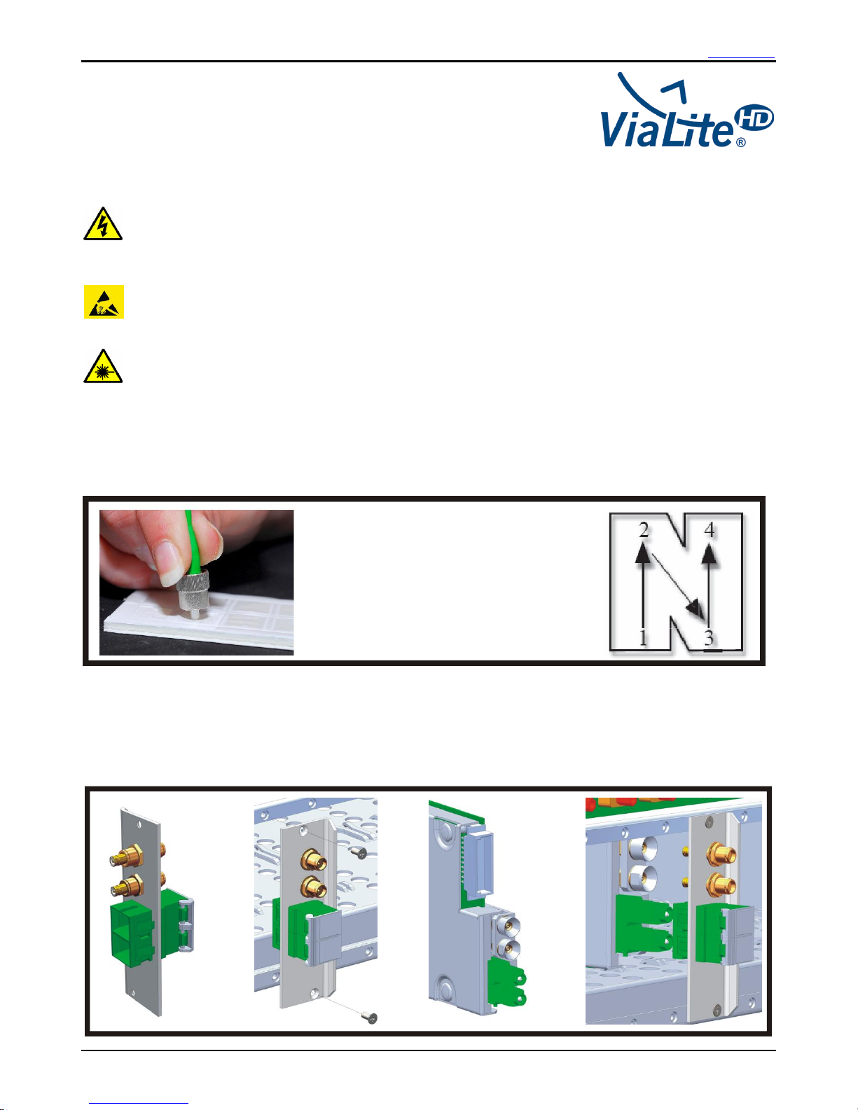
To connect SC/APC optical connectors, remove the connector protective cover. Align the connector keyway slot in the adaptor to the key of the plug. Gently push
the plug into the adapter until a click is heard and the connector locks. To disconnect, grip the body of the plug and gently pull the plug from the adaptor, replace the
protective cover.
To connect E2000/APC optical connectors. Gently push the plug into the adapter until a click is heard and the connector locks. To disconnect, depress the lever of
the plug and withdraw the connector. The protective cover engages and disengages automatically.
To connect LC/APC optical connectors, remove the connector protective cover. Gently push the plug into the adapter until a click is heard and the connector locks.
To disconnect, depress the lever of the plug and withdraw the connector, replace the protective cover.
All PPM FC/APC equipment use narrow key FC/APC connectors, these are not compatible with wide key FC/APC. To connect FC/APC optical connectors, remove
the protective cover and align the white ceramic centre ferrule on the cable connector with the mating receptacle. There is a key on the side of the ferrule, which
must match the keyway slot in the receptacle shroud. When they are aligned, gently push the plug home and finger tighten the knurled collet nut onto the threaded
receptacle. Disconnection is the reverse of connection; replace the protective covers on both the receptacle and the cable plug.
Minimum Bend Radius of a simplex patch cable is typically 30mm, at this radius there will be a very small increase in loss due to the bend (~0.05dB)
Connecting and Disconnecting RF Connectors
This product uses a range of RF connectors. Please ensure that RF connections are made with correctly matched connectors and cable impedances. Failure to do so
may result in damage to the connectors and loss of performance. SMA RF connectors should only be connected with a calibrated SMA torque spanner. BNC
connectors are available in both 50 and 75 ohms.
RF Module Input/Outputs Levels
RF inputs and outputs should not be exposed to DC voltage levels in excess of ±36V.
Absolute maximum no damage RF input level is +13dBm (some units will tolerate more, see handbook).
Absolute maximum no damage RF level applied to an RF output is +13dBm.
Some transmitter modules are pre-configured to have a DC voltage present on the RF input connector, to drive low noise amplifiers and similar equipment. Check
module handbook and description for more details. All receiver modules will create a 1-2Vpeak DC transient from the RF output at start up into a 50Ω load
(approximately 5V into a 1MΩ load). This may cause failure in some very sensitive spectrum analyzers or similar equipment. All modules have AC coupled inputs and/or
outputs and will be sensitive to large transients (>5V) applied to either input or output. This may result in permanent damage to the units, particularly to low frequency
units. Contact PPM for more details. Some receiver modules are equipped with DC loads on their outputs, please see module handbook.
19 Inch Rack Installation
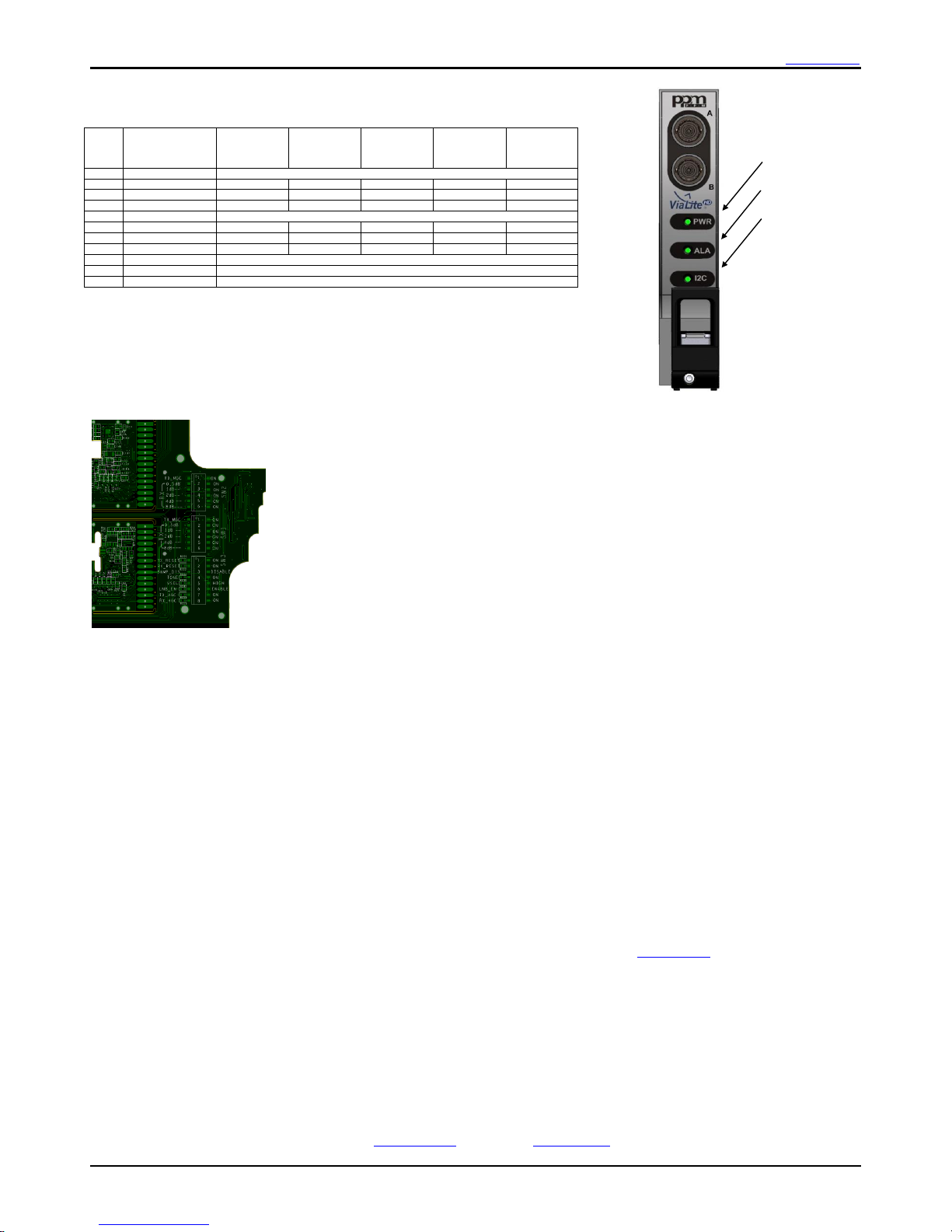
The ViaLiteHD 19” Rack Case is designed to fit 19” cabinets. Two options are available that occupy a height of either 1U or 3U; both have flanges for cabinet mounting.
The 3U rack case provides mounting for 16 modules, 13 general purpose slots (1-13), 1 dedicated controller slot (14) and 2 dedicated power supply slots (15,16). The
3U Rack Case must be used with at least one plug-in HPS Power Supply Module, power inputs are situated at the rear of the rack with one dedicated power connection
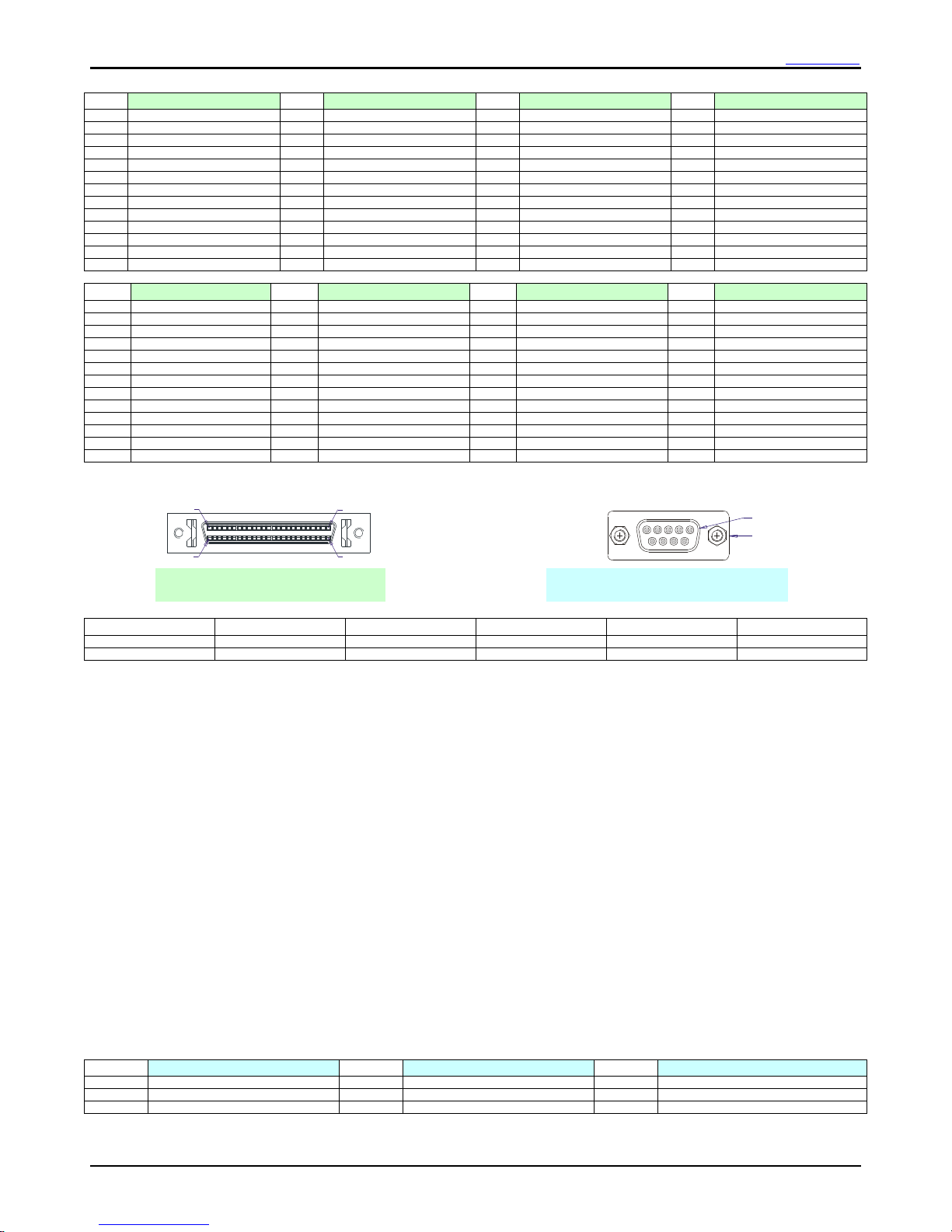
per module. The backplane contains 9-way D-type data connectors for each module position 1-13; this provides user access to module data. The rack case provides
two 50 way connectors (SCSI-3 Har-mik® female) that give access to power, alarm and rack data. The mating SCSI-3 connector can be terminated with either a ribbon
or individual round cable, contact PPM for more details. The pin-outs of these connectors are given in the following section. Either power supply position can be used;
the power supplies are designed to current share, if more than 1 is fitted. If power supplies are operating in redundant configuration, there should be a minimum load of
20 watts to ensure that both power supplies are active, below this level one power supply may be in idle mode. A dummy load board can be supplied, to fit into any of
the unused slots.
The 1U rack case provides 3 slots and 1 power supply draw. These slots can be factory configured either for 3 general purpose slots (1-3) or for 2 general purpose slots
(1-2) plus 1 controller slot (3). The 1U rack case provides two 25 way standard density D connectors that give access to power, alarm, module data and rack data. The
pin-outs of these connectors are given in the following section.
Hot swappable
modules
Slot 1-13
General Purpose
Modules
Slot 14
Controller
Module
Handle
Slots 15-16
Power Supply
Modules
Guide Pin
PSU Power Connection
IEC60320/C13
Rack Connector J1
Module Data Connector
Blindmate
Optical
Interface
Handle Release
Button
Test Port A
Test Port B
Status LED1
Status LED2
Status LED3
Rack Connector J4
Fully Enclosed Fan
Fan Power
Connector
Blindmate
Plates
Standard
Modules
Mounting flange
Blindmate
RF
Interface
Standard
Optical
Interface
Standard
RF
Interface
Controller Optical
Interface (Optional)
Controller Rear
2xRJ45 Ethernet
Interface
Controller Front
RJ45 Ethernet
Interface
PSU Status LED
Controller Craft Port
Controller Reset
Button
Removable
Fan Cassette

ViaLite quick start guide www.vialite.com
Hxx-QS-HB-3 VialiteHD Quick Start Guide Page 3 CR3134
Rack Case Summary Pinout
Pin
Rack J1*
Pin
Rack J1*
Pin
Rack J1*
Pin
Rack J1*
1
GND
14
Analogue_monitor_B_8
27
ALARM_3
40
Analogue_monitor_B_11
2
ALARM_2
15
Analogue_monitor_B_10
28
ALARM_5
41
Analogue_monitor_B_13
3
ALARM_4
16
Analogue_monitor_B_12
29
ALARM_7
42
GND
4
ALARM_6
17
GND
30
ALARM_9
43
GND
5
ALARM_8
18
GND
31
ALARM_11
44
Analogue_monitor_A_2
6
ALARM_10
19
Analogue_monitor_A_1
32
ALARM_13
45
Analogue_monitor_A_4
7
ALARM_12
20
Analogue_monitor_A_3
33
GND
46
Analogue_monitor_A_6
8
ALARM_14
21
Analogue_monitor_A_5
34
ALARM_P_1
47
Analogue_monitor_A_8
9
ALARM_P_2
22
Analogue_monitor_A_7
35
Analogue_monitor_B_1
48
Analogue_monitor_A_10
10
GND
23
Analogue_monitor_A_9
36
Analogue_monitor_B_3
49
Analogue_monitor_A_12
11
Analogue_monitor_B_2
24
Analogue_monitor_A_11
37
Analogue_monitor_B_5
50
GND
12
Analogue_monitor_B_4
25
Analogue_monitor_A_13
38
Analogue_monitor_B_7
13
Analogue_monitor_B_6
26
ALARM_1
39
Analogue_monitor_B_9
Pin
Rack J4*
Pin
Rack J4*
Pin
Rack J4*
Pin
Rack J4*
1
CSB
14
GND
27
Relay_terminal_1
40
LNA_feed_3
2
Relay_terminal_2
15
LNA_feed_2
28
GND
41
LNA_feed_5
3
GND
16
LNA_feed_4
29
GND
42
LNA_feed_7
4
GND
17
LNA_feed_6
30
GND
43
LNA_feed_9
5
GND
18
LNA_feed_8
31
+12Vdc
44
LNA_feed_11
6
+12Vdc
19
LNA_feed_10
32
+12Vdc
45
LNA_feed_13
7
+12Vdc
20
LNA_feed_12
33
+12Vdc
46
GND
8
+12Vdc
21
GND
34
+12Vdc
47
GND
9
+12Vdc
22
GND
35
+12Vdc
48
GND
10
+12Vdc
23
GND
36
+12Vdc
49
GND
11
+12Vdc
24
GND
37
+12Vdc
50
GND
12
+12Vdc
25
GND
38
LNA_feed_1
13
+12Vdc
26
Relay_terminal_3
39
GND
Note: Colour indicates relevant connector drawing
* Optional custom cable available for use in ViaLite system
The analogue monitor functions are dependent on the type of module, see below
Function
Transmitter (single)
Receiver (single)
Transceiver
Dual Transmitter
Dual Receiver
Analogue_monitor_A
Laser bias monitor
Not Used
Laser bias monitor
Laser bias monitor A
Received light level A
Analogue_monitor_B
Not Used
Received light level
Laser bias monitor B
Received light level B
Installation of Plug-in Modules
HPS power supply plug-in modules can be installed by pushing the release button of the module handle down and simultaneously pulling the top of the handle forwards.
Align the module so that the PCB slides into the “crow’s feet” with the module upright and perpendicular to the front face of the rack. Gently push the module down its
guide, applying pressure via the handle and the outmost curved face (do not apply pressure to the ventilation grill). As the module is fully mated the top of the handle
should snap back and lock in position. Addition resistance will be experienced as the low resistance backplane connector engages. The pawls of the handle should be
fully engaged in the matching slots. To disconnect the module, push the release button of the module handle down and simultaneously pull the top of the handle
forwards. Apply pressure via the handle and withdraw the module from the rack.
Blind mate modules can be installed by pushing the release button of the module handle down and simultaneously pulling the top of the handle forwards. Remove the
protective cover from the modules optical connectors. Clean the module optical connector. Align the module so that the PCB slides into the “crow’s feet” with the module
upright and perpendicular to the front face of the rack. Gently push the module down its guide, applying pressure via the handle, as the module is fully mated the top of
the handle should snap back and lock in position. The pawls of the handle should be fully engaged in the matching slots. To disconnect a module, push the release
button of the module handle down and simultaneously pull the top of the handle forwards. Applying pressure via the handle and gently withdraw the module from the
rack, replace the protective covers on the optical connectors.
Standard and controller modules can be installed by pushing the release button of the module handle down and simultaneously pulling the top of the handle forwards.
While installing the protective covers may be left in place on RF and optical connectors. Align the module so that the PCB slides into the “crow’s feet” with the module
upright and perpendicular to the front face of the rack. Gently push the module down its guide, applying pressure via the handle, as the module is fully mated the top of
the handle should snap back and lock in position. The pawls of the handle should be fully engaged in the matching slots. To disconnect a module, remove any cables
you do not want to withdraw, push the release button of the module handle down and simultaneously pull the top of the handle forwards. Applying pressure via the
handle and gently withdraw the module from the rack, replace the connector protective covers.
All ViaLiteHD plug-in modules are hot-swappable, so it is not necessary to power-down the rack case before inserting a module. It is advised that all unused slots be
fitted with blanking panels. Different width blanking panels are available; these fit the 5HP general purpose, 6HP power supply, 7HP controller card slots. They can be
used in all ViaLiteHD racks cases and will prevent accidental/unwanted access and the ingress of dust.
When operating RF fibre optic links the ideal operating input power is dependent on the end users system. However in all cases there will be the desire to achieve the
optimal signal quality (ratio of signal to noise plus distortion). At low signal power this will be dominated by thermal noise and at high signal powers it will be dominated
by distortion products. Typically a good quality signal can be obtained by operating the link at a composite input power 20dB below the fibre optic module’s P1dB
specification level (see handbooks).
The backplane has data connectors for module positions 1-13; this provides access to module data. The pin-outs of these connectors are given in the following section
Pin
Module
Pin
Rack Summary
Pin
Rack Summary
1
GND
4
TX_232_IN
7
RX_422_OUT-
2
TX_422_IN+
5
GND
8
RX_232_OUT
3
TX_422_IN-
6
RX_422_OUT+
9
RST_485
Note: Colour indicates relevant connector drawing
Connections in Blue are optional and only available on some types of module
No.1 contact
2 4-40 UNC threadx
9
1
6
5
Rack connector: View looking into connector
50 way SCSI-3 Har-mik® female
Module connector: View looking into connector
9 way D-Type connector female (DE-9)
Contact No 26
Contact No 1Contact No 25
Contact No 50

ViaLite quick start guide www.vialite.com
Hxx-QS-HB-3 VialiteHD Quick Start Guide Page 4 CR3134
Front Panel Indicators
The following table shows the operation of the front panel LEDs
Plug-in modules
Colour
Plug-in
Transmitter
(single)
Plug-in
Receiver
(single)
Plug-in
Transceiver
Plug-in
Dual
Transmitter
Plug-in
Dual
Receiver
LED1
GREEN
Normal
Flashing GREEN
Programming
Programming
Programming
Programming
Programming
RED
TX PSU fail
Not used
TX PSU fail
TXA PSU fail
RXA PSU fail
No light
Not used
RX PSU fail
RX PSU fail
TXB PSU fail
RXB PSU fail
LED2
GREEN
Normal
Flashing RED fast
TX Alarm
Not used
TX Alarm
TXA Alarm
RXA Alarm
Flashing RED slow
Not used
RX Alarm
RX Alarm
TXB Alarm
RXB Alarm
RED
Not used
Not used
All Alarm
All Alarm
All Alarm
LED3
GREEN
I2C enabled
Flashing GREEN
I2C active
AMBER
I2C disabled
Manual control The Plug-in Modules can be manually configured to set various operational parameters. The dual in line package (DIP)
switches that control these configurations are located on the bottom side of the PCB and can be accessed by withdrawing
the module by approximately a third of its length. One, two or three sets of switches will be installed dependent on the type
of module.
To enable manual gain control the TX_MGC or RX_MGC switch must be set to ON ( in some manual units the MGC may
automatically be enabled). The gain can then be decreased from a maximum (all attenuators = OFF) by changing the TX
or RX attenuator settings. The gain setting for the Transmitter or Receiver will depend on the sum of the attenuators set
(ON= gain reduced by attenuator value, OFF = no gain reduction for that attenuator). The gain can only be changed by
approximately 0.5dB steps.
Depending on configuration, some units will also allow the control of the I2C bus, VSAT power supply, LNB power, special
GPS functions and automatic gain control. More details are provided in the fibre optic module handbooks.
Quick commissioning of ViaLiteHD fibre optic link
This short commissioning procedure illustrates the processes required to install and set up a communications link with gain control.
1. Install the cards in the desired location within the rack, using the installation process as described earlier in this quick start guide.
2. Remove any dust covers from your cross site fibre (or patch leads) and the connectors on the cards (if applicable).
3. Clean the cross-site cable as described within this quick start guide.
4. Insert fibre into the connectors on the rear of the rack/card ensuring that any keyway is aligned
5. Power up the equipment (both ends of the link), all cards should have 2 GREEN LED’s and 1 AMBER LED. If any LED is RED or FLASHING RED then
check fibre connections for cleanliness and that they are correctly fitted. If this does not remover the RED LED’s then consult the full detailed manual (HRx-
HB or HRK-HB) for the comprehensive fault finding procedure
6. Connect all RF cables to the RF connectors on the rack cards.
7. Allow the equipment to warm up for 15 minutes.
8. Ensure that the RF power into the transmitter module is set to optimum for your system. Use a broadband RF power meter for this measurement. Typically
this is the input level at which the link’s intermodulation distortion (IMD) is -40dBc. This value of input power is given in the datasheet for each type of
ViaLiteHD fibre optic link.
9. Calculate the approximate optical attenuation in the fibre path. As an example, if we have two bulkhead connectors (0.2dB attenuation for each), 1500m of
optical fibre (for 1310nm laser, attenuation is 0.4dB per km) giving a total of 1dB of optical loss. The total RF gain of the system should be the nominal link
gain minus 2 x the optical loss.
10. For manually set gain control, adjust the gain via the SNMP GUI (where SNMP is fitted) or the dip switches on the card to the appropriate level required. For
automatic gain control set up AGC as shown the full system manual (HRx-HB).
11. Confirm that the RF output from the receiver is correct (to within measurement accuracy).
12. If the loss is much higher (>3dB) than expected, the most likely explanation is dirt on the optical connectors. If this is the case, clean each connection in turn
until the required system gain is restored.
ViaLiteHD user manuals
All Vialite HD user manuals are available on the CD that is shipped with each order; they can also be accessed from the www.vialite.com web site. In all cases the
handbook should always be treated as the master document.
FCC Approval
Information to the user of ViaLiteHD products
For a Class A digital device or peripheral, the following instructions are furnished to the user. This equipment has been tested and found to comply with the limits for a
Class A digital device, pursuant to part 15 of the FCC Rules. These limits are designed to provide reasonable protection against harmful interference when the
equipment is operated in a commercial environment. This equipment generates, uses, and can radiate radio frequency energy and, if not installed and used in
accordance with the instruction manual, may cause harmful interference to radio communications. Operation of this equipment in a residential area is likely to cause
harmful interference in which case the user will be required to correct the interference at his own expense.
PULSE POWER AND MEASUREMENT LTD., 65 SHRIVENHAM HUNDRED BUSINESS PARK,SWINDON,SN6 8TY, UK.
TEL:+44 1793 784389 FAX:+44 1793 784391
EMAIL:SALES@PPM.CO.UK WEBSITE :WWW.VIALITE.COM
LED1
LED2
LED3
Other ViaLite Power Supply manuals
Popular Power Supply manuals by other brands

B+K precision
B+K precision 9130 instruction manual

GarrettCom
GarrettCom Magnum IPS42 Installation and user guide

Honeywell
Honeywell 9000311PWRSPLY installation instructions

Stage Zero
Stage Zero Volta 2K user manual

Extreme Networks
Extreme Networks RPS installation guide

Selec
Selec RPS480-24-CE Operating instruction