MIL-AERO 10MHZ TO 6GHZ RF LINK HANDBOOK
3
TABLE OF CONTENTS
1INTRODUCTION ......................................................................................................................................... 5
1.1 Typical deployment.............................................................................................................................5
1.2 ViaLiteHD compatibility.......................................................................................................................5
1.3 Care of fibre optic connectors.............................................................................................................5
2SETUP AND OPERATION OF THE FIBRE OPTIC LINK........................................................................... 6
2.1 Module Type overview........................................................................................................................6
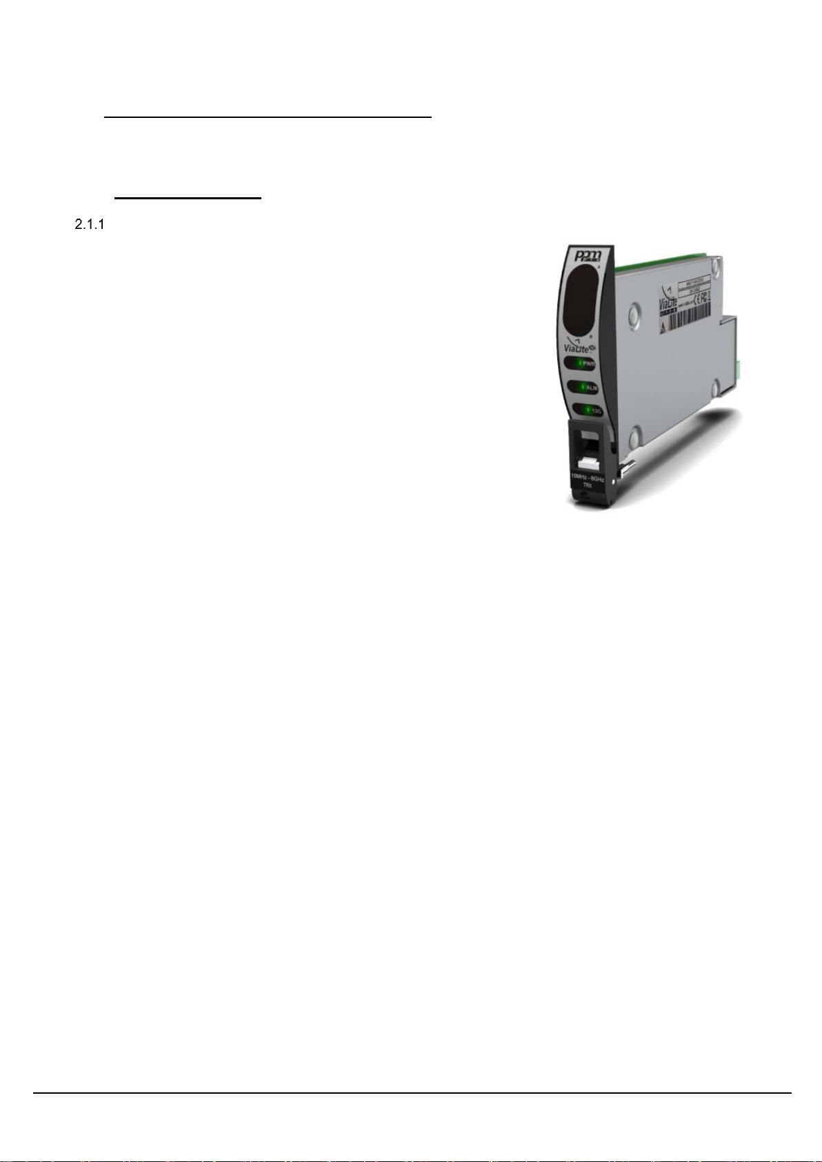
Rack card .................................................................................................................................6
Blue OEM.................................................................................................................................7
Power supply.............................................................................................................7
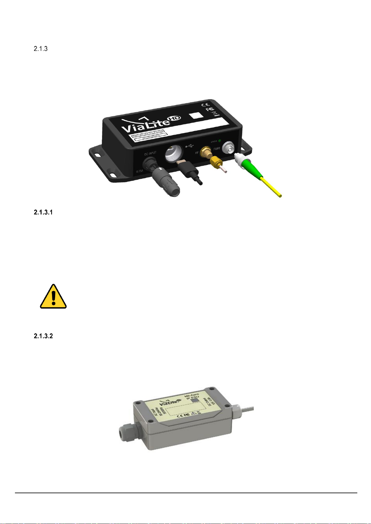
Black IP rated OEM..................................................................................................................8
Mounting and sealing................................................................................................8
Power supply.............................................................................................................8
2.2 Fibre optic interface............................................................................................................................9
Connector and cable types.......................................................................................................9
Connecting and disconnecting.................................................................................................9
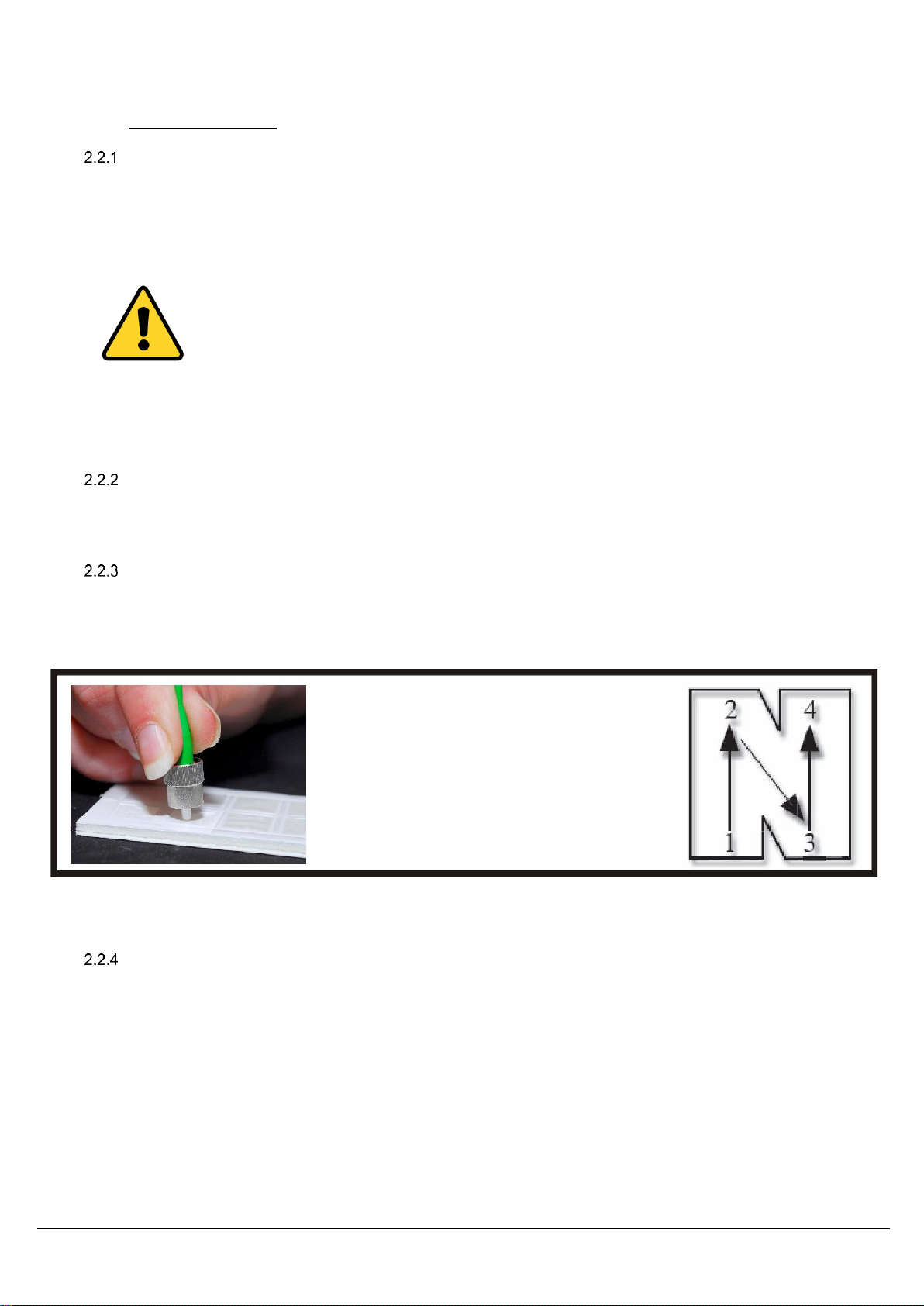
Cleaning optical connectors, cleaning before every use..........................................................9
Cleaning optical connectors, high levels of contamination ......................................................9
FC/APC Connectors...............................................................................................................10
SC/APC Connectors...............................................................................................................10
Minimum bend radius.............................................................................................................11
2.3 RF Interface......................................................................................................................................11
SMA connections ...................................................................................................................11
2.4 Front panel indicators.......................................................................................................................12
Rack card LEDs......................................................................................................................12
Blue and Black OEM LED......................................................................................................12
2.5 I/O connections and features............................................................................................................13
Analogue monitors .................................................................................................................13
RF Bias-T ...............................................................................................................................13
Active antenna failure detection (AFD) ..................................................................................14
Alarm voltage..........................................................................................................................14
Blue OEM 10 pin user connector ...........................................................................................14
Receiver RLL AGC function...................................................................................................15
2.6 Dual rack card variants.....................................................................................................................15
2.7 USB CLI command and control........................................................................................................15
Connection configuration........................................................................................................16
Command set.........................................................................................................................16
2.8 Rack card web interface via the HRC-3 ...........................................................................................17
3SYSTEM INTEGRATION........................................................................................................................... 18
3.1 Link gain ...........................................................................................................................................18
Transmitter gain......................................................................................................................18
Fibre loss................................................................................................................................18
Receiver gain..........................................................................................................................18
Gain selection for optimum link performance.........................................................................19
3.2 Frequency response.........................................................................................................................20
3.3 VSWR...............................................................................................................................................20
3.4 Noise Figure .....................................................................................................................................20
Noise figure vs link loss..........................................................................................................20
3.5 P1dB Compression...........................................................................................................................21
3.6 IP3 Linearity......................................................................................................................................21
3.7 Spurious Free Dynamic Range (SFDR)...........................................................................................21
SFDR vs link loss ...................................................................................................................21
3.8 Link delay..........................................................................................................................................22
3.9 Deviation from linear phase..............................................................................................................22