VIAVAC CB4 User manual

MANUAL VIAVAC CB4 / 4.1 Art. nr. 50504 EN (01-07-2017)
__________________________________________________________________________________________
INSTRUCTION MANUAL
Battery powered below the hook vacuum lifting device
for sandwich roof- and wall panels
__________________________________________________________________________________________
__________________________________________________________________________________________
Read this manual carefully before operating this lifter.

MANUAL VIAVAC-CB4 / 4.1 ( General section ) Art. nr. 50504 EN (01-07-2017)
__________________________________________________________________________________________
2
___________________________________________________________________________________
Index
A 1 Introduction................................................................................................................................................3
A 2 EC-declaration of conformity .....................................................................................................................5
A 3 Definitions ..................................................................................................................................................6
B 1 Operators declaration ................................................................................................................................1
B 2 Operating limits..........................................................................................................................................2
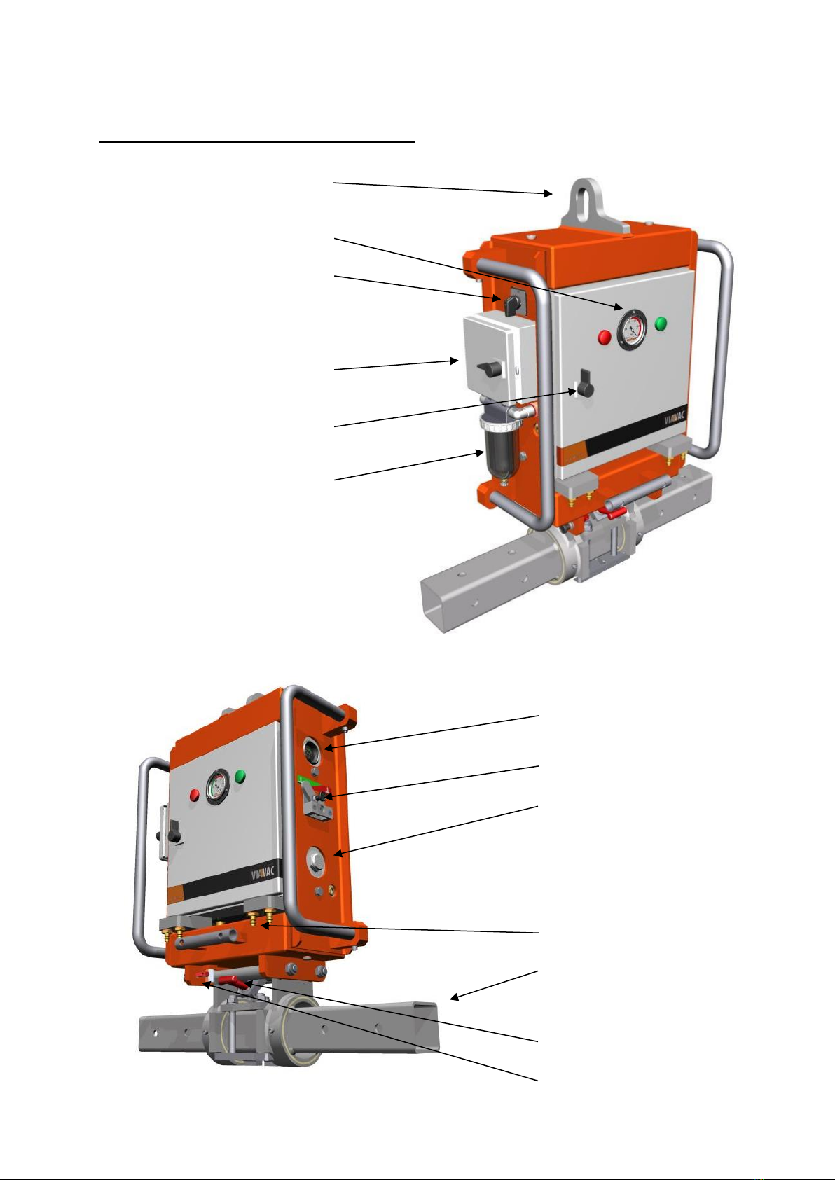
B 3 Operation ...................................................................................................................................................3
B 4 Storage........................................................................................................................................................7
B 5 Battery........................................................................................................................................................8
B 6 Transport- and manipulation possibilities..................................................................................................9
B 7 Options .....................................................................................................................................................21
B 8 Safety precautions....................................................................................................................................27
C 1 Expert declaration ......................................................................................................................................1
C 2 Technical data.............................................................................................................................................2
C 3 Checking and maintenance ........................................................................................................................3
C 4 Inspection & maintenance report ..............................................................................................................6
C 5 Fitting sealing profile in suction pad ..........................................................................................................8
C 6 Mal functioning and repair.........................................................................................................................9
C 7 Electric diagram........................................................................................................................................10
C 8 Vacuum diagram.......................................................................................................................................19
C 9 Digital vacuum switch...............................................................................................................................20
C 10 Spare parts................................................................................................................................................21
C 11 Maintenance record.................................................................................................................................33
C 12 Erradata....................................................................................................................................................35

MANUAL VIAVAC-CB4 / 4.1 ( General section ) Art. nr. 50504 EN (01-07-2017)
__________________________________________________________________________________________
3
___________________________________________________________________________________
TIP:
Gives suggestions and advice to perform certain tasks in an easier and more effective way.
TAKE CARE
a remark with additional information, draws your attention for possible problems.
WARNING
If these instructions are not carefully being executed, this can result in (serious) injuries or
even death.
A 1 Introduction
Dear reader,
This manual is subdivided in the following sections:
A General section
This section is intended for anyone who uses this manual.
B Operators section
This section is intended for anyone who utilizes and operates this device.
C Technical section
This section is intended for the specialist staff who take care for maintenance and repair of this device.
Depending your function you need to read carefully the belonging section.
To operate this device safely it is important that you strictly follow the instructions.
If you are in doubt, or face problems when use, maintenance or repair, please contact your authorized VIAVAC
dealer. They will do their utmost to serve you in an adequate and quick way.
In the text of this manual the following symbols are used.
These symbols indicate important information.
You need to be convinced that anyone who utilises this device has understood this information well.
This manual should be made available to anyone who operates, checks or repairs this device.
To have the manual available it should be stored at the designated spot together with the device.

MANUAL VIAVAC-CB4 / 4.1 ( General section ) Art. nr. 50504 EN (01-07-2017)
__________________________________________________________________________________________
4
___________________________________________________________________________________
REMARK
In this manual there are 2 versions of the VIAVAC-CB being described, namely:
CB 4 : Manual operated “Suction and release” by ball valve on the main unit.
CB 4.1 : Remote control operation “Suction and release” is possible because of electric valve on the
main unit .
Optional there are 2 type of remote control can be installed.
1. Remote control box, connected with electric cable to the main unit.
2. Radio Remote control, by transmitter and a built in receiver in the main unit.
These versions differ only concerning operation suction and release..
Where applicable, it will be indicated which version it concerns by marking (CB4) or (CB 4.1).
What is your version is indicated on the identification plate which is attached to the device.

MANUAL VIAVAC-CB4 / 4.1 ( General section ) Art. nr. 50504 EN (01-07-2017)
__________________________________________________________________________________________
5
___________________________________________________________________________________
A 2 EC-declaration of conformity
Complies to enclosure II A from directive 2006/42/EG
The manufacturer:
VIAVAC vacuum lifting BV
Bedrijfsweg 6
3411 NV Lopik
The Netherlands
Hereby declares that:
Machine : Vacuum lifter
Type : VIAVAC CB . . . . . . . . .
Machine nr. : . . . . . . . . . . . . .
Complies with the following standards and directives:
•Machine directive 2006/42/EG with alterations
•Low voltage directive 2014/35/EU
•EMC directive 2014/30/EU
•American standard ASME B30.20-2010
•American standard ASME BTH1-2011 design category “A”, Service Class “0”
•Australian Standard AS 4991-2004
The following European standards have been applied:
Safety of machinery Basic concepts EN-ISO 12100-1
Safety of machinery Basic design principles EN-ISO 12100-2
Safety of machinery Principles of risk assessment EN-ISO 14121
Safety of machinery Audible and visual warning signals EN 981+A1
Safety of machinery Electrical equipment for machines EN 60204-1:2001
Crane safety Non-fixed load lifting attachments EN 13155+A2
Date: . . . . . - . . . . . - . . . . . . . . . Signature
Arie de Groot

MANUAL VIAVAC-CB4 / 4.1 ( General section ) Art. nr. 50504 EN (01-07-2017)
__________________________________________________________________________________________
6
___________________________________________________________________________________
Managing director
A 3 Definitions
Operator Person or persons who operate and utilizes the vacuum lifter.
Lifting device Lifting crane, overhead crane, forklift truck or any other, well or not into a machine integrated
lifting arrangement, where the vacuum lifter is suspended on and lifting tasks are being
executed.
Load The object being transported and/or handled by the vacuum lifter.
Working load
Limit The maximum weight of the load which can be transported safely with the vacuum lifter
Suction By actuating a valve, sucking the load fixed to the suction pad.
Aerating By actuating a valve, releasing the load by enabling air flowing to the suction pad
Maintenance
expert Expert who is responsible for inspection, maintenance and repair of the vacuum lifting device.
Load ratio Ratio between the maximum calculated load which can be lifted with the device and the safe
working load which is indicated on the device.
Testing ratio Ratio between the load, used for the static test of the vacuum lifter and the safe working load
indicated on the device
Static
test Test where the vacuum lifter should withstand a static force equivalent to 2x working load
limit without permanent deformation and after removal of the force, there shall be no visible
defects.
Holding time
Test With the suction pad in vertical position, a (non porous) load corresponding the working load
limit is lifted. After this, the main switch is switched off so the vacuum pump will not run
anymore. The vacuum lifter should be able to hold the load for a prescribed time.

MANUAL VIAVAC-CB4 / 4.1 ( Operator section ) Art. nr. 50504 EN (01-07-2017)
__________________________________________________________________________________________
1
___________________________________________________________________________________
B 1 Operators declaration
The undersigned hereby declares that before operating this vacuum lifter, he has read and understood the
operators section of this instruction manual and will follow the instructions and guidelines.
Control of the management on compliance is required.
DATE NAME SIGNATURE
. . . . . . . . . . . . . . . . . . . . . . . . . . . . . . . . . . . . . . . . . . . . .
. . . . . . . . . . . . . . . . . . . . . . . . . . . . . . . . . . . . . . . . . . . . .
. . . . . . . . . . . . . . . . . . . . . . . . . . . . . . . . . . . . . . . . . . . . .
. . . . . . . . . . . . . . . . . . . . . . . . . . . . . . . . . . . . . . . . . . . . .
. . . . . . . . . . . . . . . . . . . . . . . . . . . . . . . . . . . . . . . . . . . . .
. . . . . . . . . . . . . . . . . . . . . . . . . . . . . . . . . . . . . . . . . . . . .
. . . . . . . . . . . . . . . . . . . . . . . . . . . . . . . . . . . . . . . . . . . . .
. . . . . . . . . . . . . . . . . . . . . . . . . . . . . . . . . . . . . . . . . . . . .
. . . . . . . . . . . . . . . . . . . . . . . . . . . . . . . . . . . . . . . . . . . . .

MANUAL VIAVAC-CB4 / 4.1 ( Operator section ) Art. nr. 50504 EN (01-07-2017)
__________________________________________________________________________________________
2
___________________________________________________________________________________
B 2 Operating limits
Lifting capacity max. 800kg, but actual S.W.L depends of the total lifting capacity of the active
suction pads required for the job specific configuration.
Own weight c.a. 100kg
Load Steel faced composite roof and wall panels. It may also be possible to lift other non
porous materials but it is recommended that test lifts are performed.
The suction area may be flat as slightly structured.
The suction pad seal can compensate (when not too rough) unevenness’s up to 5mm.
Capabilities - 90otilting from horizontal to vertical with locking facility in vertical position.
Operation elevation Max. 1.200 m. above sea level (if higher, settings vacuum switch needs to be adapted).
Operating
Temperatures 0oC to +40oC
-10oC to 0oC with special precautions.
Service life At least 20.000 cycles 10 years, when properly maintained and used as intended.
Outside use This lifter can also be used outside, however not in area with explosive danger.
Rain and snow This lifter may also be used in rain and snow conditions, however there should be
taken care that excessive water, snow and ice is removed from the suction area.
Water or ice strongly reduces the necessary friction between suction pad and load.
This friction is essential to lift the load in vertical position of the suction pad.
Wind Do not use this lifter at wind speeds above 11 meter/sec.
The maximum wind speed will reduce as panels get longer.
See wind speed tables per machine configuration.
Non rigid plates This lifter is not suitable to lift non rigid plates.
( plate can peal of from the suction pad causing to release the load.
Extra regulations according CE standard EN 13155
When this lifter is being used for the erection, renovation or demolishing of buildings
or other building constructions, the use of a falling safety device is required.

MANUAL VIAVAC-CB4 / 4.1 ( Operator section ) Art. nr. 50504 EN (01-07-2017)
__________________________________________________________________________________________
3
___________________________________________________________________________________
B 3 Operation
CB 4 Vacuum unit with handle “suction / release”
Lifting lug ( 1 )
Vacuum indicator ( 2 )
Main switch ( 3 )
Storage box ( 4 )
Cable battery charger
Button ( 5 )
Open / close
Filter / water seperator ( 6 )
( 7 ) Volt indicator
( 8 ) Handle “suction / release”
( 9 ) Acoustic warner
( 10 ) Vacuum connections
( 11 ) Tiltable main traverse
( 12 Securing handle tilting
( 13 ) Water-drain valve

MANUAL VIAVAC-CB4 / 4.1 ( Operator section ) Art. nr. 50504 EN (01-07-2017)
__________________________________________________________________________________________
4
___________________________________________________________________________________
CB 4.1 Vacuum unit prepared for optional remote control
The CB 4.1. is identical to the CB4 exept for the following:
- To permit remote control, the hand actuated valve is replaced by electro magnetic 3/2 valves.
- 3 buttons on the front door for suction (1 green) and release (2 red buttons).
- Connector to fit additional remote control on cable.
Buttons for control Connector for additional
suction & release remote control box on cable
__________________________________________________________________________________
Cable remote control
This can easily be installed by simply connecting the connector at the side of the device.
( 24 )
( 22 )
( 21 )
( 23 )
Magnets
__________________________________________________________________________________
Radio Remote Control
For this, a receiver box has is installed into the switchbox.
Suction and release can be activated on the transmitter.
( 26 )
Receiver ( 25 )
Transmitter

MANUAL VIAVAC-CB4 / 4.1 ( Operator section ) Art. nr. 50504 EN (01-07-2017)
__________________________________________________________________________________________
5
___________________________________________________________________________________
Operation procedure CB4
1. Suspend device at the crane hook by the lifting eye (1).
2. Before every lift, check the condition of the rubber sealing profile of the suction pad, there may be no
tears or damage to it.
3. Before every lift, check the black rubber back plate at the backside of the suction cups; these must be
clean and free from oil, grease or water drops.
4. Before every lift check that all locking pins are in place and secured.
5. Ensure that the control lever (8) "suction & aerating" is set to the back (read area)
Start up the device by setting the main switch (3) on 1.
-Now you will hear the vacuum pump running, it will stop 10 seconds after a vacuum level of -0.65 bar has
been built up in the vacuum buffer tank.
- The alarm is audible and the red lamp will light up as long as the vacuum level is still below -0.6-bar,
above that the alarm will stop and the green lamp will light up instead of the red one.
6. Check on the volt meter (7) whether the battery has been sufficiently charged; the pointer must remain
between the 11 and 13 volt while the vacuum pump is running.
7. Use the control lever (12) to set the suction pad in the right position.
- Lever up: enables to rotate the main traverse with 90o.
8. Put the device with the suction pad on the load, ensure that the suction surface is dry and clean.
9. Set the control lever (8) at suction (green area).
10. Check on the vacuum meter (2) whether the required vacuum level of >-0.60 bar has been built up
(pointer in the green area).
11. If used on the building site in the EU, lift the load a little and attach the fall safety straps as
indicated.
12. The load can now be lifted further and, just before the load is set on its place, the falling safety strap
should be removed, if applicable.
13. When the load has been put on its place and is secured, set the control lever (8) at aerating (red area).
14. The suction pad will release and then a new load can be taken up by putting the suction pad on it and
putting the control lever (8) at “suction”.
15. After the last element has been placed, disconnect the device by setting the main switch (3) on 0.
Operation procedure CB4.1 with cable remote control
This is identical to CB4 execpt for at the following points:
5. Ensure that the device is set to “release” bij pressing simoultaniously the 2 red buttons (21 or 22).
9. Set the device to “suction”by pressing the green button (23 or 24).
13. When the load has been put on its place and is secured, set the device on “release” by simoultaniously
pressing the 2 red buttons (21 or 22).
14. A new load can be picked up ”by pressing the green button (23 or 24).
Operation procedure CB4.1 with radio remote control
This is identical to CB4 execpt for at the following points:
For safety reasons, a code on the transmitter has to be pressed first before it is possible to activate
“suction & release”.
5. Ensure that the device is set to “release” bij pressing simoultaniously the 2 red buttons (21 or 25).
9. Set the device to “suction”by pressing the green button (23 or 26).
13. When the load has been put on its place and is secured, set the device on “release” by simoultaniously
pressing the 2 red buttons (21 or 22).
14. A new load can be picked up ”by pressing the green button (23 or 24).

MANUAL VIAVAC-CB4 / 4.1 ( Operator section ) Art. nr. 50504 EN (01-07-2017)
__________________________________________________________________________________________
6
___________________________________________________________________________________
Before any lift, the user must check the following:
I. Check the rubber sealing profile of the suction pad for damage and cracks, replace if necessary.
II Check rubber back plate of the suction pad to verify whether it is clean and free from grease, oil or
water drops and, if necessary, to clean it up.
III Whether the battery is sufficiently charged; The volt meter (8) must indicate between 11 and 13 Volt.
IV Functioning of the acoustic alarm (11) at a vacuum level below -0.60m bar.
This can be checked by briefly putting the control lever (8) in the position “suction” (green area)
before the suction pad is placed on the load.
Remove excessive water, snow and ice at the area where suction pads are placed on load.
This is essential to have suffucient friction needed for lifting in vertical or inclined position.
If the load has a protective film, it must first be removed before the suction pad is placed on the
load.
During every lift the operator must constantly monitor the following:
a. Vacuum meter, during lifting the pointer must constantly remain in the green area.
b. Acoustic alarm signal; during the lift it may not be audible.
If the vacuum meter is in the red area and/or the acoustic alarm signal sounds, do not lift!
If the vacuum meter is in the read area and/or the acoustic alarm signal sounds, a lifted load must be
put down as quickly as possible.
If the vacuum pump for some reason fails, from the moment the vacuum level
decreases below the required level of> -0.60, the load will be held for a minimum of 5 minutes.
To work safely with the device, it is therefore necessary that:
-The operator must have good hearing and is not using hearing protection.
-During the lifting the operator must be within hearing and visibility distance of the device.
- The ambient sound does not amount to more than 70db.
- The operator of the device is constantly in contact with the operator of the lifting machine and
agreements have been made about a clear communication.
Protective precautions at operation temperatures between the -10oC and 0oC.
-To prevent clogging of the filters, it has to be ensured that all the humidity has been removed from the
device. This is achieved by letting the vacuum pump run approx. 15 minutes with the control level (9) in
the position “suction” in a dry and heated compartment.
- To be assured of sufficient battery capacity, store the device at a temperature of 15oC or higher at night.
- For sufficient friction between suction pad and the load, it must be ensured for every lift that both the
suction pad and the suction surface of the load, all water, snow and ice is removed.

MANUAL VIAVAC-CB4 / 4.1 ( Operator section ) Art. nr. 50504 EN (01-07-2017)
__________________________________________________________________________________________
7
___________________________________________________________________________________
Adjustments needed when working at altitudes above 1200mtr from seal level.
The reduced atmospheric pressure at high altitudes affects the vacuum switch which controls
switching on and off of the vacuum pump and the alarm.
Depending on the altitude the settings of the switch needs needs to be adapted.
Procedure and required settings can be obtained from VIAVAC when needed.
The vacuum pump can run approx. 120 minutes constantly with a fully charged battery.
To ensure that it is possible to work a whole day with a battery load, the user must also keep an eye
on the vacuum condition of the system during the operation:
This is done by checking that the vacuum pump stops 10 seconds after a vacuum level of 0.65 bar has
been reached. Then it must take at least 30 seconds before it starts pumping again.
If the pump starts up more frequently, this indicates a leak and this causes the battery to discharge
faster than expected and one cannot operate for a whole day.
Therefore it is advisable to first rectify this, before the work is continued.
Reduced lifting capacity at higher altitudes
Lifting capacity of the suction pads are set at 500m altitude at an atmospheric pressure of 950mbar.
With increase of height, atmospheric pressure reduces and so does lifting capacity.
This reduction has to be taken into account when lifting at altitudes above 500meter from sea level.
Altitude (meter) Atmospheric pressure (mbar) Lifting capacity
0 . . . 500 1050 . . . 950 100%
501 . . . 1000 949 . . . 900 95%
1001 . . . 1500 899 . . . 850 90%
1501 . . . 2000 849 . . . 800 85%
2001 . . . 2500 799 . . . 750 80%
2501 . . . 3000 749 . . . 700 75%
Rated lifting capacity on suction pads is calculated with
- most unflavourable (-vertical) position of suction pad
- vacuum level of -600 mbar
- safety factor of 2
B 4 Storage
The device should be stored as follows:
Overnight at job site:
- keep the unit in a dry and above 00C secure place.
Long time storage when out of use :
- In a dry place at temperatures between 15 and 25oC.
- Switched off, water drained, charged battery and suction pad shielded.

MANUAL VIAVAC-CB4 / 4.1 ( Operator section ) Art. nr. 50504 EN (01-07-2017)
__________________________________________________________________________________________
8
___________________________________________________________________________________
B 5Battery
The battery can be charged by the battery charger, which is placed in the switchbox.
( 1 ) Mainswitch
( 2 ) Plug of the battery charger
( 3 ) LED lamp
- Turn the main switch (1) off.
- Insert the plug of the charger (2) in the socket,
the voltage of the mains should be between 110 ... 240V.
- The LED lamp changes during the load cycle from red (empty battery) to yellow (almost fully charged battery)
to green (fully charged battery).
In approx. 6 hours loading time an empty battery (13) is again fully charged (green LED lamp is lighted).
A full battery load is sufficient for placing a minimum of 120 elements (approx. 1 full day of operation).
When the green LED lamp is lighted, the battery charger will automatically switch to maintenance loading. The
connector can therefore remain in the electric socket without any danger of overloading the battery.
In case of a charged battery the volt meter on the cabinet indicates between 12 ... 14 Volt, when the vacuum
pump runs, it will fall back with approx. 1V.
If the meter falls back significantly to back with 2 or more Volt during additional pumping, this means that the
battery is discharged.
In case of a discharged battery the vacuum pump will also run slower, due to which it will not achieve the set
switch off vacuum level and the vacuum pump will run constantly.
If the voltage of the battery decreases below the 11V, the electronic vacuum switch will also turn off, because
of this, the vacuum pump will run constantly, the red lamp will light up and the acoustic alarm signal will
sound.
The battery will last approx. 3 to 5 years, because the capacity will decrease after time, we advise to renew the
battery every 3 years as a precaution.
It improves the life time of the battery when it is stored in a charged state.
We recommend that, even if you don’t need the device the next day, to charge immediately after use.
Interim charging the battery has no negative impact on it’s capacity (no memory effect).

MANUAL VIAVAC-CB4 / 4.1 ( Operator section ) Art. nr. 50504 EN (01-07-2017)
__________________________________________________________________________________________
9
___________________________________________________________________________________
B 6Transport- and manipulation possibilities
TYPE SANDWICH ROOF PANELS
type RA (1)
0,5 .. 0.7mm Steel / aluminium
PUR / EPS
0,4 .. 0.7mm Staal / aluminium
type RB (2)
0,5 .. 0.7mm Steel / aluminium
PUR / EPS
Foil
type RB (3)
0,5 .. 0.7mm Steel / aluminium
Mineral wool
0,4 .. 0.7mm Steel / aluminium
type RB (4)
0,5 .. 0.7mm Steel / aluminium
PUR / EPS
0,4 .. 0.7mm Steel / aluminium

MANUAL VIAVAC-CB4 / 4.1 ( Operator section ) Art. nr. 50504 EN (01-07-2017)
__________________________________________________________________________________________
10
___________________________________________________________________________________
CB4 configuration type: R2600, R4400, R6200
For roof panels up to 16 meter length
Roof pitch 0 . . . . 25o
* = Other type of suction pads on request.
. . . *= load with 4x75kg pads, ( . . . ) = max. possible load on traverse.
Type RA = roof panels with min.0,5mm steel skin & EPS/PUR/PIR core.
Type RB = roof panels with min. 0,5mm steel skin & mineral wool core.
Max. wind speeds L = up to 12 meter 11m/s, 12 up to 16 meter 9m/s.
REMARKS
- Panels with a length up to 20 meter are possible with configuration type RC 8000 - 9800.
- Panels with a roof pitch 250 up to 450are possible with configuration RT 2600 - 4400 –6200
ITEM
QUAN.
DESCRIPTION
ART. NR
1
1
Vacuum module CB4
408500
2
2 - 4 - 6
Extension beam
408003
3
1 set
Cross traverse
408501
4
4
Suction pad 110x530, 75kg
402502*
5
1 set
Falling safety device FS4
408007
DIST.
mm
EXT.
BEAMS
qty
SET
WEIGHT
kg
MAX.
LOAD
kg
L
(type RA )
meter
L
( type RB )
meter
2600
2
180
300* (800)
3 …12
3 … 8
4400
4
215
300* (500)
12 …14
8 …10
6200
6
250
300* (300)
14 … 16
10 …12

MANUAL VIAVAC-CB4 / 4.1 ( Operator section ) Art. nr. 50504 EN (01-07-2017)
__________________________________________________________________________________________
11
___________________________________________________________________________________
CB4 configuration type: R4400-K4, R6200-K4
For roof panels up to 16 meter length
Roof pitch 0 . . . . 25o
* = Other type of suction pads on request.
. . . *= load with 4x75kg pads, ( . . . ) = max. possible load on traverse.
Type RA = roof panels with min.0,5mm steel skin & EPS/PUR/PIR core.
Type RB = roof panels with min. 0,5mm steel skin & mineral wool core.
Max. wind speeds L = up to 12 meter 11m/s, 12 up to 16 meter 9m/s.
REMARKS
- Panels with a length up to 20 meter are possible with configuration type RC 8000 - 9800.
- Panels with a roof pitch 250 up to 450are possible with configuration RT 2600 - 4400 –6200
ITEM
QUAN.
DESCRIPTION
ART. NR
1
1
Vacuum module CB4
408500
2
4 - 6
Extension beam
408003
3
1 set
Cross traverse
408501
4
4
Suction pad 110x530, 75kg
402502*
5
1 set
Falling safety device FS4
408007
6
1
Chain suspension K4
257211
DIST.
mm
EXT.
BEAMS
qty
SET
WEIGHT
kg
MAX.
LOAD
kg
L
(type RA )
meter
L
( type RB )
meter
4400
4
215
300* (800)
12 …14
8 …10
6200
6
250
300* (500)
14 … 16
10 …12

MANUAL VIAVAC-CB4 / 4.1 ( Operator section ) Art. nr. 50504 EN (01-07-2017)
__________________________________________________________________________________________
12
___________________________________________________________________________________
CB4 configuration type: R8000-K8, R9800-K8
For roof panels up to 20 meter length
Roof pitch 0 . . . . 25o
* = Other type of suction pads on request.
. . . *= load with 4x75kg pads, ( . . . ) = max. possible load on traverse.
Type RA = roof panels with min.0,5mm steel skin & PUR/PIR core.
Type RB = roof panels with min. 0,5mm steel skin & mineral wool core.
Max. wind speeds L = 16 up to 20 meter 8m/s.
REMARKS
- Panels with shorter lengths are possible with configuration type R 2600 - 4400 - 6200.
- Panels with a roof pitch 250up to 450are possible with configuration RT 2600 - 4400 –6200.
ITEM
QUAN.
DESCRIPTION
ART. NR
1
1
Vacuum module CB4
408500
2
6 - 8
Extension beam
408003
3
1 set
Cross traverse
408501
4
4
Suction pad 110x530, 75kg
402502*
5
1 set
Falling safety device FS4
408007
6
2
Bended extension beam
408004
7
1
Chain suspension K8/K10
408050
DIST.
mm.
EXT.
BEAMS
qty.
SET
WEIGHT
kg
MAX.
LOAD
kg
L
(type RA )
meter
L
( type RB )
meter
8000
8
290
300* (500)
16 … 18
Not advisable
9800
10
325
300* (500)
18 … 20
Not advisable

MANUAL VIAVAC-CB4 / 4.1 ( Operator section ) Art. nr. 50504 EN (01-07-2017)
__________________________________________________________________________________________
13
___________________________________________________________________________________
CB4 configuration type: R8000/2600-K8, R9800/2600-K8
For roof panels up to 20 meter length
Roof pitch 0 . . . . 25o
* = Other type of suction pads on request.
. . . *= load with 8x75kg pads, ( . . . ) = max. possible load on traverse.
Type RA = roof panels with min.0,5mm steel skin & PUR/PIR core.
Type RB = roof panels with min. 0,5mm steel skin & mineral wool core.
Max. wind speeds L = 16 up to 20 meter 8m/s.
REMARKS
- Panels with shorter lengths are possible with configuration type R 2600 - 4400 –6200, RC 8000 - 9800.
- Panels with a roof pitch 250up to 450are possible with configuration RT 2600 - 4400 –6200.
ITEM
QUAN.
DESCRIPTION
ART. NR
1
1
Vacuum module CB4
408500
2
8 - 10
Extension beam
408003
3
1 set
Cross traverse
408501
4
1 set
Intermediate cross traverse
408502
5
8
Suction pad 110x530, 75kg
402502*
6
2 set
Falling safety device FS4
408007
7
2
Safety strap mounting
408016
8
1
Chain suspension K8/K10
408050
DIST.
mm.
EXT.
BEAMS
qty.
SET
WEIGHT
kg
MAX.
LOAD
kg
L
(type RA )
meter
L
( type RB )
meter
8000
8
350
600* (800)
16 … 18
12 … 14
9800
10
385
600* (500)
18 … 20
14 … 16

MANUAL VIAVAC-CB4 / 4.1 ( Operator section ) Art. nr. 50504 EN (01-07-2017)
__________________________________________________________________________________________
14
___________________________________________________________________________________
CB4 configuration type: R15200/6200-K8K16, R17000/6200-K8K16
For roof panels up to 26 meter length
Roof pitch 0 . . . . 25o
* = Other type of suction pads on request.
. . . *= load with 8x75kg pads, ( . . . ) = max. possible load on traverse.
Type RA = roof panels with min.0,5mm steel skin & PUR/PIR core.
Type RB = roof panels with min. 0,5mm steel skin & mineral wool co
Max. wind speeds L = up to 20 meter 8m/s, 20 up to 26 meter 6m/s.
REMARKS
- Panels with shorter lengths are possible with configuration type R 2600 - 4400 –6200, RC 8000 - 9800.
- Panels with a roof pitch 250up to 450are possible with configuration RT 2600 - 4400 –6200.
ITEM
QUAN.
DESCRIPTION
ART. NR
1
1
Vacuum module CB4
408500
2
16 - 18
Extension beam
408003
3
1 set
Cross traverse
408501
4
1 set
Intermediate cross traverse
408502
5
8
Suction pad 110x530, 75kg
402502*
6
2 set
Falling safety device FS4
408007
7
2
Safety strap mounting
408016
8
1
Chain suspension K8K16
257210
DIST.
mm.
EXT.
BEAMS
qty.
SET
WEIGHT
kg
MAX.
LOAD
kg
L
(type RA )
meter
L
( type RB )
meter
15200
16
459
600* (500)
18 … 24
16 … 21
17000
18
530
300* (500)
20 … 26
19 … 23
This manual suits for next models
2
Table of contents
Popular Industrial Equipment manuals by other brands

matev
matev FPS JD-2026R operating manual

ITW Dynatec
ITW Dynatec DYNAMINI 4-HOSE Technical documentation

UnionSpecial
UnionSpecial BCE300PD Original instructions

Eaton
Eaton SL7-CB-D-M12A4 Instruction leaflet

Wieland
Wieland SNA 4043K operating instructions

Voltaire
Voltaire 15W/F Installation, operation and maintenance manual

Schwing
Schwing CPC III manual

Paasche Airbrush
Paasche Airbrush HB-16-2F instruction manual

Nitty-Gritty
Nitty-Gritty Inox mark operating manual

Airflow Instruments
Airflow Instruments PAN300 Series Operation and service manual

Teka
Teka LMD 501 SPA operating instructions

Kitagawa
Kitagawa TT150AE-04 instruction manual