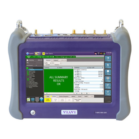
Viavi T-BERD 5800 Parts list manual
Other Viavi Network Cables manuals
Viavi
Viavi T-BERD 5800 Parts list manual

Viavi
Viavi T-BERD 5800 Parts list manual
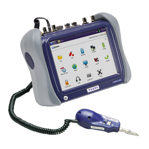
Viavi
Viavi T-BERD/MTS-5800 Parts list manual

Viavi
Viavi T-BERD 5800 Parts list manual

Viavi
Viavi T-BERD 5800 Parts list manual

Viavi
Viavi T-BERD 5800 Parts list manual

Viavi
Viavi T-BERD 5800 Parts list manual

Viavi
Viavi T-BERD 5800 User manual

Viavi
Viavi T-BERD 5800 Parts list manual

Viavi
Viavi T-BERD 5800 Parts list manual
Popular Network Cables manuals by other brands
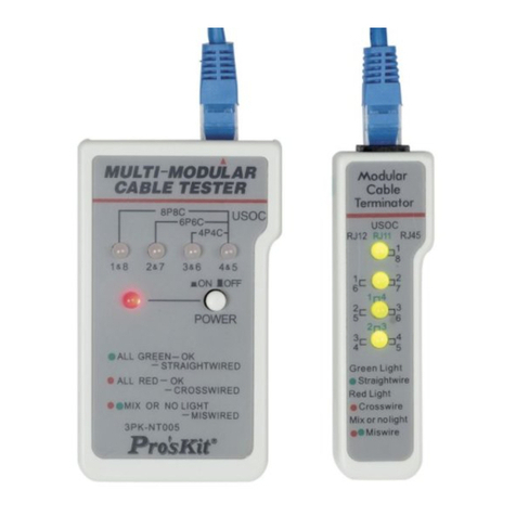
ProsKit
ProsKit 3PK-NT005 user manual
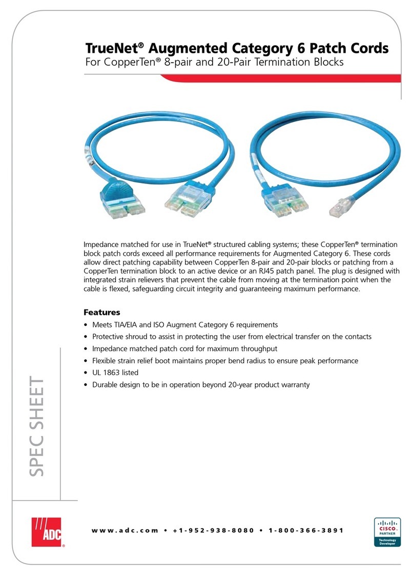
ADC
ADC TrueNet Augmented Category 6 Patch Cords Specifications

Greenlee
Greenlee GREENLEE SURE SIGNAL 46060 instruction manual
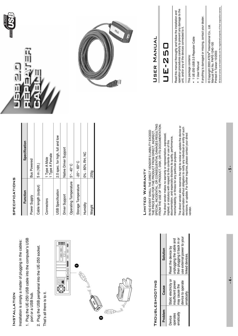
ATEN
ATEN UE-250 user manual

Schwaiger
Schwaiger NWM 1 Series Operating and safety instructions
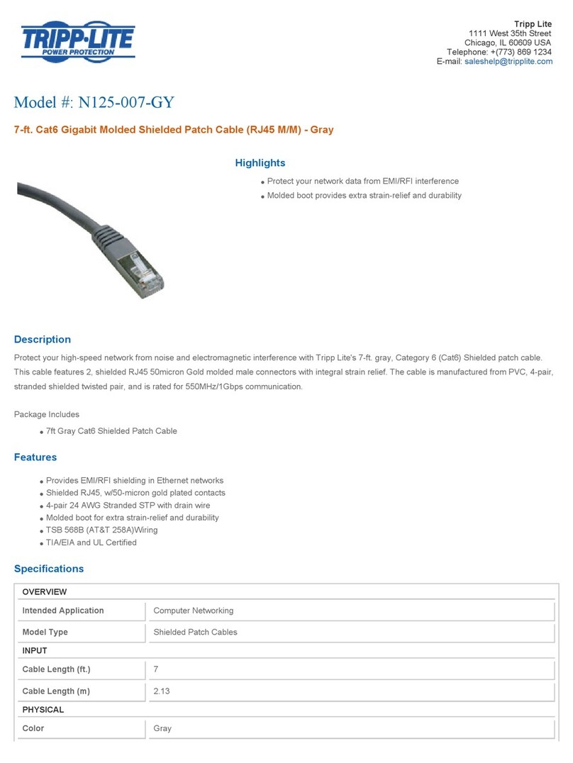
Tripp Lite
Tripp Lite N125-007-GY Specification sheet
