10
Slick Channel 5
TERMINALS AND CONNECTIONS
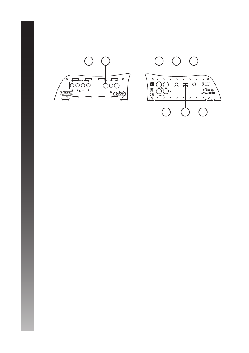
1. Low level input
For connection to any source (head unit) with a low level output. This is your RCAoutput from the
source (headunit)
2. Front gain control
This control is used to match the input signal of the source to the front amplifier channel. See the setup
section for more details.
3. Front crossover frequency control
This control is used to set the HPF crossover frequency for the front amplifier channel.
The frequency is adjustable between OFF and 200Hz.
4. Rear gain control
This control is used to match the input signal of the source to the rear amplifier channel. See the setup
section for more details.
5. Rear crossover mode select switch
This switch is used to select the crossover mode of the amplifier. FLAT is full range output, HPF is used
to limit the amout of low frequency information passed to the speakers and LPF is used to limit the
amount of high frequency information passed to the speakers.
6. Power / protect LED
If the amplifier is operating normally the green LED will illuminate.
If the amplifier is in protection mode the red LED will illuminate.
7. SUM / SUB input
This switch is used to select the input to be used for the subwoofer. SUM setting will derive a
signal from the rear channel input. The SUB setting will use a separate RCAinput such as the
subwoofer output on the source (headunit)
8. Subwoofer gain control
This control is used to match the input signal of the source to the subwoofer amplifier channel.
See the setup section for more details.
9. Subsonic filter
This control is used to set the subsonic filter which is used to limit the very low frequency
information passed to the subwoofer. The frequency is adjustable between OFF and 50Hz.
10. Crossover frequency control
This control is used to set the LPF crossover frequency for the subwoofer amplifier channel.
The frequency is adjustable between 40Hz and 200Hz.
11. Remote control input socket
Used to connect the supplied remote level control.
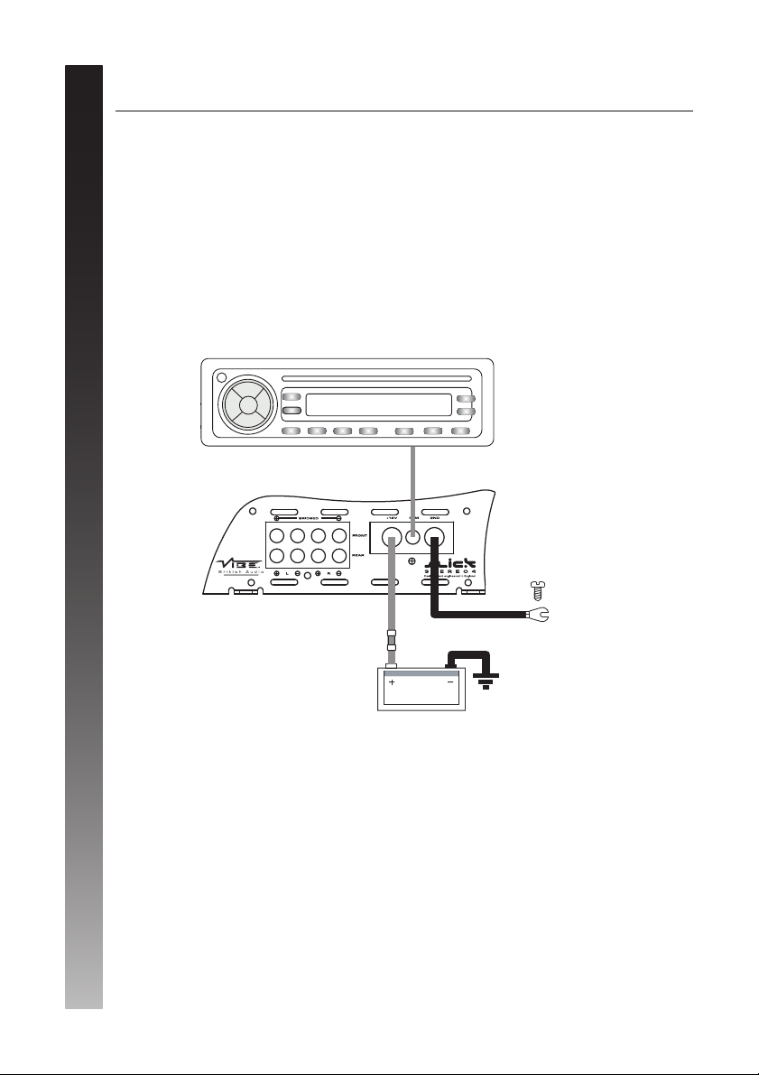
12. Power terminals
Used to connect DC power to the amplifier. See the power connection section for more details.
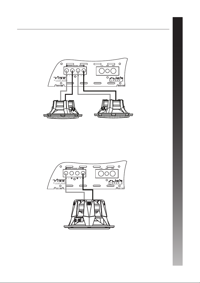
13. Speaker terminals
Used to connect the speaker wires to the amplifier. See the wiring configurations section for more
details.
1 2 4
7
8
9
3 5
10
11
12
13 6