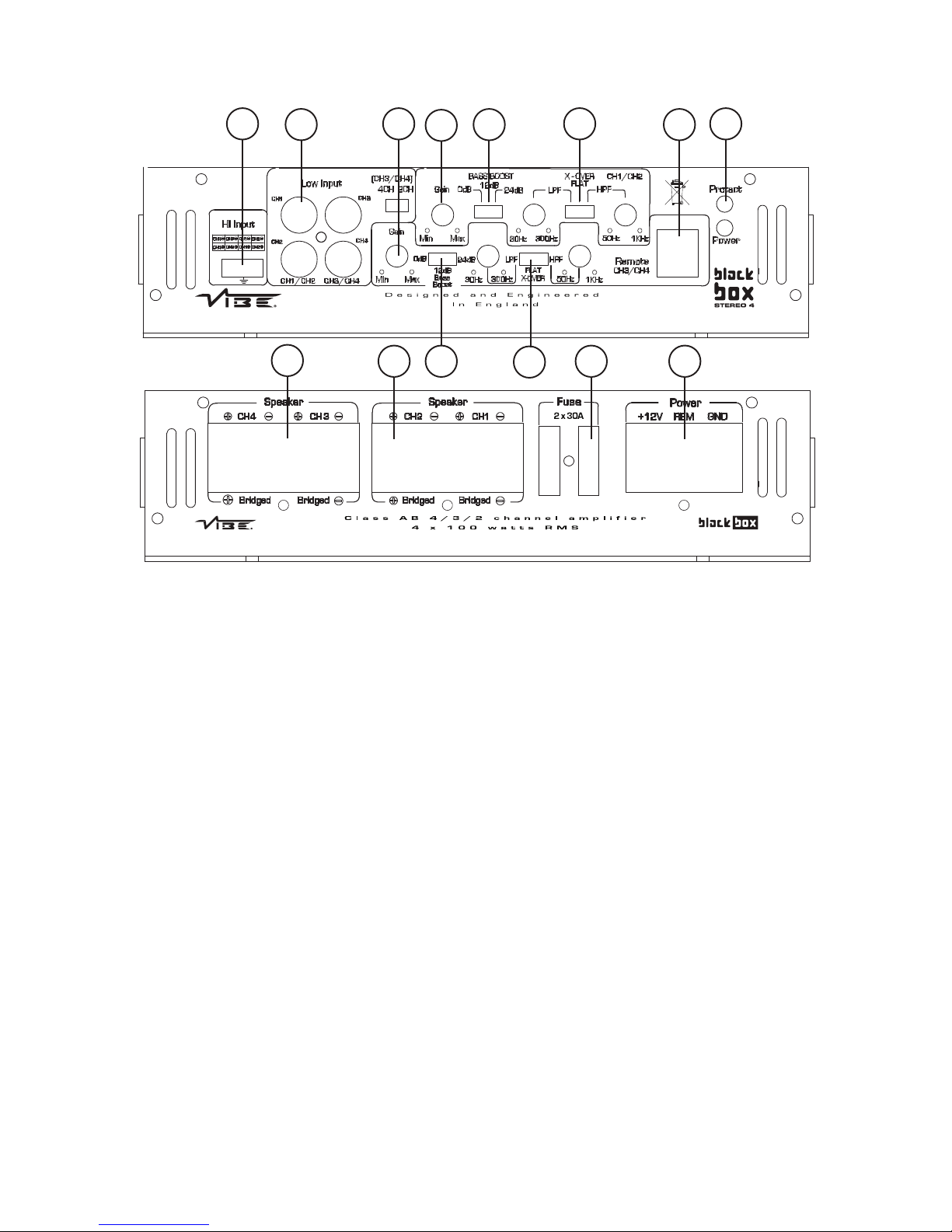
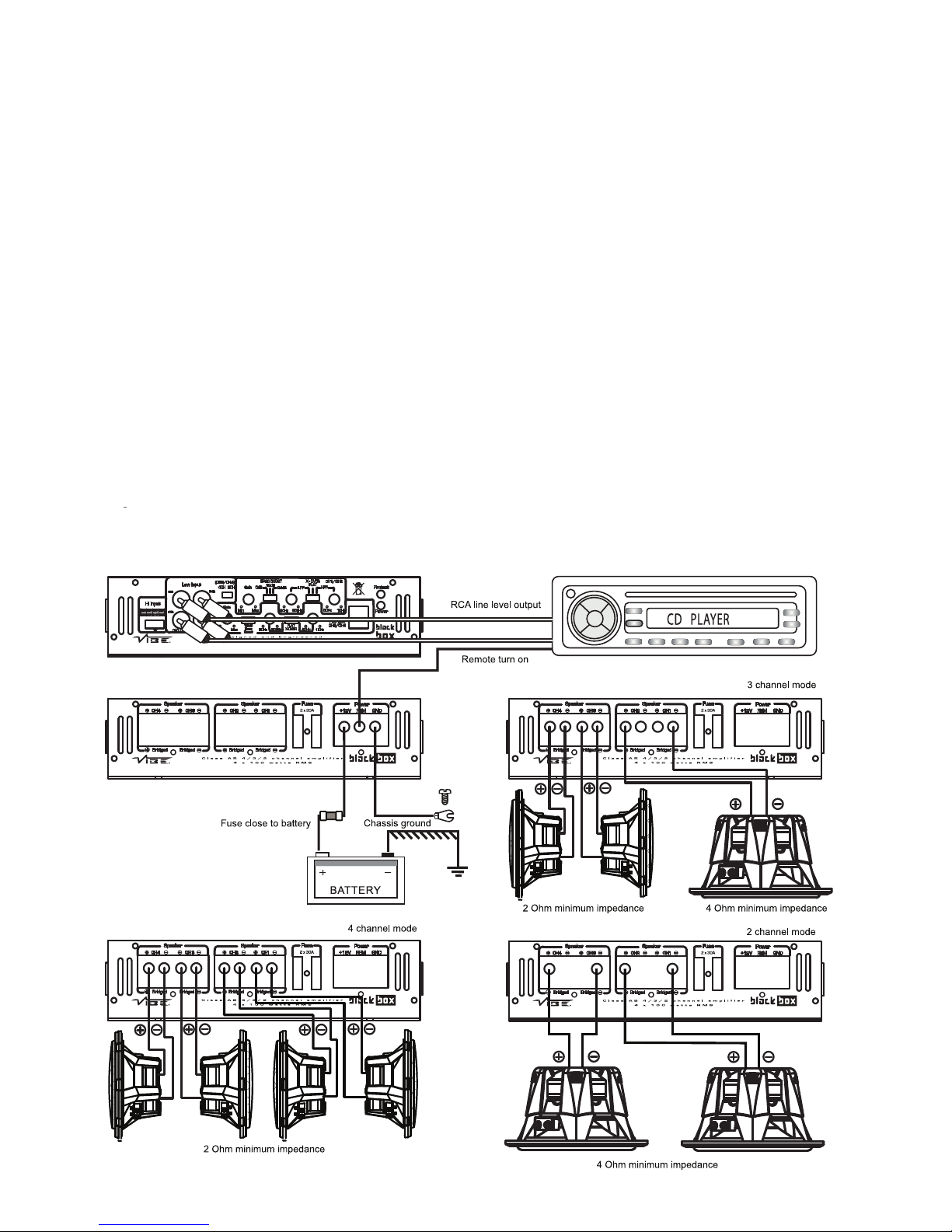
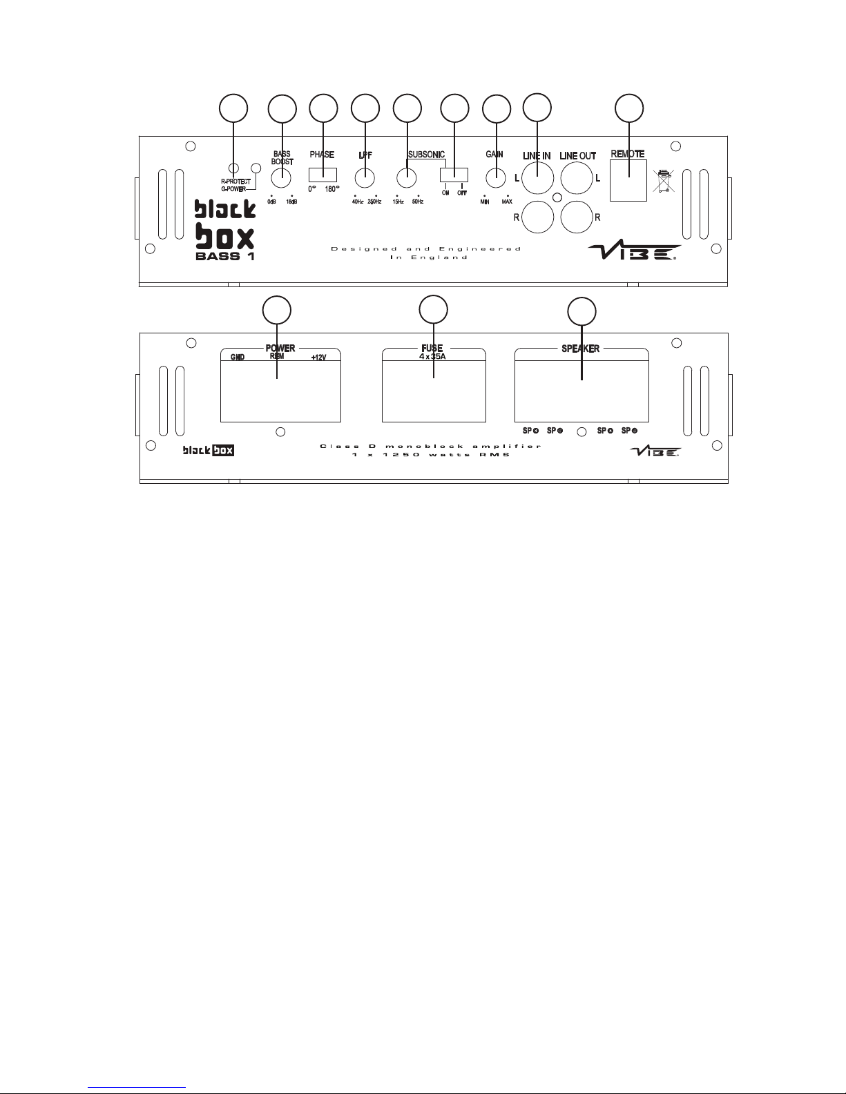
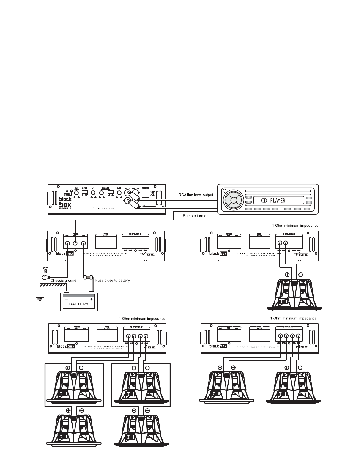
Vibe STEREO 2 User manual

Power Amplifier
Instruction Manual
To ensure maximum performance and safety,
please follow this manual. Please retain the
manual for future reference after installation
STERE 2
STERE 4
BASS 1

FUSE
close to battery
Con ratulations on purchasin your VIBE BlackBox
amplifier Please read this manual in order to fully
understand how to et the best results from your
amplifier.
Please ensure that all advice on how to look after your
amplifier is followed.
Thank you for buyin VIBE, we hope you enjoy listenin to
your product as much as we enjoyed creatin it.
VIBE R&D Division
WNERS MANUAL
Model: BLACKB X STERE 2 / STERE 4 / BASS 1
Mounting Guidelines
Your VIBE amplifier is desi ned with a swift installation routine in mind. Please mount the amplifier in a dry location on a solid
surface. NEVER mount the amplifier upside down, this will cause the amplifier to over heat and will eventually dama e the
amplifier. Before fixin the amplifier in place please ensure that there is sufficient air flow around the exterior of the casin ,
at least two inches is sufficient.

Connections
Ground Cable
●The round cable needs to carry the same current as the power cable. At least an 8 au e cable should be used.
●The amplifier round should be connected directly to the chassis of the vehicle, to bare metal.
●The cable len th should be kept to an absolute minimum.
●It is not recommended that you connect the round cable to the vehicles seatbelts anchor point.
Remote Turn n
●A minimum of 18 au e cable should be used for this connection.
●The cable should be run with exactly the same care and attention as the power cable and taken back to the source
(headunit) and joined to the remote cable provided.
●If the source (headunit) does not have a remote turn on cable then a 12v supply should be used. This will require a
switch to be fitted inline to enable the amplifier to be turned on and off. Remember that if this switch is left on you will
flatten the car battery.
RCA Cables
●Dependin on the model number of your amplifier and the number of speakers you wish to power you will have to run
either one or two RCA cables from the source to the amplifier.
●Please take extra care when runnin these cables from the source to the amplifier. Ensure that they are placed away
from all items that can enerate any interference, wirin harnesses etc.
●It is recommended that the RCA cables should be run on opposite sides of the car to the previously installed power
cables if possible, to avoid the cable pickin up interferance.
Power Cable
●At least an 8 au e cable should be used for both the power and the round connections to the amplifier.
●The power cable should be taken directly from the battery. Rubber rommets should be used when passin throu h
any bulkheads to prevent the cable from becomin chaffed or cut.
●It is vital that a fuse / circuit breaker (of at least equal value to the one fitted on the amplifier) is placed inline with the
power cable and is no further than ei hteen inches away from the battery.
●Please ensure that the fuse is not fitted until the entire installation procedure is complete.
●The two tables below are to help you decide on what cable is correct for you. The first enables you to select the size of
cable dependin on the len th required. The second will help you convert the cable size from American Wire Gau e to
Metric if you need to.
Len th of Run
Current demand 0 – 4 Ft 4 – 7 Ft 7 – 10 Ft 10 – 13 Ft 13 – 16 Ft 16 – 19 Ft 19 – 22 Ft 22 – 28 Ft
0–20 amps 14 12 12 10 10 888
20–35 amps 12 10 886 664
35–50 amps 10 88 64 444
50–65 amps 886 44 442
65–85 amps 664 42 220
85–105 amps 664 22 220
105–125 amps 444 20 000
125–150 amps 222 00 000
AWG to Metric Conversion Chart
cross sectional area
AWG Number Inch mm mm2
0 0.325 8.25 53.5
1 0.289 7.35 42.4
2 0.258 6.54 33.6
3 0.229 5.83 26.7
4 0.204 5.19 21.1
5 0.182 4.62 16.8
6 0.162 4.11 13.3
7 0.144 3.66 10.5
8 0.128 3.26 8.36
9 0.114 2.91 6.63
10 0.102 2.59 5.2

1
10 11 12
2 3 4 567 8 9
Connections and Controls - BlackBox Stereo 2
1. High Level Input
To be used when no RCA's are available. Use the provided loom to connect to closest speakers. The loom connector will only
fit one way around. Once plu ed in you should connect the wires as below:
2. Low Level Input / utput
Low level input connection to any source (head unit) with a low level output. This is your RCA output from the source
(headunit)
Low level output is a daisy chain RCA connection to allow easy addition of another amplifier.
3. Gain Control
Used to match the input si nal of the source to the amplifier. See the setup section for more details.
4. Bass Boost Switch
To provide up to an extra +24 dB of bass boost at 45 Hz. Use this boost to Increase bass output from the amplifier.
5. Low Pass Crossover Control
The control is used to select the low pass filter frequency. The frequency ran es are from 30 Hz to 300 Hz.
6. Crossover Control Switch
This switch is used to select hi h pass, low pass or full (no crossover) operation for the amplifier speaker outputs.
7. High Pass Crossover Control
The control is used to select the hi h pass filter frequency. The frequency ran es are from 50 Hz to 1KHz.

8. Gain Remote Input Jack
Use to plu in the remote bass controller. (BBR09 optional ) see website for details www.vibeaudio.co.uk
9. Indicator LEDs
When the amplifier is operatin correctly the reen LED will illuminate. When the amplifier is in protection mode the red LED
will illuminate
10. Power Connections
Power connections. See Connections section for details on correct connections.
11. Fuses
Please ensure the followin fuse ratin is used when replacin fuses: 15 amp x 2
12. Speaker Terminal utput
For connection to the speakers. See Application section for wirin examples.
Applications - BlackBox Stereo 2

1
23410
13 13 12
5
6
78
9
11
1. Low Level Input
For connection to any source (head unit) with a low level output. This is your RCA output from the source (headunit). In order
to obtain a four channel output from a two channel input please set the switch to 4 channel and plu the RCA's into channel
3 and channel 4.
2. High Level Input
To be used when no RCA's are available. Use the provided loom to connect to closest speakers. The loom connector will only
fit one way around. Once plu ed in you should connect the wires as below:
Front Speakers
Left Positive - Brown Ri ht Positive - Black
Left Ne ative - Blue Ri ht Ne ative - Green
Rear Speakers
Left Positive - Oran e Ri ht Positive - Yellow
Left Ne ative - Grey Left Ne ative - White
3. Front Gain Control
Used to match the input si nal of the source to the amplifier. See the setup section for more details.
4. Front Crossover Control
The switch is used to select between low pass / hi h pass filter or no filter at all on the front channels. The frequency ran es
on the low pass filter are from 30 Hz to 300 Hz. The frequency ran es on the hi h pass filter are from 50 Hz to 1KHz.
5. Front Bass Boost Switch
To provide up to an extra +24 dB of bass boost at 45 Hz. Use this boost to increase bass output from the amplifier.
6. Rear Gain Control
Used to match the input si nal of the source to the amplifier. See the setup section for more details.
Connections and Controls - BlackBox Stereo 4

7. Rear Bass Boost Switch
To provide up to an extra +24 dB of bass boost at 45 Hz. Use this boost to increase bass output from the amplifier.
8. Rear Crossover Control
The switch is used to select between low pass / hi h pass filter or no filter at all on the rear channels. The frequency
ran es on the low pass filter are from 30 Hz to 300 Hz. The frequency ran es on the hi h pass filter are from 50 Hz to
1KHz.
9. Rear Gain Remote Input Jack
Use to plu in the remote bass controller. (BBR09 optional ) see website for details www.vibeaudio.co.uk
10. Indicator LEDs
When the amplifier is operatin correctly the reen LED will illuminate. When the amplifier is in protection mode the red
LED will illuminate
11. Power Connections
Power connections. See Connections section for details on correct connections.
12. Fuses
Please ensure the followin fuse ratin is used when replacin fuses: 30 amp x 2
13. Speaker Terminal utput
For connection to the speakers. See Application section for wirin examples.
Applications - BlackBox Stereo 4

1
4 5 2
6
3
78
11
12
9
10
1. Low Level Input / utput
Low level input connection to any source (head unit) with a low level output. This is your RCA output from the source
(headunit)
Low level output is a daisy chain RCA connection to allow easy addition of another amplifier.
2. Gain Control
Used to match the input si nal of the source to the amplifier. See the setup section for more details.
3. Low Pass Filter Control
Low pass frequency control. The frequency ran es from 40 Hz to 250 Hz.
4. Phase Control
Can be used to alter the phase of the subwoofer from 0 - 180 de rees.
IE: The speaker output can be In phase or out of phase with the other speakers in the vehicle. For best results flick between
the two settin s to determine the best results.
5. Subsonic Filter Control
This is used to filter out unwanted amplifier output to the subwoofer. Effectively this will filter out all the frequencies up to the
crossover point set with the control. The ran e is from 15 Hz to 50 Hz. Frequencies of 80 Hz and below cause the subwoofer
to work hard, some subwoofers can easily be dama ed when playin very low frequencies. Usin the subsonic filter allows
less distortion, delivers frequencies better suited to the subwoofer prolon in its life.
6. Subsonic Filter Switch
Used to turn the filter on or off.
7. Bass Boost Switch
To provide up to an extra +18 dB of bass boost at 45 Hz. Use this boost to increase bass output from the amplifier.
Connections and Controls - BlackBox BASS 1

8. Bass Remote Input Jack
Use to plu in the remote bass controller.
9. Indicator LEDs
When the amplifier is operatin correctly the LED will show as blue. When the amplifier is in protection mode the LED will
show as red.
10.Fuses
Please ensure the followin fuse ratin is used when replacin fuses:
35 amp x 4
11. Speaker Terminal utput
For connection to the speakers. See Application section for wirin examples.
12. Power Connections
Power connections. See Connections section for details on correct connections.
Applications - BlackBox Stereo 4

Set Up Section
To correctly set the ain control of the amplifier to match that of the source (headunit) use the followin setup routine:
Turn the ain control to minimum on the amplifier.
Ensure the bass boost is set to 0 dB.
On the headunit set all crossovers ( if applicable) to flat and both bass and treble to zero.
Turn up the source (headunit) to approx 3/4 volume.
Very slowly turn up the ain on the amplifier until distortion can be heard in any of the speakers or until the volume reaches
an uncomfortable listenin level when this is reached turn down the ain control sli htly.
The gain control is now set.
The settin of the crossover will depend on what kind of speaker you are installin .
For a subwoofer it is recommended that the crossover is set to Low Pass and the frequency is set to match that of the
speakers specifications, or your preferred frequency - this is usally about 60 - 120
For a pair of full ran e speakers it is recommended that the crossover is set to Flat. The two frequency controls will then
have no effect on the amplifiers output and the speaker will receive a full ran e si nal. However, usin the hi h pass
crossovers will allow more control of your speakers. By removin the bass (low frequencies) the speakers can perform at
hi her volumes with less distortion.
Note: The smaller the speaker, the less bass it can handle. Adjust the crossover to et the most and best sound from your
speakers. The easiest was to do this is by limitin the amount of bass you feed them.
For a pair of speakers with a passive crossover it is recommended that the crossover is set to Hi h Pass and the frequency
is set to match that of the speakers specifications. - This is usually about 40 - 120Hz
Note:
By usin the crossovers correctly you will not only len then the life of your speakers but you will also et better performance
from them. To optimise your setup seek the advise of a professional installation en ineer or visit your local VIBE audio dealer.

Troubleshooting
●Before removin the amplifier, refer to the list below and follow the su ested procedures.
●Always test the speakers and confirm that they are wired correctly first.
●If in any doubt et help from a qualified auto electrician.
Amplifier Will Not Power Up
✓Check for ood round connections. Ensure Ground cable is connected directly to bare metal and not a painted
surface.
✓Usin a multimeter check that remote terminal has at least 7V DC.
✓Usin a multimeter check that there is battery volta e of at least 10.5v DC on the positive terminal.
✓Check all fuses.
✓Check that the protection li ht is not illuminated. If it is lit, shut off the amplifier by disconnectin for thirty seconds and
then turnin it back on.
Protection LED Illuminates When Amplifier Is Powered Up
✓Check for shorts on all speakers wires. (IE no speaker wires should be joined to ether and no speaker wires should be
touchin the cars chassis)
●The amplifier is desi ned to shut down automatically when the units temperature oes above 80 de rees. If the
amplifier feels very hot then this may be the reason for the amplifier not startin .
●Remove the speaker wires and reset the amplifier. If the Protection LED still comes on then the amplifier is faulty. This
dama e may have been caused by either failure to follow these setup uidelines or abuse.
Amplifier Gets Very Hot
✓Check the minimum speaker impedance for the amplifier is correct.
✓Check for shorts on all speakers wires. (ie no speaker wires should be joined to ether and no speaker wires should be
touchin the cars chassis)
✓Check that there is ood airflow around the amplifier. In some applications an external fan may be required.
Blown Fuse(s)
✓Check both positive supply and round for shorts.
✓Check that the positive wire is connected to the positive terminal on the amplifier.
✓Check that the ne ative wire is connected to the round terminal on the amplifier.
✓Ensure that the correct rated fuse is fitted:
VIBE BlackBox Stereo 2 –15 amp x 2,
VIBE BlackBox Stereo 4 –30 amp x 2,
VIBE BlackBox Bass 1 –35 amp x 4,
Distorted Sound
✓Check the ain control is not set at too hi h If the speakers sound distorted turn down the ain until the
sound is clear.
✓Check that all crossover frequencies are correct. See Setup section for more details.
✓Check for shorts on all speaker wires.
✓Check all speakers are wired correctly. With the correct polarity bein observed on each connection.

Specification BlackBox stereo 2
RMS Power @ 13.8v DC
Power @ 4 Ohms stereo 2 x 100 WRMS
Power @ 2 Ohms stereo 2 x 125 WRMS
Power @ 4 Ohms bridged 1 x 250 WRMS
Minimum speaker impendence 2 Ohm stereo / 4 Ohm bridged
HD Distortion 0.1%
IMD Distortion 0.1%
Frequency Response 7Hz - 38 KHz
Input Sensitivity 250 mV - 5V
Input Impendence 15K
Signal to Noise Ratio 96 dB
Channel Separation -61 dB
Crossover Network
Low pass filter 30 Hz – 300 Hz
Bass Boost 0 dB - +24 Db
High pass filter 50 Hz – 1KHz
Fuse rating 15A x 2
Size length x width x height 348mm x 224mm x 57 mm
BlackBox stereo 4
4 x 100 WRMS
4 x 125 WRMS
2 x 250 WRMS
2 Ohm stereo / 4 Ohm bridged
0.1%
0.1%
5Hz - 43 KHz
250 mV - 5V
15K
88 dB
-57 dB
30 Hz – 300 Hz
0 dB - +24 Db
50 Hz – 1KHz
30A x 2
448mm x 224mm x 57 mm
Specification BlackBox bass 1
RMS power @ 13.8 vDC
Power @ 4 ohms 1 x 650 WRMS
Power @ 2 Ohms 1 x 1000 WRMS
Power @ 1 Ohm 1 x 1250 WRMS
Minimum speaker impedance 1 ohm
HD Distortion 0.8 %
IMD Distortion 0.8 %
Input Sensitivity 250 mv - 5V
Input Impedance 15 K
Signal to Noise Ratio 95 dB
Crossover Network
Low Pass Filter 40 Hz - 250 Hz
Bass Boost 0 dB -+18 dB
Subsonic Filter 15 Hz - 50 Hz
Fuse Rating 35 amp x 4
Size length x width x height 478 mm x 224mm x 57mm
BlackBox stereo amplifiers
BlackBox bass amplifier


Copyright
All content included in this manual such as text, graphics, logos, icons, images and data, are the property of VIBE Technologies Limited (herein referred to as "VIBE", "us" or "we") and its affiliate or
their content and technology providers, and are protected by United Kingdom and International copyright laws. All rights reserved.2008
All stylised representations of product names, or the abbreviations of product names, as logos are all trademarks of VIBE. Graphics and logos are trademarks or trade dress of VIBE Technologies
Ltd or its subsidiaries.
VIBE's trademarks and trade dress may not be used in connection with any product or service that is not VIBE's, in any manner that is likely to cause confusion among customers or in any manner
that disparages or discredits VIBE. All other trademarks not owned by VIBE or its subsidiaries that appear in this manual are the property of their respective owners, who may or may not be affiliated
with, connected to, or sponsored by VIBE or its subsidiaries.
TO THE FULLEST EXTENT PERMITTED AT LA , VIBE IS PROVIDING THIS MANUAL AND ITS CONTENT ON AN "AS IS" BASIS AND MAKES NO (AND EXPRESSLY DISCLAIMS ALL)
REPRESENTATIONS OR ARRANTIES OF ANY KIND, EXPRESS OR IMPLIED, ITH RESPECT TO THIS MANUAL OR THE INFORMATION, CONTENT, MATERIALS OR PRODUCTS
INCLUDED IN THIS MANUAL INCLUDING, ITHOUT LIMITATION, ARRANTIES OF MERCHANTABILITY AND FITNESS FOR A PARTICULAR PURPOSE.
IN ADDITION, VIBE DOES NOT REPRESENT OR ARRANT THAT THE INFORMATION CONTAINED IN THIS MANUAL IS COMPLETE OR CURRENT, AND THAT ALL SPECIFICATIONS AND
INFORMATION CONTAINED ITHIN THIS MANUAL ARE SUBJECT TO CHANGE ITHOUT NOTICE.
VIBE RECOMMEND CAUTION HEN LISTENING TO MUSIC REPRODUCED THROUGH VIBE EQUIPMENT. VIBE EQUIPMENT IS CAPABLE OF PRODUCING SOUND AND SOUND
PRESSURE LEVELS THAT CAN PERMANENTLY DAMAGE HEARING OF YOU AND THAT OF OTHERS. FOR SAFE AND ENJOYABLE LISTENING, THE SOUND SHOULD BE CLEAR
ITHOUT DISTORTION AT A COMFORTABLE VOLUME.
BY USING ANY VIBE EQUIPMENT, YOU AGREE TO TAKE FULL RESPONSIBILITY FOR YOUR O N SAFETY AND THE SAFETY OF OTHERS HEN LISTENING TO MUSIC AT HIGH
VOLUMES THROUGH EQUIPMENT YOU HAVE PURCHASED. USE OF ANY VIBE EQUIPMENT CONSTITUTES AGREEMENT TO THIS DISCLAIMER.
Except as specifically stated in this manual, to the fullest extent permitted at law, neither VIBE nor any of its affiliates, directors, employees or other representatives will be liable for damages arising
out of or in connection with the use of this manual or the information, content, materials or products included.
This is a comprehensive limitation of liability that applies to all damages of any kind, including (without limitation) compensatory, direct, indirect or consequential damages, loss of data, income or
profit, loss of or damage to property and claims of third parties. For the avoidance of doubt, VIBE does not limit its liability for death or personal injury to the extent only that it arises as a result of
negligence of VIBE, its affiliates, directors, employees or other representatives.
Limited Warranty
All VIBE products carry a full twelve months warranty, valid from the date of the ori inal receipt / proof of purchase. In
order to validate this warranty, the warranty card should be returned to VIBE within seven days of the ori inal purchase
date. The ori inal receipt and packa in should also be retained for this twelve month period.
If at any sta e durin the warranty period you have a problem with the product then it should be returned to the point of
purchase, with proof of purchase in its ori inal packa in , complete with no items missin .
If the store is unable to fix the product it may have to be returned to VIBE this process takes around 7 workin days.
A full description of VIBE's warranty information can be found on our website:
www.vibeaudio.co.uk/warranty
A written version can also be obtained from
VIBE warranty Dept, PO BOX 11000, B75 7WG
Technical enquires
call 09067031420
call cost 50p per minute Call costs correct at date of publication (02/02/08) Hours of business 9.00am - 5.30pm all calls are recorded for trainin
purposes MIDBASS Distribution PO Box 11000,B75 7WG
In order to protect your purchase and aid your
arrantee please fill in the follo ing form and
keep it safe for your future reference:
Model Number:
Serial Number:
Purchased From:
Date of Purchase:
KEEP IT SAFE
Staple your receipt here:

FLATBASS™ 13 SPK Bass speaker cable
There are many powerful bass amplifiers on today’s market – the ever increasin power is puttin hu e strains on speaker wire
– VIBE present a new breed of speaker cable specially developed for BASS applications – the VIBE FLATBASS speaker cable
offers SolidCores™ that can handle and sustain considerably more power than conventional speaker cable.
Model: FlatBass 13 SPK – 13 au e SolidCore™ flat BASS speaker cable
VIBE 140 amp circuit breaker
Bi systems require bi protection – The VIBE circuit breaker is rated at a massive 140 amps and offers critical protection to
your system – if the system over powers or short circuits the breaker will cut in and save your equipment. No need to replace
expensive fuses, system is reset via a simple switch – also offers safe and instant system shutdown.
Model: CB140 – 140 amp circuit breaker
FLAT Y 2M / FLAT Y 2F RCA Y leads
Our professional quality full ran e OFC Y-interconnect uarantees a pure and stron si nal. With a flat
desi n and ferrite loaded old plated plu s interference is reatly reduced. The FLAT-Y Interconnect is
available in 1 male – 2 female FLAT Y 2F and 2 male – 1 female FLAT Y 2M confi urations.
Model: FLAT Y 2f – 1 pair RCA Y lead 1male to 2 female
Model: FLAT Y 2m – 1 pair RCA Y lead 2male to 1female
VIBE SD4/5 subwoofer defender rill
The new VIBE subwoofer defender not only provides protection for your sub but also adds style with its metallic
bad e and black rubberised steel construction allow it to inte rate perfectly with the VIBE EVO enclosures
Model: SD4 – sub rill fits both 10” and 12” subwoofers
Model: SD5 – sub rill fits 15” subwoofers
VIBE BC10 level controller
The VIBE BC10 ain level controller is a perfect addition to any subwoofer system, the BC10 allows the level of the amplifier to be
controlled from the driver’s seat ivin the user easy adjustment of ain level. Particularly useful for adjustin the ain level for
amplifiers controllin subwoofers. The BC10 controller is RCA input and output makin it compatible with any system allowin ain
level adjustment of any amplifier it is connected to. It can also be used with full ran e amplifiers.
Model: BC10 – RCA Gain level control
Slick level remote
A new addition to the Slick ran e of amplifiers is the Slick level control which allows level adjustment of the amplifier from the front of
the car - Simply plu the supplied cable into the Slick remote level port on the end panel of the amplifier and remote ain control is
yours, it is that easy.
Model: SLR1 – optional remote for use with all Slick amplifiers
VIBE PortPlu ™
The VIBE PortPlu allows easy tunin of the VIBE CBR bass enclosures. The PortPlu ™ is used to ti htly
seal the VIBE TurboPort™ in the enclosure to either create a sealed enclosure for better transient
response or in the case of a multi ported enclosure re-tune the enclosure usin only 1 PortPlu ™
Model: PP25 – PortPlu ™ for 2.5” TurboPort™
Model: PP30 - PortPlu ™ for 3” TurboPort™
VIBE official Merchandise
MPS – VIBE polo shirt with embroidered VIBE lo o on front and rear
MTS – VIBE T-shirt with small VIBE printed lo o on front.
MCD – VIBE CD, containin exclusive VIBE bass tracks as featured on the Bass Tunnel and VIBE Dredd.
MCC – VIBE CD case, metallic silver CD case with VIBE lo o.
VFL – VIBE fleece with embroidered lo o on the front and lar e on back.
VTD – VIBE tax disc holder, stylish silver tax disc holder featurin VIBE lo o.
VIBE GB41 banana plu
The VIBE GB41 banana plu s are the easy and convenient way to quickly remove your bass enclosure without
havin to constantly re-thread your speaker cable into the box terminal, simply attach the speaker cable to the
VIBE GB41 banana plu and you have a reliable quick release solution. Desi ned for optimum use with the TP-2
and QP-4 terminal, our professional old plated 4mm banana plu s are polarity marked and feature rubber
shrouds.
Model: GB41 – Gold Banana plu
VIBE FD4 fused distribution block
The VIBE FD4 fused distribution block is a professional AGU fused distribution block which ives easy
connection for up to 4 amplifiers. The VIBE FD4 has 1 x 4AWG input and 4 x 8AWG outputs each
individually fused up to a maximum of 80 amps (AGU fuses available separately)
Model: FD4 – 4 way AGU fused distribution block, 1 x 4 au e input 4 x 8 au e outputs
VIBE RT4 / RT8 crimp on rin terminal
The professional ran e of VIBE RT old plated rin terminals for connectin power cable to the vehicle
battery. Packed in pairs and include red and black rubber over boots with are easy crimp desi n.
Model: RT8 – 1 pair of 8 au e crimp on rin terminals with PVC overboots
Model: RT4 – 1 pair of 4 au e crimp on rin terminals with PVC overboots
VIBE CT0 / CT4 compression fit rin terminal
The VIBE CT ran e of old plated rin terminals are professional compression fit desi ned for maximum
conductivity when connectin power cable to the vehicle battery. The VIBE RT compression fit terminals are
the best way to connect heavy au e power cable to the vehicles battery.
Model: CT0 – 0 au e compression fit rin terminal
Model: CT4 – 4 au e compression fit rin terminal
VIBE DB6 non fused distribution block
The VIBE DB6 non fused distribution block is a professional non fused distribution block which ives easy
connection for up to 5 amplifiers. The VIBE DB6 has 2 x 4AWG input and 4 x 8AWG outputs which can be
used for power distribution or round distribution ivin a common roundin point for all system
components eliminatin the risk of round loop interference.
Model: DB6 non fused distribution block
VIBE AGU30, AGU60, AGU80 fuses
The VIBE AGU fuse series are the perfect companion to the VIBE FD4 fused distribution block and the Active
and stereo system wirin kits.
Model: AGU30 – 1 pair 30 amp AGU fuses to fit all AGU fuse holders
Model: AGU60 – 1 pair 60 amp AGU fuses to fit all AGU fuse holders
Model: AGU80 – 1 pair 80 AGU fuses to fit all AGU fuse holders
For more product info see www.vibeaudio.co.uk
All Accessories are available direct, for next day delivery call 0870 765 8423 or vist www.vibeauduo.co.uk/shop (UK ONLY)

The CriticalLink™ range of FLAT series cabling from VIBE
The VIBE CriticalLink ran e of cablin has been developed to achieve the critical link between source (headunit), amplifier and speakers –
VIBE audio equipment is hi h quality, usin anythin less than the VIBE CriticalLink™ ran e of cables will severely compromise your
equipment and will not allow it to perform to its maximum potential.
NOTE: Your audio equipment will only ever be as ood as the cables you use to connect it. The link between your audio equipment is critical
for a bi er cleaner sound.
VIBE cabling and interconnects can enhance your system power and sound quality by more
than 20% over other brand cable.
FLATSTEREO™ Hi h Definition full ran e Interconnect
The VIBE FLATSTEREO RCA is an OFC hi h definition full ran e interconnect – deliverin the fullest si nal possible from source to
amplifier - the cable make up has been developed to run flat with left and ri ht cables runnin parallel both with individual screenin but
sharin an outer FLAT jacket easin installations.
Available in:
Model: FlatStereo RCA 1m – 1 metre full ran e interconnect
Model: FlatStereo RCA 5m - 5 metre full ran e interconnect
FLATBASS™ – SolidCore™ Bass interconnect
The VIBE FLATBASS™ interconnect has been specifically developed for use in BASS SYSTEMS - the cable make up has a unique super
FLAT™ desi n easin installation - Its trick in redient is oversized SolidCore™ OFC si nal wires - allowin a heavier volta e to be passed
down the cable. This is the central wire that caries the main si nal from source to amplifier.
Available in:
Model: FlatBass RCA 1m – 1 metre BASS interconnect
Model: FlatBass RCA 5m - 5 metre BASS interconnect
FLATFLEX™ Hi h Definition speaker cable
The delivery of power and si nal to the speaker is the final CriticalLink™ in any audio system – VIBES FlatFlex OFC hi h definition
speaker cable is produced from super fine OFC copper strands collectively pickin up all the detail in your music – the multi strands
are ali ned in a row makin the cable super FLAT™ which can be run invisibly under carpets.
Available in:
Model: FlatFlex 16 SPK – 16 au e Hi h definition flat flexible speaker cable
Model: FlatFlex 12 SPK – 12 au e Hi h definition flat flexible speaker cable
FLATLINES™ Power and Ground Cable
VIBE FlatLines™ power cable has been developed to maximises volta e transfer from battery to amplifier - The cable has 2 main lines
runnin side by side which are made up of fine copper strands - This desi n makes the cable flat allowin us to make very slim heavy duty
power cable which is hi hly flexible easin installation.
Available in: system kits, by the roll or by the metre
Model: FLATLINES 8 PWR – 8 au e red power cable Model: FLATLINES 8 GND – 8 au e black power cable
Model: FLATLINES 4 PWR – 4 au e red power cable Model: FLATLINES 4 PWR – 4 au e red power cable
Model: FLATLINES 0 PWR – 0 au e red power cable Model: FLATLINES 0 GND – 0 au e black power cable
BASS SYSTEM KIT
The VIBE 3000watt BASS KIT is specifically desi ned to ain maximum output from hi h power Bass systems. Featurin the best BASS specific
cables from the VIBE CriticalLink™ Ran e.
Contents of this Kit:
FLATLINES™ 4AWG PWR Power and Ground cable
FLATBASS™ RCA SolidCore™ Interconnect
FLATBASS™ 13 SPK Bass speaker cable
FLATLINES ™ remote 18
VIBE 140 amp circuit breaker
All cable is terminated with crimped terminal rin s in place and accessory fittin kit
COMPATIBILITY
This kit is compatible with the majority of amplifiers on the market – VIBE recommends this kit for all VIBE BASS monoblock amplifiers new, current
and old models.
Model: Bass Kit – Bass specific amplifier wirin kit
STEREO SYSTEM KIT
The VIBE 1500 watt STEREO KIT is specifically desi ned to ain maximum output from hi h power full ran e systems. Combinin the best full
ran e cables from the VIBE CriticalLink ™ ran e.
Contents of this Kit:
FLATLINES™ 8AWG PWR Power and Ground cable
VIBE FLATSTEREO™ RCA - OFC hi h definition full ran e interconnect
FLATLINES ™ remote 18
FLATSTEREO™ speaker cable
AGU Fuse Holder
All cable is terminated with crimped terminal rin s in place and accessory fittin kit
COMPATIBILITY
This kit is compatible with the majority of amplifiers on the market – VIBE recommends this kit for all VIBE full ran e STEREO amplifiers new,
current and old models. FLATLINES™ 8 PWR Power
Model: Stereo Kit – full ran e stereo amplifier wirin kit
ACTIVE SYSTEM KIT
The VIBE 1500watt ACTIVE BASS KIT is specifically desi ned to ain maximum output from hi h power Active Bass systems (Bass Boxes).
Featurin BASS specific components from the VIBE CriticalLink™ ran e.
Contents of this Kit:
FLATLINES™ 8AWG PWR Power and Ground cable
FLATBASS™ RCA SolidCore™ Interconnect
FLATLINES ™ remote 18
AGU Fuse Holder
FastPlu ™
COMPATIBILITY
This kit is compatible with the majority of amplifiers on the market – VIBE recommends this kit for all VIBE active bass enclosures new, current and
old models.
Model: Active Kit – Bass specific active enclosure wirin kit
The VIBE FastPlu ™ (pat. pendin ), is a product lon overdue. Desi ned and developed by VIBE En ineers the plu
offers safe, fast removal of your active bass enclosure (bass box) or amplifier. You may wish to remove your
system for security reasons, or for the full use of your boot space, whatever the reason the VIBE FastPlu makes
it easy and safe.
The plu is a heavy duty connector that connects positive, ne ative and remote wires. It is made up of 2 parts –
one end to connect to your equipment and the other to your power source – made from hi h quality ABS plastic
the device is tou h and hard wearin . Model: FASTPLUG
The Deltabox line driver is the ideal solution for those lookin to install multiple amplifiers from a sin le RCA preout. Most people use
RCA “Y” splitters for this task unaware of the si nal de radation caused. The Deltabox not only divides the si nal but also isolates and
boosts the si nal up to a maximum of 9 volts independently for each of the 3 output channels ivin much cleaner sound and
excellent si nal to noise ratio. For SPL competition the Deltabox is an essential tool as each of the outputs can be split 4 times ivin
control of 12 amplifiers from a sin le ain enablin precise adjustment of the system without havin to reset every amplifier
individually. Additionally if your headunit has a weak preout or you wish to run multiple amps but only have one output the Deltabox™
is your ideal solution. Model: DELTABOX
The VIBE 1.5 farad power capacitor is a must for any hi h performance audio system. VIBE’s 1.5 farad power capacitor
brid es the ap between the vehicles battery and the amplifiers ensurin rapid smooth current flow resultin in louder
ti hter bass and clean crisp midran e and treble. The built in di ital volta e display constantly and accurately displays the
systems DC volta e. An all new VIBE power distribution block is built into the top of the capacitor to allow easy wirin into
the system and also will allow 3 amplifiers to be wired directly to the capacitor for maximum current flow to the amplifiers.
Model: PC15
For more product info see www.vibeaudio.co.uk
All Accessories are available direct, for next day delivery call 0870 765 8423 or vist www.vibeauduo.co.uk/shop (UK ONLY)
This manual suits for next models
5
Table of contents
Other Vibe Amplifier manuals

Vibe
Vibe Slick Stereo 2 User manual

Vibe
Vibe SLICK a0 User manual

Vibe
Vibe POWERBOX 60.2 User manual

Vibe
Vibe BASS4-V1 User manual

Vibe
Vibe STEREO2-V1 User manual

Vibe
Vibe Monobox III User manual

Vibe
Vibe POWERBOX 500.1 User manual

Vibe
Vibe Slick a7 User manual

Vibe
Vibe SLICK C10A User manual

Vibe
Vibe Powerbox Micro POWERBOX 400.1M User manual