VIBROBIT 100 User manual

26.51.66.133
EQUIPMENT ‘VIBROBIT 100’
DEVICE ADJUSTERS PN11
Operation and Maintenan e Manual
VSPA.421412.174 RE
Rostov-on-Don
2019
SCIENTIFIC-PRODUCTION
ENTERPRISE VIBROBIT LLC

SPE VIBROBIT LLC
Address: 344092, Russia, Rostov-On-Don, Kapustina St, , building A (PO Box №53)
Tel./Fax: +7 63 21 -24-75, +7 63 21 -24-7
E-mail: [email protected]
http: // www.vibrobit.ru
The Operations and Maintenance Manual (OMM) is designed to guide users (workmen) the
purpose and operation of the instrument repairman PN11.
The user must know the rules of operation of electrical appliances, have experience with
technology of radio, as well as to know the purpose and work equipment "VIBROBIT 100".
03.12.19 (Version 5)
2

1 Des ription and Operation
1.1 Designated purpose of the devi e adjusters PN11
The device adjusters PN11 is intended for checking the technical condition of the equipment
"Vibrobit 100" during installation, adjustment, installation and maintenance.
The device is used to test and calibrate:
-sensors with transducers;
-sensors with comparators;
-control boards;
The instrument is adjusted and checked as separate units of equipment and measurement
channels.
1.2 Devi e omponents
- device adjusters PN11 1 pcs;
- signal cable 1 pcs;
- power cord 1 pcs;
- rechargeable Battery Ni-MH (AA) 4 pcs
1.3 Devi e spe ifi ations and hara teristi s
The main technical features of the device of the adjuster of PN11 are specified in Table 1.
Table 1 - Main technical characteristics of the PN11 commissioner
Parameter Norm
The output voltage of positive polarity, V 24 0,5
The load current is not less, А 0,15
Measuring ranges DC (from and to inclusion), mA 0 - 5
0 - 20
Measuring ranges DC voltage (from and to inclusion), V 0 - 20
0 - 40
The range of the battery voltage measurement (from and to inclusion), V 0 - 10
Measuring ranges RMS vibration (from and to inclusion), mm / sec 0 - 15
0 - 30
The maximum error of measurement,%, not more 1.5
Range of supply voltage alternating current frequency of 50 (60) Hz, V 150 - 250
Maximum power consumption, watt, not more 6,0
Overall dimensions, mm 196х100х40
Weight, kg, no more 0,3
3

1.3.1 The device must retain its characteristics
– at a temperature from +5 to + 50 0С;
– at a temperature of 35 0С at a relative humidity of 0 % without condensation.
1.3.2 Warm-up time (Warm) must not exceed 1 minute.
1.3.3 The insulation resistance in the circuit ~ 220 V should be less than:
– 40 megohms – in normal conditions of operation;
– 2 megohms – at a temperature plus 35 0C and the relative humidity of 0 %.
Insulation of electrical circuits with a voltage of 220 V to withstand test voltage of 0.9 kV for one
minute.
1.3.4 Voltage industrial interference, μVdB, not more:
– at frequencies from 0,15 to 0,5 MHz 0;
– at frequencies from 0,5 to 2,5 MHz 74;
– at frequencies from 2,5 to 30 MHz 60.
1.3.5 The average service life of the device - 5 years. Lifetime does not apply to batteries, for which
lifetime depends on the number of cycles "charge-discharge".
1.4 Design and operation of the devi e
1.4.1 Structurally the device is executed in a portable version in the standard package of high impact
BOS 00 phenol-formaldehyde plastics production company «BOPLA» (Germany).
1.4.2 Controls and indicators are located on the top front panel in accordance with Annex A.
4

Appointments controls and information are listed in Table 2.
Table 2 - Controls and Information
Controls and Information Purpose
Button «POWER ON» switching on device.
Button «POWER OFF» switching off device
Fuse «2,0 А» Fuse primary circuit (VP-1-1 2А)
(CAUTION! 220V);
Fork block «220 V» Connecting the power cord;
(CAUTION! 220V);
Fork block «CIRCUIT» Connecting the power cord
Light indicator
«POWER ON» Display of the operating mode of the device
Light indicator «220 VАС ON» Display of voltage AC 220 V
Light indicator «BATTAREY
CHARGE»
Display mode battery charge
The buttons and lights select the measured parameter
(MEASURING PARAMETR)
Button «V DC» Enabling measure DC voltage
Light indicator «V DC» Displays measurement mode DC voltage
Button «I DC» Enabling DC measurement.
Light indicator «I DC» Displays measurement mode DC.
Button «RMS» Enabling measuring vibration.
Light indicator «RMS» Display mode measuring vibration.
Button «V BAT» Enabling measure DC voltage on batteries.
Light indicator «V BAT»Displays measurement mode DC voltage at the
batteries.
The buttons and lights measuring range selection
(RANGE)
Button «1…5»
Activating the measurement::
DC in the range of 0 to 5 mA,
DC voltage in the range of 0 to 20 V
RMS vibration in the range of 0 to 15 mm / sec
5

Continuation of Table 2
Controls and Information Purpose
Light indicator «1…5»
Displays measurement mode:
DC in the range of 0 to 5 mA,
DC voltage in the range of 0 to 20 V
RMS vibration in the range of 0 to 15 mm / sec
Button «4…20»
Activating the measurement:
DC in the range of 0 to 20 mA,
DC voltage in the range of 0 to 40 V
RMS vibration in the range of 0 to 30 mm / sec
Light indicator «4…20»
Displays measurement mode:
DC in the range of 0 to 20 mA,
DC voltage in the range of 0 to 40 V
RMS vibration in the range of 0 to 30 mm / sec
The buttons and lights measuring channel selection
(CHANNEL)
Button «CH1» Enabling DC measurement values and vibration velocity
in the channel 1.
Light indicator «CH1» Display mode DC measurement values and vibration
velocity in the channel 1.
Button «CH2» Enabling DC measurement values and vibration velocity
in the channel 2.
Light indicator «CH2» Display mode DC measurement values and vibration
velocity in the channel 2.
6

2 Intended use
2.1 Safeguard
– When working on the device voltage circuit elements are life-threatening. It is strictly
forbidden to break the sealing device and make measurements of the electrical parameters within the
device.
– Disconnect the power cord from the unit carried out only after disconnecting the power cord
from the mains.
– Check and replace the fuse only after disconnect the device from the network.
– To prevent the exploitation of persons having a third and higher group on electrical safety.
2.2 Operational pro edure
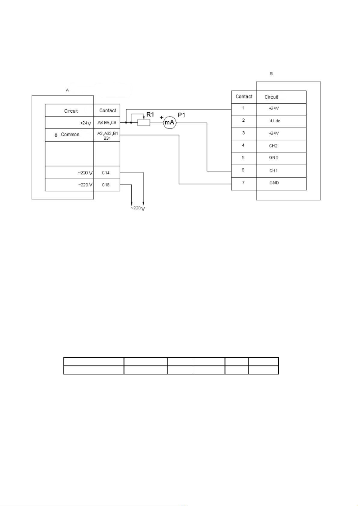
Connect the cable signal to block the fork «CURCUIT».
Attention! It is stri tly prohibited to short- ir uit onne tor "+ 24 V» on the plug «CH1» and
«CH2». This an lead to overload and failure of the urrent sensor.
Connect the unit under test, observing the name chains (shown on cable plug). When running on the
network to connect the power cord to the device itself shnur- to AC power. This indicator light "220 VAC
ON», LED «POWER ON», the decimal point in the third discharge, the indicator and the indicator light
«BATTAREY CHARGE», if the battery level is below normal. Intermittent flashing indicator light
«BATTAREY CHARGE» indicates the absence of batteries in the battery compartment or poor contact
with the slip slats.
When running on batteries the device is activated by pressing and holding the button «POWER ON»
before the decimal point in the third discharge indicator. If the battery discharges below normal on the
display appears: "-.-" after which the device automatically turns off.
Select with the keys select the measurement range and the desired channel number Mode. When
the output value of the measured value of range, the indicator displays the message: "--.--". After
measurement switch the appliance off by pressing and holding until the display message «OFF» button
«POWER OFF". After that, when running on batteries the device will turn off, while running on AC power
unit switches to low power consumption and will continue to charge the battery to the level of the nominal
charge, after which the charge will stop, the indicator light «BATTAREY CHARGE» goes off. After the
charge disconnect the power cord from the AC.
7

3 Maintenan e of the devi e
3.1 Permanent repair
Repairs carried out to the extent failure device
By reducing the time of continuous operation from a fully charged battery up to 10-15
minutes to be replaced. Never use batteries of a different type than the specified in item 1.2. This
can lead to overload and failure of the device.
− All repairs to the unit to produce at the disconnected network cord and the battery removed
from the battery compartment. Attention! When using the devi e in standalone mode and in
operation by AC on some elements of the system are high-amplitude pulses up to 600 V, a
life-threatening.
3.2 Calibration of the devi e
This section establishes the methodology for initial and periodic calibration device.
Periodic checking of the operation of the device is made in the current period or the controlled
equipment preventive maintenance, once a year.
Applied Instrument primary sensors and transducers checked separately by the procedures
specified in the operational documents.
Allowed verification equipment as a part of the channel measurement parameters directly on the
monitored equipment.
During verification should be performed surgery and apply means of verification indicated in Table 3.
Table 3 – Operation and means of calibration
The name of the
operation
Item
number
calibration
Means of calibration
Obligation operation for calibration
Initial Periodic
Exterior check 3.2.3 Yes Yes
Try-out 3.2.4
The termination of the
main measurement
error
3.2.5
Milliammeter М2020
Voltammeter В7-40, В7-43,
М2044
Resistance box Р4 31
Power supply MP24
Yes Yes
Yes Yes
Note - It is permissible to replace the instruments and equipment with the similar ones regarding their
metrological characteristics.

3.2.1 Safety requirements
Calibration instruments, as well as ancillary equipment must be reliably grounded.
3.2.2 Calibration conditions
In conducting calibration, the following conditions shall be observed:
-тambient air temperature range (+20±5) °С;
-relative air humidity from 30 to 0%;
-atmospheric pressure 650- 00 mmHg. (( 6-106,7) kPа);
-supply voltage (+24±0,5) V;
-input voltage of the adjuster PN11 (~2204) V, 50Hz
-load resistance of the output unified signal:
(1-5) mА (2±0,005) kОhм;
(4-20) mА (500±10) Оhм;
-absence of vibration, external magnetic fields.
3.2.3 External examination
In conducting external examination the following shall be checked:
-cleanness of the device, the state front panel indicators, controls;;
-absence of damage.
3.2.4 Try-out
For the purpose of trying out, the following shall be performed:
-Rig up the electrical circuit for the tryout;
-fed to the input of the device several values of the electrical signal, make sure it is
measured and displayed on the display, the presence of the output unified signal.
9

3.2.5 The termination of the main measurement error
Calibration PN11 made by circuitry Figure 1.
А – MP24
В – PN11
R1 – resistance box, 100kOhm
Р1 – DC milliamperemeter, 0-20 mA, Class 0.2
Figure 1 - Wiring diagram for checking PN11
Resistor R1, P1 on the device to establish a number of values of direct current (DC), and the digital
display device read (write) the value and unified signal.
The values of the input signals of the device, which is determined by measurement error:
1,0; 2,0; 3,0; 4,0; 5,0 mA
4,0; ,0; 12,0; 16,0; 20,0 mA
10

The measurement error is calculated by formula:
-for the digital indicator:
Setting the device corresponds to the measurement of the current input signal
%100
i
iy
I
II
(1)
Setting the device corresponds to the measurement parameter input current
(2)
(3)
where: Ii – input current measured by the milliamperemeter Р1, mA;
Iy – Current indications for the digital display, mA;
K1, K2 – scaling coefficients:
input signal K1K2
current 1 – 5 mА 1.0 0.25
current 4 – 20mА 4.0 1
Si – reading digital display, mm / s;
SМ, SP – the range of change (with a minus sign, plus) mm / s;
SPR – range parameter measurement, mm / s;
The maximum measurement error shall conform to Table 1
Define measurement error across all channels of the device.
The maximum measurement error across all channels shall conform to Table 1.
11

4 Transportation and Storage
The PN11 adjuster’s device in the package withstands transportation to any distance by road and
rail (in closed vehicles), water (in the holds of ships), and air transport (in sealed compartments).
Transportation conditions - J according to GOST 25 04.4– 3.
The device in the package can withstand the following transport factors:
- temperatures from minus 50 ° С to plus 50 ° С;
- relative humidity 95% at 35 ° C;
- vibration (acting along three mutually perpendicular axes of the container) during transportation by
rail, by road and by plane in the frequency range (10 - 55) Hz with an amplitude of vibration displacement
of 0.35 mm and vibration acceleration of 5g;
- strokes with a peak shock acceleration value of 10g, shock pulse duration of 10 ms, the number of
strokes (1000 ± 10) in the direction indicated on the container.
Storage of the device regarding the impact of climatic environmental factors must comply with
conditions 3 (J3) according to GOST 15150–69. Shelf life no more than 24 months from the date of
manufacture.
Long-term storage of the device is carried out in packaging, in heated rooms with conditions 1 (L)
according to GOST 15150–69.
12

Annex А
(informative)
Figure А.1 - Appearance of the device adjusters PN11
13
1...5
4...20
CH1 CH2
220 VAC BAT
ON CHARGE
OFFON
POWER
REGIME
V
DC
I
DC
RMS V
BAT
RANGE CHANNEL
MEASURING PARAMETER
"2,0А" "220V" "CIRCUIT"
Table of contents