TN-819 REV 6/20
Figure 10:
Loosening and tighening order
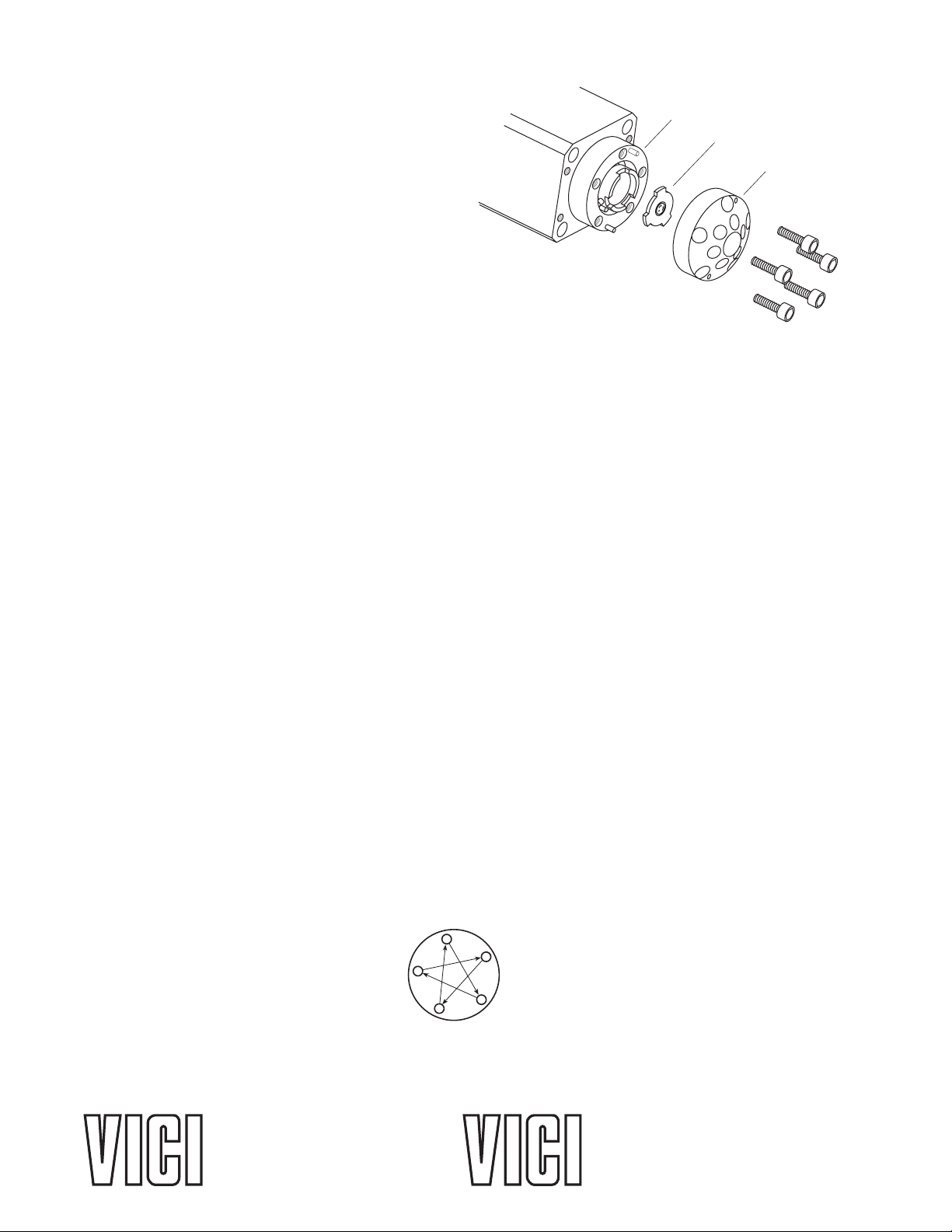
Figure 9:
Exploded view of a
typical injector
Cleaning and Rotor Replacement
These valves have polished sealing surfaces
which must be protected during any disassembly
or cleaning procedure. Work in a clean environ-
ment and always set parts on a soft tissue or clean
paper. Cleaning a valve can often be accomplished
by flushing all the lines with appropriate solvents.
Do not disassemble the valve unless system
malfunction is definitely isolated to the valve.
Disassembly (Refer to Figure 9)
1. Use a 3/32" hex driver to remove the 5-40 socket
head screws that secure the stator to the valve body. Alternate among the five screws in the sequence
indicated in Figure 10, loosening them in quarter-turn (90°) increments until all load is removed.
2. To ensure that the sealing surface of the stator is not damaged, rest it on its outer face. Or, if the
tubing is still connected, leave it suspended by the tubing.
3. With your fingers or a small tool, gently pry the rotor away from the driver.
4. Examine the rotor sealing surface for scratches. If you see any, the rotor should be replaced.
5. Examine the stator sealing surfaces. If scratches are visible between the ports, that part should be
replaced or resurfaced. Call VICI for help in determining if resurfacing is feasible.
6. Clean all the parts thoroughly with an appropriate solvent, taking care that no surfaces get scratched.
(A common problem with HPLC is the formation of buffer crystals, which are usually water-soluble.)
It is not necessary to dry the rotor.
Reassembly
1. Replace the rotor in the driver, making sure that the rotor sealing surface with its engraved flow
passages is facing out. The tabs on the rotor have an asymmetrical pattern to prevent assembly
with improper orientation.
2. Replace the stator. Insert the five socket head screws and tighten them gently until they start to get
snug. Alternate among the five screws in the sequence indicated in Figure 10, tightening them in
quarter-turn (90°) increments until the stator is flush against the valve body.
Do not overtighten the screws – they simply hold the assembly together and do not affect the seal-
ing force, which is automatically set as the screws pull the stator against the valve body.
3. Test the valve by pressurizing the system. If it doesn’t hold pressure, the valve should be returned
to Valco for repair.