VICKING WORKmate II User manual

WORKmate II
USER MANUAL
VICKING electronics
B-3583 Paal-Beringen
Schemkensstraat 6
Tel: +32/11/450.590
Fax: +32/11/450.591
E-mail: [email protected]

Vicking electronics Pag. 2
Overview
Introduction
The WORKmate II is a cost effective data capture terminal for connection to the Vicking Electronics
concentrator network.
It can be used for:
a. Real-time job control, at every workstation, the appropriate information can be entered by the
operator, using the keyboard or the attached barcode reader.
b. Time & attendance applications, the employee can identify himself with a proximity key and request
information with the function keys.
c. Access control applications, a proximity key or card is used to grand access, the relays opens a door,
the keyboard can be used to enter a password.
Technical specifications
•New stylish housing which you can use as a table or wall model by rotating the top cover.
•Dimensions: Width 113mm Length 235mm Depth 94mm
•Weight: 450 gram
•LCD display with 4 lines of 16 characters with backlighting.
The characters are 5.5 mm high.
•Splash water proof membrane keyboard with 4x9 keys. (36 keys total)
•Reads 2/5 interleaved, code 39, UPC and EAN bar-codes.
•Two switch inputs.
•Two Transistor outputs.
•2 LED’s (red, green).
•Built-in beeper with different tones.
•Connection to the concentrator network via RJ 45 or a screw connector.
•Full RS232 serial port.
•The following readers can be connected to the WORKmate:
•An internal proximity card reader
•An external proximity card reader
•Two barcode wand or CCD barcode readers.
•Two magnetic card readers (ISO track 2)
•External power needed: From 8V to 24V DC
•Optional I/O board
•Two relays
•Two opto-isolated inputs with counter possibility.
•A opto-isolated proximity reader.
•DIN connector to the concentrator network.
•Screw connector to the concentrator network.

Vicking electronics Pag. 3
Power supply
The WORKmate II draws more power than the old WORKmate 36,
If you switch on the extra hardware in the workmate it can be 3 to 4 times more.
However the WORKmate II has a switching power regulator which uses the available power more
efficiently, also this new regulator will reset the WORKmate if the power drops below the minimum for a
short time, this prevents that the microprocessor will hang-up.
Power consumption of WORKmate elements
Workmate 0.5 W
Each relay 0.2 W
Active backlight 0.15 W
Barcode wand 0.15 W
CCD scanner active 0.8 W
CCD scanner standby 0.3 W
The powersupply for the WORKmates can supply about 30 Watts of power,
take into account that a part of this power is lost in the cables, the longer the cable the more power is lost.
The WORKmate II can measure the voltage on the powerlines, the more this voltage drops the more is lost in
the cables. If the voltage becomes to low (lower than 9V) you must use an extra powersupply.
Workmate II hardware
Network connection
The terminal must be connected to a Vicking concentrator network, the RJ45 connector on the outside or the
screw connector on the inside can be used for this. The I/O board features a DIN connector to connect to
the concentrator network.
Attention! The RJ45 connector is the same type that is used in Ethernet networks, be careful not to connect
the WORKmate II to an ethernet network. We have chosen this type of connector because of lot of people
know how to install Ethernet networks and have the right tools.
The WORKmate also draws its power from the network, it uses 6 wires 2 for data transmission, 2 for data
reception and 2 for power.
All the WORKmates on 1 line are connected in parallel to the network cable. Each WORKmate needs a
unique address to differentiate them from each other, this address is show when the WORkmate starts-up.
You can change the address in the settings menu.
You can connect up to 4 lines with maximum 63 WORKmates to the concentrator. The WORKmates on a
line must have different addresses, between the lines the addresses can be the same. If you have a network
with less that 63 WORKmates, it is better the give all WORKmates unique addresses, so there will be no
problem when switching WORKmate from one line to another.
Barcode readers
The WORKmate can decode 2/5 interleaved, code 39, UPC and EAN bar-codes.
You can connect a barcode pen, CCD reader or barcode badge reader, 2 barcode readers can be used at the
same time.
There are 3 connectors in the WORKmate that you can used for barcode readers:

Vicking electronics Pag. 4
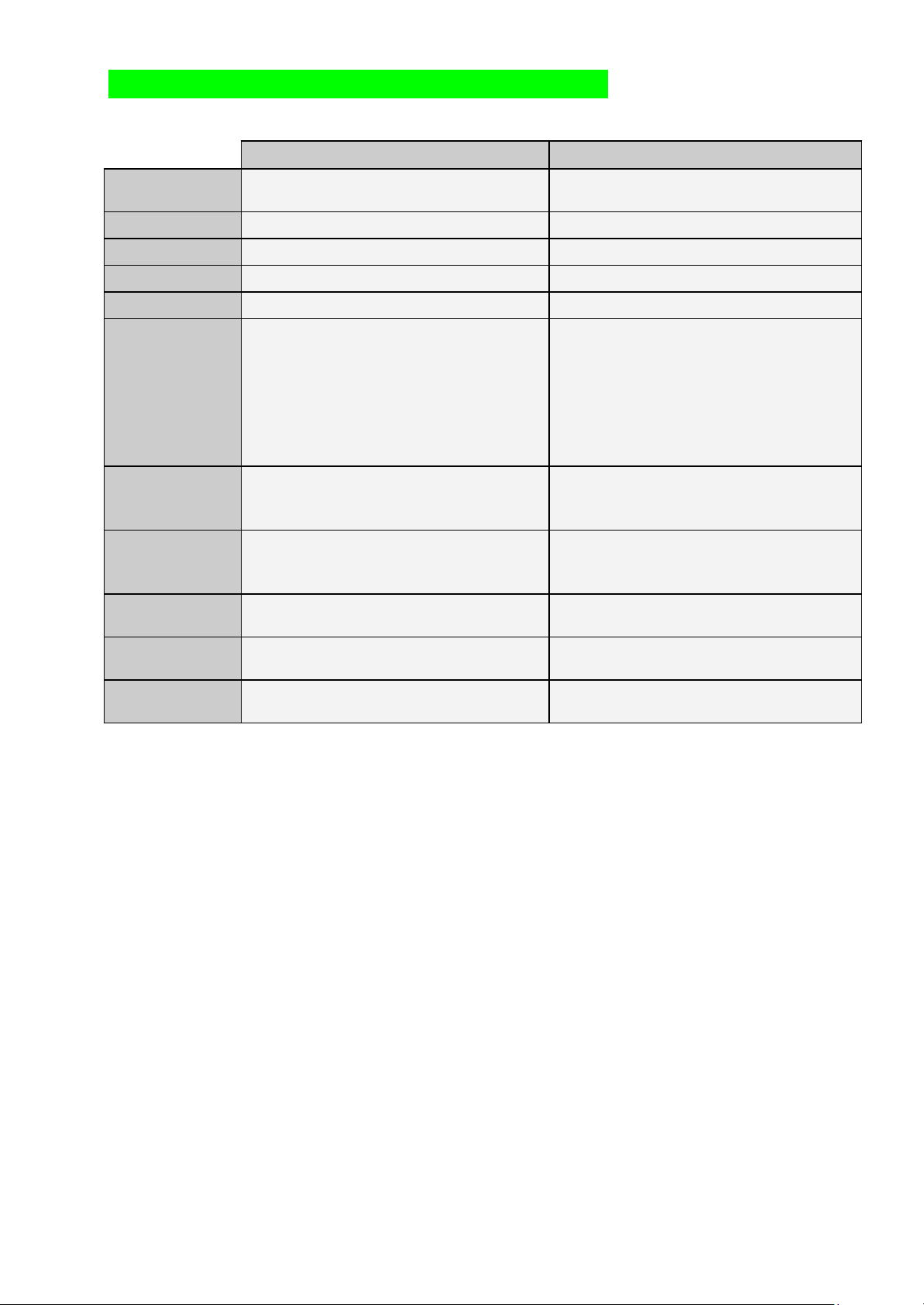
Barcode port 1 Right DIN connector In the default setting the right and left DIN connector gives the
same software code, so the user can choose where he plugs in
the barcode reader.
Left DIN connector Can be programmed to give a different software code as the
right connector if the application demands it.
Barcode port 2 Internal molex connector Can’t be used if the left DIN connector is also used.
This connector is used if you want to prevent the user from
easily disconnecting the barcode reader.
Proximity / magnetic card readers
The workmate can read magnetic cards that have data on track2
in accordance with the international standard ISO 2 ABA.
Character encoding: 4 bits plus a parity bit.
Track encoding: START(13) DATA END(15) LRC maximum 38 characters.
The magnetic card readers and the proximity readers both use the same protocol and the same connectors,
but some connections are reserved only for proximity.
There are 2 ways to connect a magnetic card reader to the WORKmate:
Prox. port 1 Internal molex connector If the reader must be permanently connected to the
WORKmate.
Prox. port 2 Left DIN connector The installation is easier through this connector, but can be
disconnected by the user.
Both connections can be used at the same time.
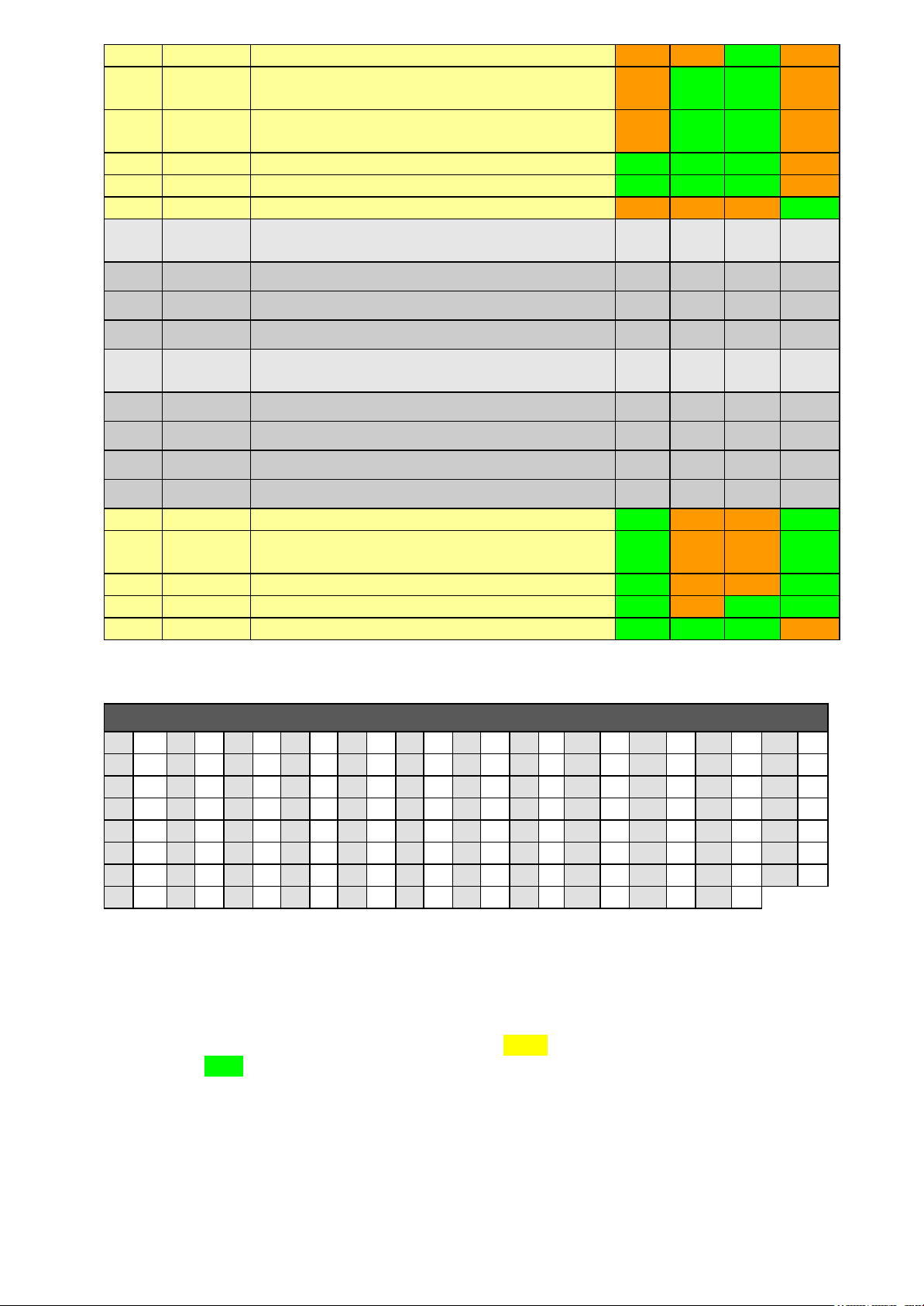
There are 4 ways to connect a proximity reader to the WORKmate:
Internal proximity reader A proximity module can optionally be mounted directly on the
WORKmate mainboard.
Prox. port 1 Internal molex connector To connect to an internal proximity board. Or an external
proximity reader a short distance from the WORKmate that
can’t be disconnected easily.
Left DIN connector You can connect an external proximity reader a short distance
from the WORKmate via the left DIN connector.
Prox. port 2 Opto-coupled interface
on the I/O board If you want to connect an external proximity reader a long
distance from the WORKmate you need to install the extra I/O
board.
Both port can have a reader connected at the same time.
Like the barcode readers, you can setup the ports to generate the same or a different software code.
Input / Output
Each DIN connector has one output pin. These outputs are not buffered with a relays, they are directly
connected to the WORKmate transistors. These outputs are used in special interfaces connected to the
WORKmate.
You need the I/O board if you want more powerful outputs.
Each DIN connector has an input pin, you must connect a switch to these inputs (from ground pin 2 to the
input pin 7). The inputs are only meant to detect if a switch in on or off. Do not connect an external voltage to
the input pins. You need the I/O board if you want more powerful inputs.

Vicking electronics Pag. 5
The input of the right DIN connector also can be programmed to emulate one key on the keyboard, see the
settings chapter. If you press on a external switch, the WORKmate transmits a function code just as if you
pressed it on the keyboard. This can be used for example in a job control application, the user hits the switch
every time a piece or batch is produced.
Audio / Visual
The beeper in the WORKmate II can be programmed to give beeps of various durations and frequencies, to
make a difference for example between a correct data entry or a wrong one. If you want a louder sound,
you can connect a loudspeaker to the main PCB. Connect a small loudspeaker like you find in PC’s to
CON11.
A red and a green LED can be switched on or off or set to blink, this is the most handy in noisy
environments.
The LCD display has 4 lines of 16 characters and has a backlighting that can be used in three modes
1. Always switched off (the default setting)
2. Always switched on
3. Automatic mode. The backlight switches off if no key is pressed for a while.
Serial line
The WORKmate II has standard a full RS232 serial line on board, this can be used to connect a printer or an
external display.
The baudrate can be set to 1200, 2400, 4800 and 9600 baud.
The protocol can be set to 8 no parity, 7 even parity and 7 odd parity.
The RS232 port is also used to program the firmware of the WORKmate.
With the following procedure you can update the software in the WORKmate.
1. Open the WORKmate and disconnect if from the power supply (the network connector)
2. Close the jumper beside the DIN connector that says “CLOSE=PROGAM”
3. Connect a serial cable from the right DIN connector (con7) to the serial port of a PC
4. Reconnect the power supply, the LCD display will show 1 row of black squares.
5. Use the download program on the PC to reprogram the Flash memory of the WORKmate.
6. Disconnect from power and remove the jumper and the serial cable.

Vicking electronics Pag. 6
Optional I/O board
An optional Input/Output board can be mounted on the bottom part of the WORKmate.
The user can easily connect cables to the I/O board with the screw connectors.
In low cost screw connectors the screw presses down directly on the cable, this can give bad connections
and damage the copper wire. The screws connectors in the WORKmate clamp the copper wire between 2
metal plates for a perfect contact.
The board contains an opto-isolated interface for an external proximity reader.
Opto-isolated means that the signal is transmitted with light not through copper wires, this isolates the 2
circuits and prevent a voltage spike on one circuit to damage the other.
This protection means that the external reader can be placed a long distance away from the WORKmate.
A long distance external reader needs a door-lock interface. This interface takes care of the power for a
door-lock, the power for the reader, relays to open the door and connectors to make the wiring easy.
Readers with a cable shorter than ±2 meters can be connected directly to the WORKmate, if you don’t need
to control a door-lock.
This board has 2 relays:
Relais 1 with a normal open (NO) and a normal closed (NC) contact.
Relais 2 with only a normal open contact (NO).
They are software compatible with the outputs in the DIO20.
Be careful when switching inductive loads with the relays, when the power to a coil is switched off it will
generate a large voltage spike that can burn out the relays contacts.
This board also has 2 opto-isolated inputs:
The inputs can be used to detect an ‘on’ or ‘off’ state or to count pulses (up to 100 pulses a second)
See the control codes for more info about the possibilities of the counters.
They are software compatible with the inputs in the DIO20.
Both inputs are identical and can be configured with 2 jumpers:
1. One jumper in the middle (VOLTAGE)
The input is completely isolated from the WORKmate and has to be activated with a voltage between
5V to 48V.
2. Two jumpers in the sides (SWITCH)
In this configuration the input is protected but not completely isolated from the WORKmate.
You can connect a voltage free switch to the input.
Do not use this setting and connect an external voltage to the input ,it will result in a short circuit.
The I/O board has a DIN connector to connect the WORKmate II to the concentrator network, to be
compatible with WORKmate36. You also can connect a cable directly to the WORKmate with a screw
connector, if for example your cable comes through a wall.

Vicking electronics Pag. 7
Differences with the old WORKmate 36
WORKmate 36 WORKmate II
Display 2 Line 16 characters
no backlight 4 Line 16 characters
with backlight
LED’s No leds Red and green led
Beeper Fixed tone Programmable tone
Firmware Manually change EPROM Download in Flash ROM
Connectors Optional barcode Standard 2 multifunctional connectors
Input / Ouput 1 relays
1 input (no counter)
1 barcode reader
1 proximity reader
2 relays
2 inputs (can count pulses)
2 barcode readers
2 proximity readers
2 Switch inputs
2 Transistor outputs
1 RS232 port standard
Badge readers Special mode for badge readers
The inputs and communication are
shut-down in this mode
No special mode for badge readers
The whole WORKmate stays functional.
Concentrator
Network Connection with DIN connector Connection with RJ-45
With DIN or direct cable connection
on the I/O board
Power Very low power consumption.
Linear power regulator WORKmate draws more power.
Switching power regulator
Housing Simple housing needs accessories to
mount. Design housing easy to mount on the wall or
place on the table.
Settings With DIP switches With a menu, the parameters are stored in
flash memory.

Vicking electronics Pag. 8
1.Software
To change the setting in the previous WORKmate, you needed to open de WORKmate and change dipswitch
settings. In the WORKmate II, all the parameters are stored in flash memory, which you can change directly
on the WORKmate with keyboard, see the chapter about ‘the settings menu’.
New firmware versions are up loadable by PC to flash memory (No more difficult EPROM changing’s).
The WORKmates hardware can be tested with a build in self-test menu, including measurement of the input
voltage on the network cables.
When the WORKmate is unable to send data to the concentrator, the error message ”Communication
time-out error!” appears and the transmission is aborted. The WORKmate 36 would keep waiting till the
concentrator responds, the result is that the WORKmate 36 doesn’t react to anything.
The old WORKmate 36 needed to go to a special mode when you wanted to read a magnetic card or a
barcode, because of the limitations of the micro-processor. The workmate II has a more powerful 16 bits
processor, so no special mode for barcode or magnetic input is necessary. In the WORKmate II the readers
are always active, so the software needs to take this into account, for compatibility with older software you
can switch the Barcode & Prox. reader mode to SOFTWARE ENABLED in the setting menu.
The software codes of the WORKmate II are compatible with the WORKmate 36 codes, there are some
additional commands for the new hardware functionalities. The DIO-20 was a separate terminal without
keyboard and display for counting pulses and driving relays outputs. All software functionalities of the DIO-20
are also built in the WORKmate II, for the hardware you need the optional I/O board.

Vicking electronics Pag. 9
The terminal command codes
The WORKmate is a dumb terminal, it can not function by itself, a remote program controls it though
command codes. The WORKmate responds with function codes and input data.
This chapter describes the command codes, for the codes transmitted by the WORKmate see the chapter
“The terminal output function codes”.
You can send 2 types of data to the terminal:
1) Readable text that is displayed from the current cursor position.
If the end of a line has been reached, the cursor will not go to the next line, you need to reposition the
cursor with the ‘Position cursor’ command, otherwise the following characters will not be displayed.
2) Command codes that activate special actions.
The table below shows the following information:
§If the ASCII code is a command or a displayable character
§A description of the command
§For each command there is an indication what type of WORKmate supports it.
o W.M. II : The newest WORKmate which this manual is about.
o W.M. 36 : The older WORKmate in a small low cost housing, with 36 keys
o W.M. 24 : A WORKmate in a large waterproof housing, with a larger display and 24 keys.
o DIO20 : A WORKmate type terminal without display and keys, with two outputs and counter
inputs.
o
ASCI
IType Comment W.M.
II W.M.
36 W.M.
24 DIO
20
0Command
1Command
2Command Timebase real time clock YYYN
3Command Activate read time clock display YYYN
4Command Input 1 active detect YYYY
5Command Input 1 inactive detect YYYY
6Command Universal output (+1 or 2 parameter byte) YNNN
7Command Beeper YYYN
8Command Relays 1 on YYYY
9Command Relays 1 off YYYY
10 Command Relays 2 on YNYY
11 Command Relays 2 off YNYY
12 Command
13 Command
14 Command Input 2 active detect YNYY
15 Command Input 2 inactive detect YNYY
16 Command Activate barcode mode YYNN
17 Command Time out (+2 parameter bytes) YYYN
18 Command Save cursor position YYYN
19 Command Restore cursor position YYYN
20 Command
21 Command Activate magnetic card mode YYNN
22 Command Relays 1 timed (+1 parameter byte) YYYY
23 Command Relays 2 timed (+1 parameter byte) YNYY
24 Command
25 Command Input in security mode YNYN

Vicking electronics Pag. 10
26 Command Start executive protocol for vending machines NNYN
27 Command Cursor normal
Use universal output in the WORKmate II NYYN
28 Command Cusor blink
Use universal output in the WORKmate II NYYN
29 Command Clear screen YYYN
30 Command Position cursor (+1 parameter byte) YYYN
31 Command Request all input levels NNNY
32 to
90 Character These standard ASCII characters (space to Z) are
displayed on the LCD of the WORKmate
91 Character The ASCII character [is shown as Ä
92 Character The ASCII character \is shown as Ö
93 Character The ASCII character ] is shown as Ü
94 to
122 Character These standard ASCII characters (^ to z) are
displayed on the LCD of the WORKmate
123 Character The ASCII character { is shown as ä
124 Character The ASCII character | is shown as ö
125 Character The ASCII character } is shown as ü
126 Character The ASCII character ~ is shown as ß
123 Command Reset a counter (+1 parameter byte) YNNY
124 Command Set upcounter 1 with timeout (+5 parameter bytes)
Preset a counter (+9 parameter bytes) YNNY
125 Command Read counter YNNY
126 Command Read level inputlines directly (+1 parameter byte) YNYY
127 Command Send to extra serial line YYYN
Table of all the displayable characters of the WORKmate
32 SP
40 (48 056 864 @72 H80 P88 X96 `104 h112 p120 x
33 !41 )49 157 965 A73 I81 Q89 Y97 a105 i113 q121 y
34 “42 *50 258 :66 B74 J82 R90 Z98 b106 j114 r122 z
35 #43 +51 359 ;67 C75 K83 S91 Ä99 c107 k115 s123 ä
36 $44 ,52 460 <68 D76 L84 T92 Ö100 d108 l115 t124 ö
37 %45 -53 561 =69 E77 M85 U93 Ü101 e109 m117 u125 ü
38 &46 .54 662 >70 F78 N86 V94 ^102 f110 n118 v126 ß
39 ‘47 /55 763 ?71 G79 O87 W95 _103 g111 o119 w
The WORKmate can be connected to an online or offline concentrator.
The online-concentrator only manages the network, the computer connected to it has the application program
that controls the WORKmates. The ONLINE example given with each command shows the data that the
computer has to send to achieve the desired effect. Each yellow number block represents a command code
of 1 byte, the green text are display characters.
The offline-concentrator manages the network and can run an application program written in VIPRO.
VIPRO is a basic like language to control VICKING electronics devices, see the VIPRO manual for more
information.

Vicking electronics Pag. 11
Data is placed in a buffer with the PRINT command and transmitted with the SEND command. Most codes
to the terminals can be automatically generated by using the parameter file ( TXT ) this is shown under the
heading “OFFLINE parameter example”.
The codes can also be directly inserted in the transmission string, this is shown under the heading “OFFLINE
direct example”.
Relay 1 on
8(dec)
Relay 1 becomes active.
The normal open contact is now closed and the normal closed contact will be open.
The I/O board must be installed for this command to be effective.
ONLINE example
Transmit: 29Relay 1 on08
Clear screen, display ‘Relay 1 on’ , switch relay 1 on
OFFLINE direct example
CHAIN $RELON%8
PRINT $ADRES,$RELON : SEND
OFFLINE parameter example
PRINT $ADRES : POINT 1,1 : SEND
Relay 1 off
9(dec)
Relay 1 becomes inactive.
The normal open contact is now open and the normal closed contact will be closed.
The I/O board must be installed for this command to be effective.
ONLINE example
Transmit: 29Relay 1 off09
Clear screen, display ‘Relay 1 off’ , switch relay 1
off
OFFLINE direct example
CHAIN $RELON%9
PRINT $ADRES,$RELON : SEND
OFFLINE parameter example
PRINT $ADRES : POINT 1,2 : SEND

Vicking electronics Pag. 12
Relays 1 timed
22(dec) + timecode
Relay 1 becomes active for a time defined by the ‘timecode’ byte, then it switches off again and the
WORKmate sends a function code back so that the application program knows that the WORKmate is ready
to be used again. See the chapter “The terminal output function codes”.
The timecode byte is in units of 0.5 sec and can have a value of 1 to 127.
ONLINE example
Transmit: 29Relay 1 puls22 10
Clear screen, display ‘Relay 1 puls’
, puls relay 1 for
5 seconds
OFFLINE direct example
CHAIN $RELON%22%10
PRINT $ADRES,$RELON : SEND
OFFLINE parameter example
Field 3 in a TXT file record contains the timecode
TXT record 5: 000010
PRINT $ADRES : POINT 5,3 : SEND
Relay 2 on
10(dec)
Relay 2 becomes active.
The normal open contact is now closed.
The I/O board must be installed for this command to be effective.
ONLINE example
Transmit: 29Relay 2 on10
Clear screen, display ‘Relay 2 on’ , switch relay 2 on
OFFLINE direct example
CHAIN $RELON%10
PRINT $ADRES,$RELON : SEND
OFFLINE parameter example
Is not possible with parameters
Relay 2 off
11(dec)
Relay 2 becomes inactive.
The normal open contact is now open.
The I/O board must be installed for this command to be effective.

Vicking electronics Pag. 13
ONLINE example
Transmit: 29Relay 2 off11
Clear screen, display ‘Relay 2 off’ , switch relay 2
off
OFFLINE direct example
CHAIN $RELON%11
PRINT $ADRES,$RELON : SEND
OFFLINE parameter example
Is not possible with parameters
Relays 2 timed
23(dec) + timecode
Relay 2 becomes active for a time defined by the ‘timecode’ byte, then it switches off again and the
WORKmate sends a function code back so that the application program knows that the WORKmate is ready
to be used again. See the chapter “The terminal output function codes”.
The timecode byte is in units of 0.5 sec and can have a value of 1 to 127.
ONLINE example
Transmit: 29Relay 2 puls23 08
Clear screen, display ‘Relay 2 puls’ , puls relay 2 for
4 seconds
OFFLINE direct example
CHAIN $RELON%23%10
PRINT $ADRES,$RELON : SEND
OFFLINE parameter example
Is not possible with parameters
Simple Beep
7(dec)
The buzzer beeps for .5 seconds.
See the universal output command for more buzzer functions.
ONLINE example
Transmit: 29Error07
Clear screen, display ‘Error’ , give a beep
OFFLINE direct example
CHAIN $BEEP%7
PRINT $ADRES,$BEEP : SEND
OFFLINE parameter example
Make field 2 in a TXT file record, 00=no beep 01=beep
TXT record 5: 170100ENTER ORDER
PRINT $ADRES,-5 : SEND

Vicking electronics Pag. 14
Universal output
6(dec) + Code + [Time]
This command groups together all output functions in one command.
The command is a 2-byte code to expand the amount of possible command codes.
Some commands, like the relay codes, also exist as an older single byte commands. This is for compatibility
with older software.
Some commands require a ‘Time’ parameter they are 3 bytes long.
The codes are grouped together in such a manner that extra commands can be added in the future.
6(dec) , 32(dec) Short beep with low frequency
6(dec) , 33(dec) Short beep with medium frequency
6(dec) , 34(dec) Short beep with high frequency
6(dec) , 35(dec) Medium length beep with low frequency
6(dec) , 36(dec) Medium length beep with medium frequency
6(dec) , 37(dec) Medium length beep with high frequency
6(dec) , 38(dec) Long beep with low frequency
6(dec) , 39(dec) Long beep with medium frequency
6(dec) , 40(dec) Long beep with high frequency
6(dec) , 41(dec) 3 medium length tones direct after each other with rising frequency. This can
be used to attract the attention of the user, during special conditions.
BEEPER
6(dec) , 42(dec) 10 short tones direct after each other with rising frequency. This can be used
to attract the attention of the user, during special conditions.
6(dec) , 48(dec) Switch red LED on
6(dec) , 49(dec) Switch red LED off (is also switched off with clear screen)
6(dec) , 50(dec) Let red LED blink
6(dec) , 51(dec) Switch green LED on
6(dec) , 52(dec) Switch green LED off (is also switched off with clear screen)
LEDS
6(dec) , 53(dec) Let green LED blink
6(dec) , 61(dec) Clear screen without switching off the LED’s
6(dec) , 62(dec) Set LCD display cursor to a blinking block
You can use this function to especially attract attention to the cursor
LCD
6(dec) , 63(dec) Set LCD display cursor to normal, a non blinking underscore.
(is also switched to normal with clear screen)
6(dec) , 64(dec) Relay 1 on
6(dec) , 80(dec) Relay 1 off
6(dec) , 96(dec), Time Relay 1 timed
With extra time byte in units of 0.5 sec, with a value of 1 to 127.
6(dec) , 112(dec) Relay 1 toggle
The relay will continuously go on and off with a cycle of 1.2 second.
This mode is switched off with a clear screen.
6(dec) , 65(dec) Relay 2 on
6(dec) , 81(dec) Relay 2 off
6(dec) , 97(dec), Time Relay 2 timed
With extra time byte in units of 0.5 sec, with a value of 1 to 127.
6(dec) , 66(dec) Output 3 on
6(dec) , 82(dec) Output 3 off
6(dec) , 98(dec), Time Output 3 timed
With extra time byte in units of 0.5 sec, with a value of 1 to 127.
OUTPUTS
6(dec) , 67(dec) Output 4 on

Vicking electronics Pag. 15
6(dec) , 83(dec) Output 4 off
6(dec) , 99(dec), Time Output 4 timed
With extra time byte in units of 0.5 sec, with a value of 1 to 127.
6(dec) , 125(dec) Identify WORKmate model command.
The WORkmate II returns function code 120 with a 4 digit number in the data
field. The first number is always 2 for the WORKmate II, the last 3 digits are
the firmware version number.
See the chapter on output function codes.
ONLINE example
Transmit: 06 50
Red led blinks
OFFLINE direct example
CHAIN $REDBLINK%6%50
PRINT $ADRES,$REDBLINK : SEND
OFFLINE parameter example
Is not possible with parameters
Time out
17(dec) + Time1 + Time2
This command is used as input timeout, for example the program returns to the main menu when the user
wait to long to answer a question. This command can also be used to show a message for a certain time, for
example when the user types in wrong data, a error message is shown after the timeout is elapsed the
program returns to the question.
The workmate sends a function code after both time1 and time2 are elapsed. See the chapter “The terminal
output function codes”.
The time unit of the bytes Time1 and Time2 is half a second, Time1 can have a value of 1 to 127 and Time2
can have a value of 1 to 15.
During the first time ‘Time1’ the workmate is quiet, during the second time ‘Time2’ the workmate will beep
to attract the attention of the user.
When the user pushes a key, reads a bar code or magnetic card the time-out function will be aborted.
ONLINE example
Transmit: 17Input error10 04
Clear screen, display ‘Input error’ , wait for 5 sec
and beep for 2 sec.
OFFLINE direct example
CHAIN $TIMEOUT%17%10%4
PRINT $ADRES,$TIMEOUT : SEND
OFFLINE parameter example
Field 2 in a TXT file record is time1, field 3 is time2
TXT record 5: 001004
PRINT $ADRES : POINT 5 : SEND

Vicking electronics Pag. 16
Clear screen
29(dec)
Clear the entire display and position the cursor at the start of the display.
The red and green LED is also switched off, if you don’t want the clear the LED’s use the clear screen
function in the ‘Universal output’ command.
ONLINE example
Transmit: 29
Clear screen
OFFLINE direct example
CHAIN $CLR%29
PRINT $ADRES,$CLS : SEND
OFFLINE parameter example
Field 2 in a TXT file 00=don’t clear 02=clear screen
TXT record 5: 000200
PRINT $ADRES,+5 : SEND
Position cursor
30(dec) + Pos
Position the cursor on the screen.
The values for the position code Pos are shown in the following table:
Columns
64 65 66 67 68 69 70 71 72 73 74 75 76 77 78 79
80 81 82 83 84 85 86 87 88 89 90 91 92 93 94 95
96 97 98 99 100 101 102 103 104 105 106 107 108 109 110 111
Rows
112 113 114 115 116 117 118 119 120 121 122 123 124 125 126 127
ONLINE example
Transmit: 17Row 130 80Row 2
Clear screen, display ‘Row 1’,Position cursor on row 2
, display ‘Row 2’
OFFLINE direct example
CHAIN $POS2%30%80
PRINT $ADRES,$POS2 : SEND
OFFLINE parameter example
Field 1 in a TXT file contains the position code
Row 1: 01 to 16
Row 2: 17 to 32
Row 3: 33 to 48
Row 4: 49 to 64
TXT record 5: 170000
PRINT $ADRES,+5 : SEND

Vicking electronics Pag. 17
Send data to RS232 port
127(dec) + Data string
The WORKmate sends the Data string on the RS232 serial port of the WORKmate.
The baud rate and the protocol of the RS232 port can be set in the setting menu.
The 127 code is followed by the data to be transmitted, the data can not be longer than 95 bytes.
After the 127 code no other workmate commands can be used only data to be transmitted.
After the complete data is transmitted the workmate will respond with a function code , so the software can
execute the next task for the workmate. See the chapter “The terminal output function codes”.
The characters in the Data string must be between 1 and 127.
The code 13(dec) (Carridge return) can’t be used, the online protocol uses 13 as a block terminator.
Use 1(dec) instead, this will be translated to 13 before it is transmitted on the RS232 port.
Long strings of the same characters can be transmitted shorter with this 3 byte code:
2(dec) , Repeat amount + 31 , ASCII code of character
For example a string of 40 times a minus ‘-‘character 2(dec) 71(dec) 45(dec)
ONLINE example
Transmit: 127Total time01 10 02 71-
Send to serial line command, send text ‘Total time’,
Carriage return, Line feed, send 40 times ‘-‘
OFFLINE direct example
CHAIN $SERIAL%127
CHAIN $CRLF%1%10
PRINT $ADRES,$SERIAL,”PRINT TEST”,$CRLF : SEND
OFFLINE parameter example
Is not possible with parameters
Real time clock display
2(dec) and 3(dec)
A workmate has no real time clock, if you want to show the current time and date on the workmate display it
has to be transmitted repeatedly.
Because it would be difficult to program this in VIPRO the concentrator takes care of this.
The codes described below are generated automatically in an off-line concentrator by the VIPRO language.
In an on-line concentrator you have to send them yourself.
3 (dec) activate read time clock display :
With this command you prepare the WORKmate to display the time and date in a certain way.
The settings are cleared when you clear the screen or when a data input is finished on the WORKmate.
For example you want to see the time in the main menu of an application program. Every time the main
screen is send to the WORKmate you also have to send this command, in the sub-dialogs where you don’t
want to see the time, you don’t send this command.
This command has 2 variations.

Vicking electronics Pag. 18
1) Time and date display. The time and date received through command 02 is shown on the display after
formatting.
3(dec),43 (dec),format, timeposition, dateposition
format sets the way the time and date are formatted on the LCD display.
48 (dec) = HH:MM:SS DD/MM/YY
49 (dec) = HH:MM DD/MM/YY
50 (dec) = HH:MM:SS DD/MM
51 (dec) = HH:MM DD/MM
52 (dec) = HH:MM with large characters, only line 4 is free for additional text.
The date is not shown. The position parameter is ignored.
timeposition sets the position of the time on the display. (can’t be 0)
dateposition sets the position of the date on the display. (0 disables display of the date)
For the possible position values see the table include with the Position cursor code.
Example: 3 43 48 64 0 sets the time on the first line with the format HH:MM:SS and doesn’t
displays the date.
2) Alarm time countdown. The time received through command 02 is subtracted from the set alarm time.
You get a counter that counts down to zero to the set alarm time. If zero is reached the workmate will
respond with a function code. See the chapter “The terminal output function codes”. This is used with
job registration, the alarm time is set to the time that the job should normally be finished.
After zero the alarm time can go negative so you know the overtime for a job.
3(dec),45 (dec),format, timeposition, HHMMSS
format sets the way the alarm counter is formatted on the LCD display.
48 (dec) = HH:MM:SS No negative values, counter stops at 00:00:00
49 (dec) = MM:SS No negative values, counter stops at 00:00
50 (dec) = HH:MM:SS With negative values
51 (dec) = MM:SS With negative values
52 (dec) = HH:MM With large characters, only line 4 is free for additional text.
With negative values. The position parameter is ignored.
timeposition sets the position of the alarm counter on the display. (can’t be 0)
HHMMSS alarm time
2 (dec) timebase real time clock :
2 (dec) HHMMSSDDMMYY
The command is followed by a 12 numbers that represent the current Hour Minute Second Day Month Year.
With this command the current time and date is transmitted to all the WORKmates.
Only the WORKmate that are prepared with the command 03 will use this information to display the time or
and alarm counter.
This command is always send with a public address and you have to repeat it after a set time. If you don’t
need to display the seconds you can send this command every minute.
ONLINE example
Transmit: 03 43 48 64 80
Display the time on line 1 and the date on line 2
Transmit: 02123000123001
Send current time (12:30:00) and date (30 December
2001)
OFFLINE direct example
Is not possible with direct codes

Vicking electronics Pag. 19
OFFLINE parameter example
A complete record in the TXT file contains all settings
The timebase is transmitted automatically every 4 sec.
after the first use of the ‘/’ parameter in the print
instruction.
TXT record 5: 011700
PRINT $ADRES,/5 : SEND
Activate reader mode
21(dec) 16(dec)
In the old WORKmates the readers are only active in a special mode. These commands (21 for proximity &
magnetic cards, 16 for barcodes) are used in the WORKmate 36 to switch on the reader mode.
The new WORKMATE II is always ready to read barcodes or proximity cards, you don’t have to use these
codes anymore. Be careful when programming an application, it is now possible that you read a barcode in an
input that doesn’t need barcodes. You must now test for reader data in every input and discard it new you
don’t need it.
To be compatible with older software you can set the mode to ‘SOFTWARE ENABLED’, in this mode the
readers are only active if they are activated by these codes. See ‘Barcode & Prox. reader mode’ in the setup
menu.
ONLINE example
Transmit: 29Read barcode16
Clear screen, display ‘Read barcode’, Activate barcode
OFFLINE direct example
CHAIN $BARCOD%16
PRINT $ADRES,$BARCOD : SEND
OFFLINE parameter example
Make field 3 in a TXT file record 00=no reader
01=barcode 02=proximity
TXT record 5: 170101Read barcode
PRINT $ADRES,-5 : SEND
The input port commands
The 2 inputs on the Input/Output board can be used with the following methods. It depends on the application
which method is the best.
§Read out the input levels directly.
Use this when you don’t want to know when the change occurs, but just the current status.
§The workmate waits for a change on the input line after it receives one of the ‘input detect‘
commands. Use this if you know when the input needs to change and you want to limit the amount of
function codes the WORKmate transmits.
§Let the workmate send a function code automatically, during every change on the input line.
Use this if you don’t know when the input is going to change. The chance that you miss input data is
smaller with this method. Don’t use this method on a device that can generate of lot of pulses, you
can overwhelm the concentrator network with the constant transmission of input change codes.
This mode is switched off by default, see ‘input port 1 message mode’ in the setup menu how to
activate it.

Vicking electronics Pag. 20
§Let the workmate count the pulses on an input port. See the counter commands.
This is useful for counting production amounts. For example: when a person starts working on an
order the counter is reset, when the person indicates that he stops working the counter is read and the
production amount is known.
Input 1 active detect
4(dec)
The WORKmate sends a function code when input 1 on the Input/Output board becomes active, if input 1
already was active when this command was received, the function code is send immediately. See the chapter
“The terminal output function codes”.
Input 1 is active when current flows through the opto-coupler in voltage mode or when the switch is closed in
switch mode.
This command is not reset by any other command, it stays active till the input changes or the ‘input 1 inactive
detect’ command is send.
ONLINE example
Transmit: 04
Wait till input 1 becomes active.
OFFLINE direct example
CHAIN $IN1LOW%4
PRINT $ADRES,$IN1LOW : SEND
OFFLINE parameter example
Is not possible with parameters
Input 1 inactive detect
5(dec)
The workmate sends a function code when input 1 on the Input/Output board becomes inactive, if input 1
already was inactive when this command was received, the function code is send immediately. See the
chapter “The terminal output function codes”.
Input 1 is active when no current flows through the opto-coupler in voltage mode or when the switch is open
in switch mode.
This command is not reset by any other command, it stays active till the input changes or the ‘input 1 active
detect’ command is send.
ONLINE example
Transmit: 05
Wait till input 1 becomes inactive.
OFFLINE direct example
CHAIN $IN1HIGH%5
PRINT $ADRES,$IN1HIGH : SEND
OFFLINE parameter example
Is not possible with parameters
Table of contents
Other VICKING Touch Terminal manuals