Vicon IQeye Alliance-mx User manual

1
IQeye Alliance-mx
Vandal-Resistant IP Camera
Installation and Operating Instructions

2
Contents
1 Unpacking 3
2 Service 3
3 Description 4
4 Installation 4
5 Parts List 4
6 Mounting Options 5
7 Removal of Dome Cover 6
8 Mounting the Enclosure, Camera, and Lens Assembly 6
9 Connect Camera 8
10 Camera Positioning, Field-of-View Set-up and Focus 8
11 Complete the Dome Camera Installation 9
12 PC Configuration of Alliance-mx 9
13 Factory Reset 10

3
1 Unpacking
Unpack carefully. This is an electromechanical device and should be
handled carefully. Check to ensure the following items are included:
> Alliance-mx Dome Camera Assembly
> Torx T-20 Security Wrench
> 3/4” NPT Plug (installed in the side NPT mount of the enclosure)
> Mounting Hardware
> Lens Cover
> IQtools CD-ROM
2 Service
If the unit needs repair service or parts, the customer should contact
Vicon Industries for authorization to return, as well as shipping
instructions. Refer to Shipping Instructions at the end of this manual.

4
3 Description
Alliance-mx dome cameras provide exceptional image quality in the
most demanding indoor/outdoor environments. With support for up
to 5MP resolution, the Alliance-mx uses Main profile H.264 to deliver
exceptional high-definition clarity at up to 30 frames-per-second.
Simultaneous H.264 and MJPEG video streaming offers flexibility to
optimize live viewing and recording while providing access to video for
other applications.
The Alliance-mx camera features on-camera storage, built-in IR, WDR
(1, 2 and 3MP models) and true day/night capabilities. Made from cast
aluminum with a polycarbonate bubble the Alliance-mx is IP66 (NEMA
4) rated. The included varifocal lens offers flexibility so the Alliance-mx
camera can be installed almost anywhere. There is a choice of manual
or motorized varifocal lens.
4 Installation
NOTE: This manual describes how to install the Alliance-mx camera system, and details interior/exterior
wall and ceiling surface mounting options. Installations should be performed by qualified service
personnel only in accordance with local and national code(s).
5 Parts List
The following depicts the parts included (Figure 5.1):
1. Alliance-mx enclosure, camera, and lens assembly
2. Alliance dome cover and shroud assembly
Figure 5.1

5
6 Mounting Options
The Alliance-mx camera is designed to be used in one of the following
configurations.
NOTE: If the Alliance-mx is to be installed on a hard surface that prohibits direct access to cabling, the
optional IQM-BOX, which includes the IQA-CAB, must be used. If the surface allows running cables directly
to the camera dome, such as a drop ceiling, the optional IQA-CAB only can be used for the audio in/out, I/O
relay, and analog video output if needed.
1. Surface mounted to a durable ceiling surface.
2. Surface mounted to any interior durable wall surface.
3. Mounted to the optional interior/exterior wall mount adapter.
4. Mounted to the optional back box adapter.
NOTE: This guide covers installation of an Alliance-mx dome camera without the optional wall or pendant
mount adapters (IQM-WM3 or IQM-PND). For guidance on mounting the Alliance-mx to the wall or pendant
mount adapters, consult the appropriate accessory’s manual.
WARNING: When installing the Alliance-mx dome camera outdoors, the camera should not
be mounted directly to a wall surface. When mounting outdoors to a wall surface, the IQM-
WM3 (Alliance Series Wall Mount) is required (Figure 6.1).
The Alliance-mx camera provide the following connection options
(Figure 6.2).
1. Ethernet (Power-over-Ethernet) connector.
2. Micro SD card slot (Micro SD card not included)
3. Audio in/out, I/O relay and analog video output (requires optional IQA-CAB);
see section 9 for connection details.
Ethernet (Power-over-Ethernet) Connector
Micro SD card slot
Audio In/Out-I/O Relay-Analog Video Output
Connector
Figure 6.2
Figure 6.1

6
7 Removal of Dome Cover
1. Using the supplied Torx T-20 security wrench, loosen the three tamper-proof
screws holding the dome cover to the enclosure assembly (Figure 7.1). These
screws are captive (held to the dome cover) and should not be removed from
the dome cover trim ring.
2. Lift the dome trim ring with shroud away from the camera assembly.
8 Mounting the Enclosure, Camera, and Lens Assembly
Mounting to masonry or other durable surface wall, ceiling or overhang
with cables routing through the wall or ceiling.
1. Select an appropriate position for the camera and drill the mounting holes and
cable pass through hole.
2. Route the network cable through the wall.
3. Gently push the Ethernet cable through the gasket installed in the enclosure.
Pull enough cable through the gasket to attach an RJ-45 network connector,
and to allow the network connector to plug into the Ethernet socket
(Figure 8.1).
It may be necessary to pierce a hole in the gasket with an Awl tool (not supplied).
NOTE:
• Do not cut the gasket with a knife.
• Do not force the Ethernet cable with connector through the gasket.
• Only pass one cable through the supplied gasket.
Figure 8.1
Figure7.1
Figure 8.2

7
4. To ensure the gasket is sealed gently pull back on the Ethernet cable before
mounting the enclosure to the wall or ceiling.
5. Attach the enclosure to the wall or ceiling by
tightening the four screws with sealing washers
(Figure 8.4).
NOTE: Be sure to use the supplied screws and sealing washers.
Alternative washers will not seal the enclosure from moisture. Extra
sealing washers are supplied.
Mounting to masonry or other durable surface wall, ceiling or overhang with
cables routing along the wall or ceiling for side conduit installation.
1. Select an appropriate position for the camera and drill the mounting holes and
cable pass through hole.
2. Remove the conduit plug from the enclosure. Install a 3/4” (19.1mm) NPT
threaded conduit connector (not supplied) into the conduit hole on the
enclosure.
NOTE: To ensure proper weatherization on the conduit entry, properly seal the conduit threads with
silicon.
3. Pull the Ethernet cable through the conduit and then through the enclosure.
Pull enough cable through the conduit to attach an RJ-45 network connector,
and to allow the network connector to plug into the Ethernet socket.
4. Attach the enclosure to the wall or ceiling by tightening the four screws with
sealing washers.
NOTE: Be sure to use the supplied screws and sealing washers. Alternative washers will not seal the
enclosure from moisture. Extra sealing washers are supplied.
NOTE: When installing the Alliance-mx onto a ceiling tile, use hardware designed to secure the camera
assembly to this surface, and ensure the ceiling tile material is secure.
In addition, follow local regulations and laws that may have specific requirements
governing the installation of security equipment on a ceiling tile surface. Vicon
also strongly recommends the use of a ceiling tile brace and other mounting
hardware designed to secure the Alliance-mx to the ceiling frame infrastructure.
Figure 8.4

8
9 Connect Camera
1. Optional: Insert the Micro SD card in Micro SD
card slot (not supplied).
2. Optional: Route and connect the IQA-CAB cable
when using an external microphone and
powered loudspeaker, I/O relay or analog output
to the Alliance-mx dome camera
as shown in Figure 9.1 (cable and
loudspeaker not supplied).
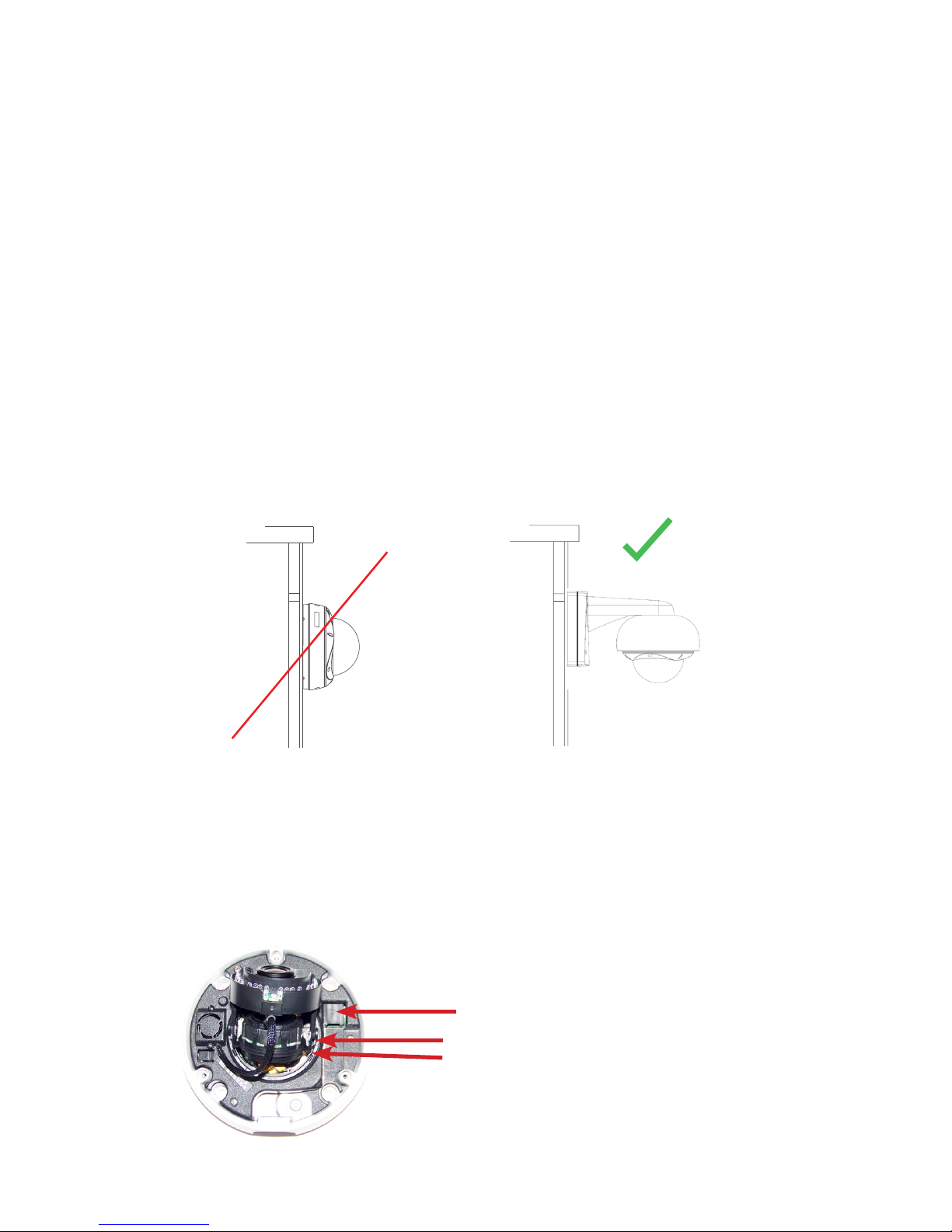
3. Route and connect the Power-over-Ethernet cable to
the Ethernet connector port in the camera as shown
in Figure 9.2.
Cable Connections: Refer to Figure 9.3
Name Function
Mic G/Mic Microphone line in and ground. Externally powered
microphone is recommended for optimal quality.
Line G/Line Audio line out and ground. Powered speaker
required.
Rly 2/Rly 1 Relay output. Relay acts as simple switch between
Rly 1 and Rly 2.
Trg G/Trg Trigger input (senses contact closure)
Vid/Vid G Analog video output. Provides NTSC or PAL signal.
10 Camera Positioning, Field-of-View Set-up and Focus
1. Set the field-of-view using the 3-axis gimbal. Determine camera pan direction
by gripping the camera assembly, and carefully pivot the camera to the viewing
direction.
2. Remove the IR assembly by gently pulling the assembly forward as shown in
Figure 10.1.
3. Adjust the tilt of the camera to the desired viewing angle.
4. On the manual varifocal lens, adjust the field-of-view and focus rings to
achieve the desired focus as shown in Figure 10.2. When finished, tighten the
thumbscrews on the lens. For the motorized varifocal lens, use the camera
interface to set the field-of-view and focus.
NOTE: The manual lens on the Alliance-mx dome camera has a fixed iris and therefore no iris
adjustment is needed.
Figure 9.1
Figure 10.1
Figure 9.2
Optional IQA-CAB
Cable Assembly
for Audio In/Out,
I/O Relay and
Analog Video
Output
Focus Control
Zoom Control
Figure 10.2
Manual Lens only
Figure 9.3

9
11 Complete the Dome Camera Installation
1. Attach the tether from the dome trim ring to the tether mounting point in the
enclosure as shown in Figure 11.1.
2. Rotate the black shroud inside the dome trim ring cover so it aligns with the
camera position.
3. Place the supplied desiccant pack inside the dome as shown in Figure 11.2 to
prevent fogging due to moisture that is present when installing the camera.
Use the supplied cable tie to keep the desiccant from falling down into the
dome bubble.
4. Attach the dome trim ring cover with shroud to the enclosure by tightening the
three tamper-proof screws with the supplied Torx T-20 security wrench.
12 PC Configuration of Alliance-mx
NOTE: The default user name for all IQeye devices is “root” and the default password is “system.”
IQeye cameras are configured for DHCP and will have an IP address assigned if
a DHCP server is on the network. If a DHCP server is not available, the camera
will self-assign an IP address using Automatic Private IP addressing. A static IP
address can be configured using either IQfinder or IQmanager.
Figure 11.1 Figure 11.2

10
1. Download and install IQfinder from the Vicon website. Launch and scan for
camera on the newtork by clicking the refresh button. The detected cameras
will be displayed in the IQfinder window. Select a camera from the list and
click “Assign IP” to edit the selected camera’s network settings. Refer to Figure
12.1.
2. The “Assign IP” window allows the IP address,
Subnet, and Gateway of the camera to be changed
and alternatively the camera to be configured for
DHCP operation. Click the ”Apply” button after
making the desired changes (Figure 12.2).
NOTE: Changing between a static IP address and DHCP will require
the camera to be rebooted.
3. To view a camera, double-click a camera entry
or highlight a camera in the list and click the
“Web Page” button (Figure 12.3). The “Live” page
will be displayed through the default browser (IE
recommended). It is also possible to open Internet
Explorer and enter the IP address of the IQeye
camera in the address field of the browser. If
prompted, install the Active X control (Figure 12.4).
4. To perform further configuration of the camera
click on the “Setup” tab.
NOTE: The default username is “root” and the default password
is “system”.
For additional information and technical
documents, please visit www.vicon-security.com.
13 Factory Reset
1. Press and hold the “Reset” button for 15 seconds as illustrated in Figure 13.1.
Figure 12.1
Figure 12.2
Figure 12.3
Figure 12.4
Figure 13.1

11
Shipping Instructions
Use the following procedure when returning a unit to the factory:
1. Call or write Vicon for a Return Authorization (R.A.) at one of the locations
listed below. Record the name of the Vicon employee who issued the R.A.
Vicon Industries Inc.
135 Fell Court
Hauppauge, NY 11788
Phone: 631-952-2288; Toll-Free: 1-800-645-9116; Fax: 631-951-2288
For service or returns from countries in Europe, contact:
Vicon Industries (U.K.) Ltd
Brunel Way
Fareham, PO15 5TX
United Kingdom
Phone: +44 (0)1489/566300; Fax: +44 (0)1489/566322
2. Attach a sheet of paper to the unit with the following information:
a. Name and address of the company returning the unit
b. Name of the Vicon employee who issued the R.A.
c. R. A. number
d. Brief description of the installation
e. Complete description of the problem and circumstances under which it
occurs
f. Unit’s original date of purchase, if still under warranty
3. Pack the unit carefully. Use the original shipping carton or its equivalent for
maximum protection.
4. Mark the R.A. number on the outside of the carton on the shipping label.

12
Vicon Standard Equipment Warranty
Vicon Industries Inc. (the “Company”) warrants your equipment to be free from
defects in material and workmanship under Normal Use from the date of original
retail purchase for a period of three years, with the following exceptions:
1. All IQEYE Cameras: Two years if purchased before 1/1/2011.
2. Alliance-mini (IQD3xx), Alliance-mx (IQMxxx) and 3 Series (IQ03xx):
Five years if purchased between 1/2/2011 – 12/31/2014.
3. Alliance-Pro (IQA3xx): Five years if purchased between 3/2/2012 –
12/31/2014. Three years if the motorized lens (IQA3xx-A3) option.
4. Uninterruptible Power Supplies: Two years from date of original retail
purchase.
5. VDR-700 Recorder Series: One year from date of original retail purchase.
6. V5616MUX: One year from date of original retail purchase.
7. Arecont Cameras: One year from date of original retail purchase.
8. FMC series fiber-optic media converters and associated accessories: Lifetime
warranty.
9. For PTZ cameras, “Normal Use” excludes prolonged use of lens and pan-
and-tilt motors, gear heads, and gears due to continuous use of “autopan”
or “tour” modes of operation. Such continuous operation is outside the scope
of this warranty.
10. Any product sold as “special” or not listed in Vicon’s commercial price list:
One year from date of original retail purchase.
NOTE:
• If the product is to be used outdoors or in dusty, humid, or other hostile
environments, it must be suitably protected.
• Camera products must be protected, whether in use or not, from exposure
to direct sunlight or halogen light as the light may damage the camera image
sensor. This applies to both indoor and outdoor use of the cameras.
• For camera products supplied without a lens, extreme care should be used
when mounting a lens on these products. Damage to the product due to
incorrectly mounted lenses will invalidate this limited hardware warranty.
• Failure to comply with any of the aforementioned requirements will invalidate
this Limited Hardware Warranty.
Date of retail purchase is the date original end-user takes possession of the
equipment, or, at the sole discretion of the Company, the date the equipment first
becomes operational by the original end-user.
The sole remedy under this Warranty is that defective equipment be repaired or (at
the Company’s option) replaced, at Company repair centers, provided the equipment
has been authorized for return by the Company, and the return shipment is prepaid
in accordance with policy. Repaired or replacement hardware will be warranted for
the remainder of the original Warranty Period or ninety (90) days, whichever is longer.
When a product or part is exchanged the replacement hardware becomes the property
of the original purchaser and all hardware or part thereof that is replaced shall
become the property of Vicon.

13
The warranty does not apply (a) to faulty and improper installation, maintenance,
service, repair and/or alteration in any way that is not contemplated in the
documentation for the product or carried out with Vicon consent in writing, operation
adjustments covered in the operating manual for the product or normal maintenance, (b)
to cosmetic damages, (c) if the product is modified or tampered with, (d) if the product
is damaged by acts of God, misuse, abuse, negligence, accident, normal wear and
tear and deterioration, improper environmental conditions (including, but not limited
to, electrical surges, water damage, chemical exposure, an/or heat/cold exposure)
or lack of responsible care, (e) if the product has had the model or serial number
altered, defaced or removed, (f) to consumables (such as storage media or batteries)
(g) to products that have been purchased “as is” and Vicon the seller or the liquidator
expressly disclaim their warranty obligation pertaining to the product, (h) to any non-
Vicon hardware product or any software (irrespective of packaged or sold with Vicon
hardware product) and Vicon products purchased from an unauthorized distributor/
reseller, (i) to damage that occurs in shipment or (j) to damages by any other causes not
related to defective design, workmanship and/or materials.
The warranty for the products shall run from Vicon to End User customers only
(including product purchased through authorized partners and resellers). Vicon is not
obligated under any circumstances to honor warranties on product(s) purchases from
internet auction sites including eBay, uBid or from any other unauthorized resellers.
Except as explicitly provided herein, Vicon disclaims all other warranties, including the
implied warranties of fitness for a particular purpose and merchantability.
Software supplied either separately or in hardware is furnished on an “As Is” basis.
Vicon does not warrant that such software shall be error (bug) free. Software support
via telephone, if provided at no cost, may be discontinued at any time without notice at
Vicon’s sole discretion. Vicon reserves the right to make changes to its software in any of
its products at any time and without notice.
The Warranty and remedies provided above are exclusive and in lieu of all other
express or implied warranties including, but not limited to, the implied warranties of
merchantability or fitness for a particular purpose. Certain jurisdictions do not allow
the exclusion of implied warranties. If laws under such jurisdictions apply, then all
express and implied warranties are limited to the warranty period identified above.
Unless provided herein, any statements or representations made by any other person
or firm are void. Except as provided in this written warranty and to the extent permitted
by law, neither VIcon nor any affiliated shall be liable for any loss, (including loss of
data and information), inconvenience, or damage, including, but not limited to, direct,
special, incidental or consequential damages, resulting from the use or inability to use
the Vicon product, whether resulting from breach of warranty or any other legal theory.
Notwithstanding the foregoing, Vicon total liability for all claims under this warranty
shall not exceed the price paid for the product. These limitations on potential liabilities
have been an essential condition in setting the product.

14
No one is authorized to assume any liability on behalf of the Company, or impose any
obligations on it in connection with the sale of any Goods, other than that which is
specified above. In no event will the Company be liable for indirect, special, incidental,
consequential, or other damages, whether arising from interrupted equipment
operation, loss of data, replacement of equipment or software, costs or repairs
undertaken by the Purchaser, or other causes.
This warranty applies to all sales made by the Company or its dealers and shall be
governed by the laws of New York State without regard to its conflict of laws principles.
This Warranty shall be enforceable against the Company only in the courts located in the
State of New York.
The form of this Warranty is effective February 1, 2015.
THE TERMS OF THIS WARRANTY APPLY ONLY TO SALES MADE WHILE THIS WARRANTY
IS IN EFFECT. THIS WARRANTY SHALL BE OF NO EFFECT IF AT THE TIME OF SALE
A DIFFERENT WARRANTY IS POSTED ON THE COMPANY’S WEBSITE, WWW.VICON-
SECURITY.COM. IN THAT EVENT, THE TERMS OF THE POSTED WARRANTY SHALL APPLY
EXCLUSIVELY.

15

16
901-0380 Rev A 135 Fell Court Hauppauge, NY 11788 |www.vicon-security.com
Table of contents
Other Vicon IP Camera manuals

Vicon
Vicon SurveyorVFT SVFT-M User manual

Vicon
Vicon ROUGHNECK V910 User manual

Vicon
Vicon I-ONYX MP-955IR User manual

Vicon
Vicon V9360 User manual

Vicon
Vicon XX235-10-00 Operating instructions

Vicon
Vicon I-Onyx MP-955 User manual

Vicon
Vicon V9360-1 User manual

Vicon
Vicon I-Onyx MP-955 User manual

Vicon
Vicon IQeye R5 Series User manual

Vicon
Vicon XX247-20-04 User manual