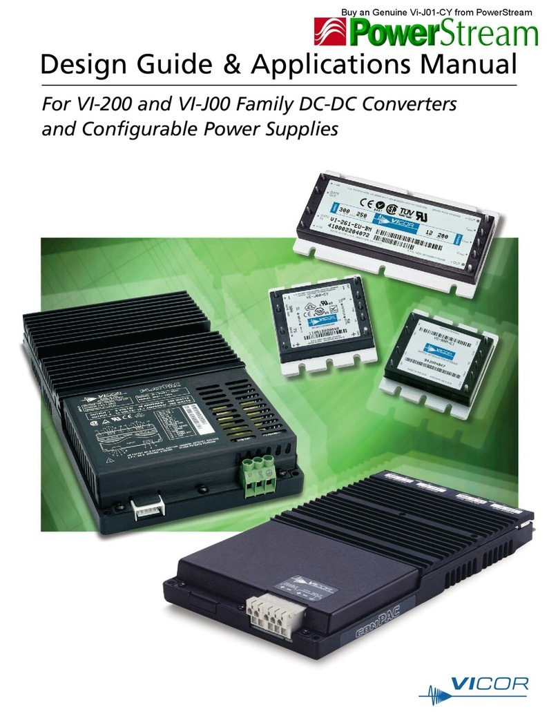
VICOR Maxi Guide

Design Guide & Applications Manual
Maxi, Mini, Micro Family DC-DC Converters and Configurable Power Supplies
Maxi, Mini, Micro Design Guide Rev 5.0
Page 3 of 87 03/2018
1. High-Density DC-DC Converter Technology
AC-DC Products DC-DC Products
Universal
85 – 264VAC
Autoranging
90 – 132VAC
180 – 264VAC
Autoranging
90 – 132VAC
180 – 264VAC
Autoranging
115 – 230VAC
Input
Nominal Input
18 – 425VDC
28VDC, 48VDC,
270VDC
24VDC, 28VDC,
48VDC
Harmonic Attenuator Module
Unity Power Factor
Up to 675W
per module
Filter / Autoranging Rectifier Module
Up to 1,000W
Autoranging Rectifier Module
Up to 1,500W
Front-end System
for EN Compliance
Up to 550W
Transient Protection,
Inrush Current Limiting EMI Filter
Up to 25A
Active EMI Filter
Up to 576W @ 48V
DC-DC Converter
Up to 600W per module
1 – 54Vdc
MINIHAM
FARM3
QPI
DC-DC Converter
Up to 300W per module
1 – 48VDC
DC-DC Converter
Up to 150W per module
1 – 48VDC
Single wire paralleling for
high power, fault tolerant arrays.
Output Ripple Attenuation Module
combines active and passive filtering.
QPO provides active filtering to
achieve differential noise attenuation.
QPO
DC-DC Products
High Boost
HAM
The Maxi, Mini, Micro Family of DC-DC converters are an integral
part of the company’s overall component power solution
strategy (Figure 1.1), which includes advanced factory and design
automation. The modules are available in an unlimited variety of
standard versions, to the extent that the line between custom and
standard DC-DC converter bricks becomes almost indistinguishable.
The design of the control, magnetic, switching and packaging
elements of the module resulted in a component with a power
density of up to 120W/in3(7,3W/cm3) in three package sizes:
Maxi 4.6 x 2.2 x 0.5in [117 x 55,9 x 12,7mm]
Mini 2.28 x 2.2 x 0.5in [57,9 x 55,9 x 12,7mm]
Micro 2.28 x 1.45 x 0.5in [57,9 x 36,8 x 12,7mm]
The modules have one-third the number of parts of
their predecessors.
While the natural by-products of this reduction in parts count has
improved reliability and lower cost. The extra space also means that
the bulk of the converter can now be devoted almost exclusively to
the power train (i.e., the magnetic and switching elements at the
core of the design).
Resistors can be used to trim the output voltage up or down, if
necessary. Six pin styles, three baseplate options and a variety of
data collection and reporting options are available. The devices
have an operating temperature range of –55 to 100°C and come in
five product grades – E, C, T, H and M.
Other specifications include a typical no-load to full-load regulation
of ±0.5%, a programmable output of 10 – 110%, conversion
efficiencies of up to 92% depending on the voltage combination
and power level chosen, and an input-to-output isolation test
voltage of 3,000VRMS [4,242VDC]. All models are parallelable with
N+M fault tolerance and current sharing. Paralleling architectures
feature DC- or AC-coupled interface.
Figure 1.1 — Component power solutions with the Maxi, Mini, Micro Family

Design Guide & Applications Manual
Maxi, Mini, Micro Family DC-DC Converters and Configurable Power Supplies
Maxi, Mini, Micro Design Guide Rev 5.0
Page 4 of 87 03/2018
1. High-Density DC-DC Converter Technology
Key to the design of Maxi, Mini, Micro converters is its high level
of component-level integration. (Figure 1.2) With the aid of hybrid
technology, the device packs all control functions and active
circuitry into two (primary and secondary side) ICs occupying a total
volume of less than 1/10in3[1,6cm3] each.
With Maxi, Mini, Micro devices, the plated-cavity transformer
cores use copper armor, plated onto the ferrite core, to more
closely confine the magnetic flux to couple widely separated
primary and secondary windings. The wider separation provides
greater isolation and therefore lowers input-to-output parasitic
capacitance and noise. The plated cavity also serves to conduct
heat away from the transformer to the baseplate, thus increasing
the power-handling capability of the powertrain and minimizing
temperature rise.
The powertrain assembly is contained between the baseplate and a
terminal-block assembly, with input and output pins recessed. This
allows the converter body to be mounted into an aperture in the
PCB to reduce the height above board. The modules may be wave
soldered or plugged into through-hole or surface-mount sockets.
The Maxi, Mini, Micro devices use a proprietary, low-noise,
integrated power device that has an order of magnitude lower
parasitic effect.
The advances made in the overall design of the Maxi, Mini, Micro
Family DC-DC converters have been complemented by equally
significant advances in the technology used to manufacture
them. Vicor invested in a custom, fully-automated assembly
line specifically designed for the assembly of Maxi, Mini, Micro
power components. To further augment its Maxi, Mini, Micro
product offering, Vicor has created an online user-interface tool,
PowerBenchTM, that allows customers to specify DC-DC module
requirements anytime, anywhere via the internet.
Bottom View
• Standard MLP power devices
• Efficient pick-and-place assembly
Top View
• Surface-mount components for greater
manufacturing efficiency
• Standard reflow process
Baseplate
• Simplified baseplate construction
Complete Assembly
• Insert molded terminal block for more
accurate pin positioning
• One-piece cover with label
• Encapsulated for superior thermal performance
Figure 1.2 — Maxi assembly shows high level of integration
Model Number
Serial No. & Date Code

Design Guide & Applications Manual
Maxi, Mini, Micro Family DC-DC Converters and Configurable Power Supplies
Maxi, Mini, Micro Design Guide Rev 5.0
Page 5 of 87 03/2018
1. High-Density DC-DC Converter Technology
+OUT
+SENSE*
SC
–OUT
–SENSE*
+IN
PC
PR
–IN
Primary Control IC Secondary Control IC
The Maxi, Mini, Micro’s ZCS / ZVS power-processing architecture
(Figure 1.3) enables efficient, low-noise, high-frequency operation.
The main switch is common drain for improved thermal and noise
management. The reset switch located within the primary control
IC is common source for ease of control.
The control circuitry is integrated into two (primary- and
secondary-side) ICs. The result is a significant reduction in parts
with the ensuing savings in cost and increase in reliability. This
integration also provides extra room for the power train.
Maxi, Mini, Micro transformers place the primary and secondary
windings far apart, but contain the magnetic flux using a copper
armor plated onto the ferrite core. The armor also conducts excess
heat to the baseplate.
Figure 1.3 — Maxi, Mini, Micro: Basic powertrain and control (*Not included in Micro family)
This manual suits for next models
2
Table of contents
Other VICOR Media Converter manuals
Popular Media Converter manuals by other brands

Moxa Technologies
Moxa Technologies NPort 5600-8-DT Quick installation guide

Omega Digitech
Omega Digitech M202 user manual

Hengstler
Hengstler AC 58 SUCOnet installation instructions

TR-Electronic
TR-Electronic QDH Series user manual

Moxa Technologies
Moxa Technologies VPort 364 Series user manual

iNels
iNels RFSG-1M quick start guide