VICOR VI Chip VTM User manual

UG:014 vicorpower.com Applications Engineering: 800 927.9474 Page 1
Introduction
This evaluation board oers a convenient means to evaluate the performance of
Vicor’s VTM® current multiplier. All evaluation boards include sockets for easy "plug
and play" insertion and removal of through-hole components and wires. The board
provides lugs for power connections, connectors for easy PRM-VTM evaluation board
interconnects, and kelvin voltage measurement test points of all pins of the VTM.
Please refer to the appropriate VTM datasheet for performance and operating limits,
available for downloading at www.vicorpower.com.
IMPORTANT NOTICE:
Please read this document before setting up a VTM evaluation board
This user guide is not comprehensive and the operator should not substitute it for
common sense and good practice. The following procedures should be followed
during operation:
nWear approved safety glasses when testing electronic product.
nProvide strain relief for wires and secure the board on the test bench to avoid
displacement.
nRemove the power and use caution when connecting and disconnecting all test
probes and interface lines to avoid unintentional short circuits and contact
with hot surfaces.
nNever attempt to disconnect the evaluation board from a PRM® evaluation board
while power is applied. This system is not designed to demonstrate the
hot plug capability.
VI Chip®VTM®
Evaluation Board
USER GUIDE | UG:014
Written by: Ankur Patel
Applications Engineer
August 2013
Contents Page
Introduction 1
Contents 2
Features 2
Board Description 3
General Components 4
Test Points & Sockets 5
Schematic 7
Assembly Drawings 9
Bill of Materials 10
VTM Evaluation Boards 12
Standalone Operation 12
vs PRM-VTM
PRM-VTM Non-Isolated 12
Remote Sense
Paralleling 13
Push Pin Heat Sink 13
Installation
Part Ordering Information 13

UG:014 vicorpower.com Applications Engineering: 800 927.9474 Page 2
Contents
All VTM® evaluation boards arrive with the following contents.
(The user guide can be downloaded from the www.vicorpower.com.)
n 1 x VTM Evaluation board
n 1 x VI Chip push pin heat sink
n 2 x VI Chip push pins for heat sink installation
n 1 x Hardware kit
n 2 x Through hole mating connectors
n 1 x Through hole 22 µF input capacitor
Features
1. Input filtering – ceramic capacitors and sockets for installation of throughhole
aluminum electrolytic capacitor
2. Output filtering – ceramic capacitors
3. Oscilloscope probe jack for output voltage signal measurement
4. Kelvin test points for measurement of input voltage, output voltage and all signal
pins of the VTM
5. Sockets for each test points for easy installation of through-hole components and
solid wires to facilitate wiring to external circuitry and test equipment
6. Input and output lugs for power supply and load connections
7. Input power and signal connectors for testing with PRM module
8. Provisions for non-isolated remote sense operation with PRM evaluation board
a. Provision to inject network analyzer signals
b. 2512 resistor footprint for installation of zero ohm resistor to break the VTM
isolation for non isolated remote sense operation
c. Sense pins with local Sense Resistors to +OUT and –OUT

UG:014 vicorpower.com Applications Engineering: 800 927.9474 Page 3
Board Description
The following section provides a detailed description of the evaluation board
components, test points and sockets.
Figure 1.
Board Description
9
10
7
8
5
6
3
4
1
2
-OUT
-OUT
VC
VC
-OUT
-OUT
+OUT
+OUT
+OUT
+OUT
9
10
7
8
5
6
3
4
1
2
-S
+S
V_TM
V_PC
VTM_-IN
V_IM
J11
Signal connector
J14
Power/signal connector
Figure 2.
Power/signal connectors
pinout, front view

UG:014 vicorpower.com Applications Engineering: 800 927.9474 Page 4
General Components
1. VTM® (PS10)
2. Input lugs (+IN and –IN): Sized for #10 hardware. Use these for making connection
to the input source. This board does not contain reverse polarity protection. Check
for proper polarity before applying power.
3. Input filtering: Input capacitor (CIN) and filtering (ceramic capacitors) allows for
stable operation with most input sources. Sockets can be used for easy installation
of aluminum-electrolytic input capacitor.
4. Power/Signal connector (J14): Used to receive the power (+OUT/-OUT) and VC from
upstream PRM board when used.
5. Signal connector (J11): Used to transfer VTM PC, IM, TM, -IN and output sense
signals between the VTM and PRM® boards. TM pin of the VTM provides feedback
to the VT pin of the PRM in adaptive loop operation of PRM and VTM. +S and –S
signals provide voltage sensing to the PRM remote sense circuitry for non-isolated
remote sense operation.
6. Output lugs (+OUT, -OUT): Sized for #10 hardware. Use these lugs to connect the
output directly to the load.
7. Output filtering(ceramic capacitors): Helps to minimize switching ripple
of the output voltage.
8. Output oscilloscope probe jack (J12): Used for making accurate scope
measurements of the output voltage (i.e. ripple). Remove scope grounding lead
and insert probe directly into jack ensuring a good connection between the jack
and the probe ground barrel. Do not attempt to install while power is applied. May
not be compatible with all scope probes.
9. TM filtering: Filters the TM signal noise. Corner frequency of the filter is set well
below the VTM switching frequency.
10. Sense pins and local sense resistors: Used to sense the output votage of the VTM
for non-isolated remote sense operation. Local sense resistors can be bypassed by
connecting twisted pair from the sense test points directly to the load.
11. VTM isolation boundry: Zero ohm shunt can be soldered or use sockets to break the
isolation for non isolated remote sense operation of VTM board and PRM board.
12. Heat sink push-pins: Secure the heat sink to the board using these pins. Use of a fan
across the heat sink is highly recommended for proper cooling.
13. Mating connectors: Connect the PRM and VTM with the connecters to share power
and signal connection.

UG:014 vicorpower.com Applications Engineering: 800 927.9474 Page 5
Test Points and Sockets Description
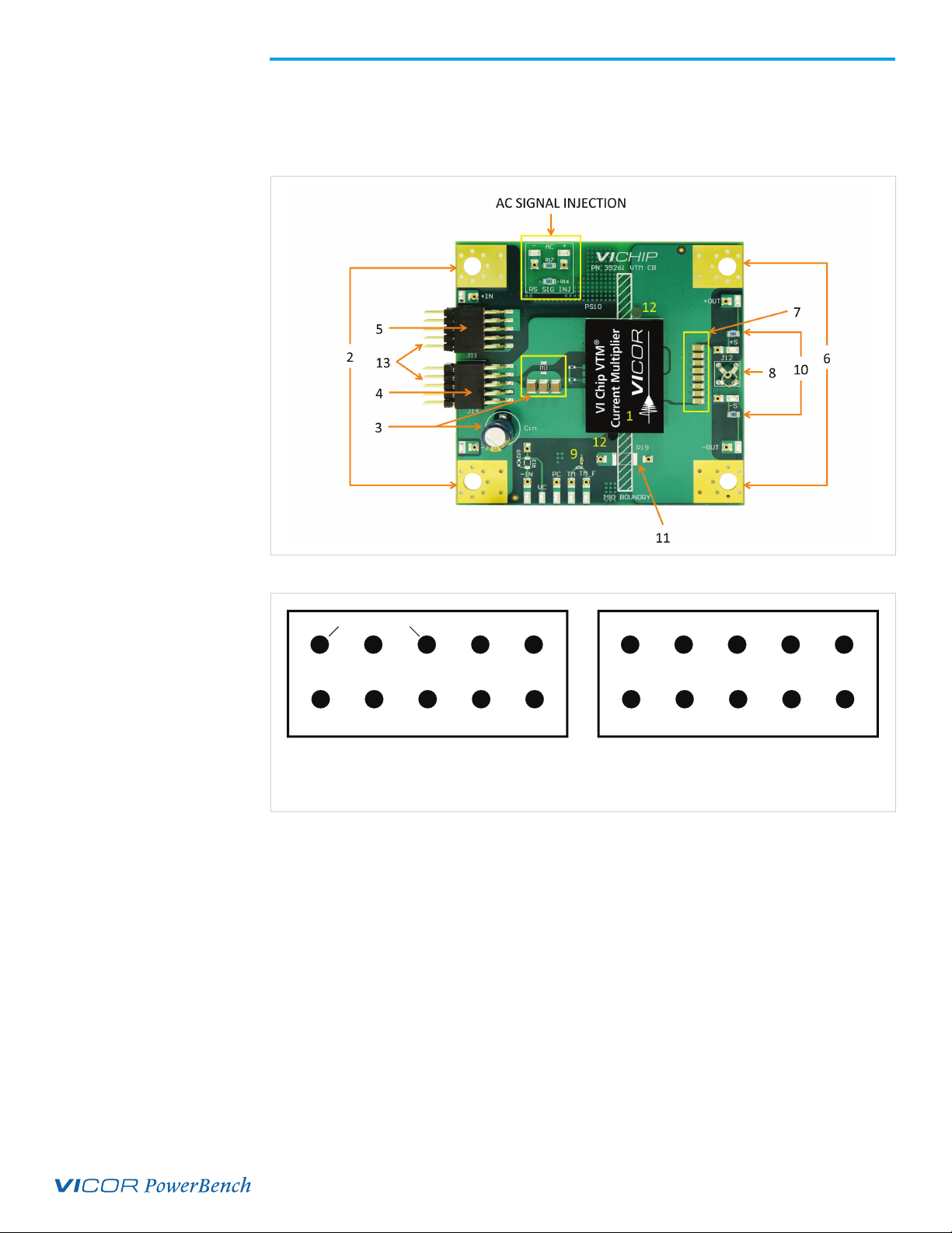
Each test point socket accepts 0.015 – 0.025 inch diameter leads of solid wires and
through-hole components for use with external circuitry and test equipment. All test
points are aligned on the board’s edge for easy access, measurement and external
circuitry connections. Each point is labeled and is accompanied by an additional
adjacent socket.
Reference
Designator
Functional
Name
Functional
Description
TP20,
TP21
+IN,
–IN
Input voltage test points provide kelvin connection to input pins of the
VTM®. Use these test points for measuring the input voltage of the VTM
to avoid error due to interconnect losses.
H20,
H21
+IN,
–IN
Sockets for +IN and –IN test points. Kelvin connected to the VTM input
pins.
TP17,
TP22
+OUT,
–OUT
Output voltage test points provide kelvin connection to output pins of the
VTM. Use these test points for measuring the output voltage of the VTM
to avoid error due to interconnect losses.
H17,
H22
+OUT,
–OUT
Sockets for +OUT and –OUT test points. Kelvin connected to the VTM
output pins.
TP12 VC
VC test point provides kelvin connection to VC pin of the VTM. Can be
used to apply and measure the VC signal with reference to –IN signal. VC
is used to enable the VTM. Apply 14 V to VC to enable the VTM, when
not using PRM.
H12 VC Socket for VC test point. Kelvin connected to VC pin of the VTM. Aligned
with –IN socket for placing through hole resistor from VC to –IN.
TP10 PC
PC test point provides kelvin connection to PC pin of the VTM. Can be
used to measure the PC signal with reference to –IN signal. PC can be
used to disable the VTM in the presence of input power. Connecting PC
to –IN will disable the VTM.
H10 PC Socket for PC test point. Kelvin connected to PC pin of the VTM.
TP11 TM TM test point provides kelvin connection to TM pin of the VTM. Can be
used to measure and monitor the TM signal with reference to –IN signal.
H11 TM Socket for TM test point. Kelvin connected to TM signal of the VTM
TP16 FILTERED
TM
Provides the low noise measurement of TM signal.Output of the TM RC
filter can be measured using this testpoint with reference to –IN.
H15 FILTERED
TM Socket for TP16 test point.
TP13 –IN -IN test point provides kelvin connection to –IN pin of the VTM. All signals
on input side of the VTM are measured with reference to –IN signal of the VTM.
H13 –IN Socket for –IN test point.
TP15,
TP14
+S,
–S
Output sense test points provide connection to the output pins of
VTM through local sense resistors. Routed to connector J11 for use
in differential non isolated remote sense circuitry for Remote Sense
operation of VTM and PRM®.
Table 1.
Test points and
sockets description

UG:014 vicorpower.com Applications Engineering: 800 927.9474 Page 6
Reference
Designator
Functional
Name
Functional
Name
H15,
H14
+S,
–S Sockets for +S and –S test points.
TP18,
TP19 AC SIG INJ
Can be used to inject the isolated signal of network analyzer for bode
plot measurement to measure the stability in Remote Sense operation
using VTM and PRM
H18,
H19 AC SIG INJ Sockets for AC +/- test points.
TP30 IM
IM test point provides the kelvin connection to IM pin. Can be used to
measure the IM signal of the half VTM. IM can be used to monitor the
output current of the VTM. Available on half VTM boards only.
H27 IM Socket for IM test point.
Test Points and Sockets Description (Cont.)

UG:014 vicorpower.com Applications Engineering: 800 927.9474 Page 7
Schematics
Figure 3a.
Schematic - Full Chip VTM
evaluation board
1206
C12
1206
C16
1206
C13
1206
C17
1206
C14
1206
C18
1206
C15
1206
C19
TP11TP10
TP20
TP17
TP22
TP21
TP12
1210
C21
1210
C22
1210
C20
1206
R16
1206
R15
1206
R13
J13
J10
J16
TP24
TP25
TP26
J12
VC
TM
PC
PC TM VC
-IN
H12
H13
PC
TM
+OUT
-OUT
-IN
+OUT
-OUT
H23
H24
VC
H11
H10
CIN
1206
R18
TP14 TP15
-SENSE +SENSE
1206
R17
0603
R11
0603
R10
H18 H19
TP19TP18
0603
R14
0603
C11
TMTM_F
-IN
1206
R12
0603
C10
TP16 H14 H15
NO GND
HS10
TP13
H16
+IN
-IN
+OUT
-OUT
TM
VTM
VC
PC
PRIMARY SECONDARY
ISOLATION BOUNDRY
PS10
VTM_OFF_BD_VIBRICK
2512
R19
H25 H26
1 2
3 4
5 6
7 8
9 10
J11
1 2
3 4
5 6
7 8
9 10
J14
FIDUCIAL
FID01
FIDUCIAL
FID02
H21
H20
H22
H17
KELVIN WITH DIFFERENTIAL ROUTING
KELVIN
TP29
TP27
TP23
TP28
J15
-IN
KELVIN -IN
KELVIN -IN

UG:014 vicorpower.com Applications Engineering: 800 927.9474 Page 8
Schematics (Cont.)
Figure 3b.
Schematic - Half Chip VTM
evaluation board
1206
C12
1206
C16
1206
C13
1206
C17
1206
C14
1206
C18
1206
C15
1206
C19
TP11TP10
TP20
TP17
TP22
TP21
TP12
1210
C21
1210
C22
1210
C20
1206
R16
1206
R15
1206
R13
J13
J10
J16
TP24
TP25
TP26
J12
VC
TM
PC
PC TM VC
-IN
H12
H13
TM
+OUT
-OUT
-IN
+OUT
-OUT
H23
H24
VC
H11
H10
CIN
1206
R18
TP14 TP15
-SENSE +SENSE
1206
R17
0603
R11
0603
R10
H18 H19
TP19TP18
0603
R14
0603
C11
TMTM_F
-IN
1206
R12
0603
C10
TP16 H14 H15
NO GND
HS10
TP13
H16
2512
R19
H25 H26
1 2
3 4
5 6
7 8
9 10
J14
FIDUCIAL
FID01
FIDUCIAL
FID02
H21
H20
H22
H17
KELVIN WITH DIFFERENTIAL ROUTING
KELVIN
TP29
TP27
TP23
TP28
J15
-IN
KELVIN -IN
KELVIN -IN
IM
TP30
IM
H27
0603
R20
1 2
3 4
5 6
7 8
9 10
J11
TP31
+IN
-IN
+OUT
-OUT
TM
HALF VTM
VC
PC
PRIMARY SECONDARY
ISOLATION BOUNDRY
IM
PS10
IM
PC

UG:014 vicorpower.com Applications Engineering: 800 927.9474 Page 9
Assembly Drawings
Figure 4a.
Assembly drawing – Top view:
Full Chip VTM evaluation board
Figure 4b.
Assembly drawing – Top view:
Half Chip VTM evaluation board
PF15
TP22
H26H25
H24 H23
H22
H21
H20
H19
H18
H17
H16
H15
H14
H13
H12
H11
H10
TP21 TP20
TP19TP18
TP17
TP16
TP15
TP14
TP13
TP12
TP11
TP10
PS10 J12
HS10
R19
R18
R17
R16
R15
R14
R13
R12
R11
R10
J14
J11
C22
C21
C20
C19
C18
C17
C16
C15
C14
C13
C12
C11
C10
FID02
FID01
J10J13
J15 J16
PF15
TP22
H26H25
H24 H23
H22
H21
H20
H19
H18
H17
H16
H15
H14
H13
H12
H11
H10
TP21 TP20
TP19TP18
TP17
TP16
TP15
TP14
TP13
TP12
TP11
TP10
PS10 J12
HS10
R19
R18
R17
R16
R15
R14
R13
R12
R11
R10
J14
J11
C22
C21
C20
C19
C18
C17
C16
C15
C14
C13
C12
C11
C10
FID02
FID01
J10J13
J15 J16
R20
TP30
H27
PF18

UG:014 vicorpower.com Applications Engineering: 800 927.9474 Page 10
Bill of Materials
Following table describes the common components of all VTM evaluation boards.
Reference
Designator Description Manufacturer Manufacturer
Part Number
C10 NOT APPLIED
C11 CAP X7R .1uF 10%
100 V 0603
Murata
Manufacturing GRM188R72A104KA35D
C12 - C19 Design Specific – See table 3
C20 - C22 CAP X7R 2.2uF 10%
100 V 1210 .102 MAX HT
TDK CORP OF
AMERICA C3225X7R2A225KT5LOU
CIN_PUT_IN_BOX CAP ALEL 22uF 20%
100 V RADIAL 8 X 11.5 Panasonic EEUFC2A220
H10 - H27 PIN RECPT .015/.025 DIA
0667 SER TH Mill-Max 0667-0-57-15-30-27-1
HEADER_IN_BOX CONN 10POS HEADER STR
M-M 3A/ 0.100 Sullins PEC05DABN
J11, J14 CONN 10 PINS 2.54MM PITCH
DUAL ROW SM HO
Global Connector
Technology BG225-10-A-N-A
J12 JACK VERTICAL MECH
THRU HOLE Tektronix 131-5031-00
PCB Design Specific – See table 3
PS10 Design Specific – See table 3
R10 NOT APPLIED
R11 NOT APPLIED
R12 NOT APPLIED
R13, R15 RES 10 OHM 1/4W 1% 1206 KOA Speer
Electronics RK73H2BTTD10R0F
R14 RES 1K OHM 1/10W 1% 0603 KOA Speer
Electronics RK73H1JTTD1001F
R16, R17 RES 20 OHM 1/4W 1% 1206 KOA Speer
Electronics RK73H2BTTD20R0F
R18 RES 10m OHM 1/4W 1% 1206 Vishay WSL1206R0100FEA
R19 NOT APPLIED
TP10-TP22, TP30 TEST POINT, SURFACE MOUNT Keystone
Electronics 5017
Table 2.
Common components

UG:014 vicorpower.com Applications Engineering: 800 927.9474 Page 11
Bill of Materials (Cont.)
Following table describes the design specific components of all VTM® evaluation boards.
Reference
Designator Description Manufacturer Manufacturer
Part Number Evaluation Board
C12 - C19 CAP X5R 47uF
20% 6.3 V 1206
Murata
Manufacturing GRM31CR60J476ME19K K = 1/12, 1/16,
1/24, 1/32 VTMs
C12 - C19 CAP X5R 10uF
10% 25 V 1206
Murata
Manufacturing GRM31CR61E106KA12L K = 1/3, 1/4, 1/5,
1/6, 1/8 VTMs
C12 - C19 CAP X7R 1.0uF
10% 100 V 1206
Murata
Manufacturing GRM31CR72A105KA01L K = 1, 2/3, 1/2,
VTMs
PCB SNGLTD PCB FULL
CHIP VTM CB Vicor 39261 Full Chip VTM
boards
PCB SNGLTD PCB HALF
CHIP VTM CB Vicor 39262 Half Chip VTM
boards
PS10 Full Chip / Half Chip VTM, Part Number refer to datasheet
Table 3.
Design specific components

UG:014 vicorpower.com Applications Engineering: 800 927.9474 Page 12
PRM®& VTM®Evaluation Boards
The VTM evaluation board has been designed for compatibility with all PRM evaluation
boards to accommodate any PRM-VTM combination. The VTM evaluation board contains
dual connectors designed to mate with J10 and J13 on PRM board. An additional signal
connector shares VTM signal pins along with TM, S+ and S- to the PRM board. When
connected to a PRM evaluation board the TM signal provides feedback to the VT pin of
the PRM enabling temperature compensation in Adaptive Loop configuration.
Standalone Operation vs PRM-VTM Operation
In standalone VTM operation, the VTM cannot self-start with only an input voltage
applied. A voltage of 14 V must be applied to its VC pin or test point for it to become
active. Ensure that the applied VC slew rate is within the specified limits of the device.
The VC voltage may be removed once the VTM has started and the input voltage has
reached 26 V or VC can be applied continuously to allow operation down below 26 V
input voltage. When connected together, the PRM provides power and the VC pulse via
the J14 connector to the VTM. A 22 uF,100 V electrolytic input capacitor is provided with
the board and is recommended in standalone VTM operation.
Refer to the VI Chip PRM evaluation board UG:013 for more information on various
modes of PRM+VTM operation.
PRM-VTM Non-Isolated Remote Sense
To demonstrate non-isolated remote sense with a PRM evaluation board, the VTM
isolation must be broken by tying VTM -IN to –OUT. This can be done using sockets on
both side of R19 resistor footprint or by soldering a 2512 zero ohm resistor at the R19
location. Output sense test points are routed to connector J11 and provide feedback to the
PRM remote sense circuitry. By default, the +S and –S pins are connected to the output
pins of VTM through local sense resistors. To demonstrate sensing at a remote point of
load, the local sense resistors can be bypassed by connecting the +S and –S test points to
the desired sense location. Use a twisted pair to avoid noise pickup.
It is recommended to use a network analyzer to measure the closed loop frequency
response when adjusting compensation. The VTM boards provide test points which can
be used to inject the network analyzer AC signal and measure the closed loop response.
For PRM-VTM Remote Sense mode, test points are provided on the VTM board in series
with the +S connections (Labeled “RS Sig Inj +/-“) and should be used.
Figure 5.
PRM evaluation board
connection to
VTM evaluation board

UG:014 vicorpower.com Applications Engineering: 800 927.9474 Page 13
Paralleling
The paralleling and current sharing capability of the devices can be demonstrated by
stacking multiple evaluation boards and interconnecting the inputs and outputs with
standos of sucient current rating to create a parallel array. When paralleling VTMs,
in standalone VTM® operation, VC pins should be connected together to enable the
synchronized startup.
PRM® boards can also be connected in parallel to create high power PRM-VTM arrays.
PRM input, outputs and interconnect signals need to be connected in parallel using
same size standos. Each VTM requires a VC signal from a PRM in order to start and it is
recommended to connect one PRM VC to one VTM VC using the connector J13 on PRM
board and J14 on VTM board when possible. If needed a single PRM VC can be used to
drive up to two VTMs (will require additional o board connections).
Push Pin Heat Sink Installation
Each VTM demonstration board comes with its own heat sink and push pins for
installation. Before testing, it is highly recommended that the heat sink be installed in
the appropriate location for each board. When installing the push pin heat sink, use
caution not to exceed the maximum compression on the device listed in the data sheet.
For most lab environments a fan blowing across the evaluation board is recommended.
Using the VTM Evaluation Board for Reverse Operation
VTMs are capable of bidirectional power transfer between the Primary and
Secondary power terminals. Certain VTMs such as the VTM48EF040T050B0R, and
VTM48EF120T025A0R are qualified for continuous operation in reverse (power transfer
from Secondary to Primary).
Reversible VTMs are usually designated with an R as the last character of the part
number, however, refer to the datasheet to determine if a particular VTM is qualified for
continuous reverse operation.
Reverse operation with a PRM-VTM configuration is beyond the scope of this document.
In standalone operation, the applied VC voltage must be referenced to -PRI(-IN). VC
can be applied before or aer the secondary (source) voltage. Applying VC aer the
secondary voltage will result in a non-negligible amount secondary inrush current as
described in the datasheet. Refer to the datasheet for the peak secondary inrush value
and ensure the source is rated appropriately. Fusing for the evaluation board is located
on the primary side. If fusing on the secondary (source) side is required, then it should
be added externally based on the device ratings.
In order to test a qualified VTM in the reverse direction, follow the the procedure for
VTM standalone operation and make the following changes:
1. Connect the voltage source to the Secondary (Output) lugs.
2. Connect the load to the Primary (Input) lugs.
Ensure the applied source voltage has the correct polarity and is within the Secondary
Voltage ratings of the VTM. It may be necessary to install an input capacitor across the
Secondary terminals to decouple the input source.

The Power Behind Performance
Rev 1.2 11/14 vicorpower.com Applications Engineering: 800 927.9474 Page 14
Part Ordering Information
The VTM evaluation boards can be ordered from the Vicor website:
www.vicorpower.com. To order the demo boards, substitute VTM with VTD
in VTM part number.
See http://www.vicorpower.com/cms/home/products/vi-chip/vichip_VTM_current_
multiplier for part number listing.
Other manuals for VI Chip VTM
1
Table of contents
Other VICOR Motherboard manuals

VICOR
VICOR VI Chip BCM User manual

VICOR
VICOR PI3741-0x-EVAL1 User manual

VICOR
VICOR VI Chip High-Voltage BCM User manual

VICOR
VICOR PI352 series User manual

VICOR
VICOR VITA62 3U User manual

VICOR
VICOR DCM2322 User manual

VICOR
VICOR VI Chip BCM User manual

VICOR
VICOR PI3740-00-EVAL1 User manual

VICOR
VICOR 4623 User manual

VICOR
VICOR VI Chip VTM User manual
Popular Motherboard manuals by other brands

Asus
Asus A7V133 user guide

Avalue Technology
Avalue Technology ERX-G41 Quick installation guide

ST
ST STEVAL-ISC004V1 user manual

VIA Technologies
VIA Technologies VB8001-16 - VIA Motherboard - Mini ITX user manual

MSI
MSI B550M PRO-VDH WIFI quick start

Connect Tech
Connect Tech BlueStorm/Express RS-232 user manual