DC Inverter Duct Type Unit
7
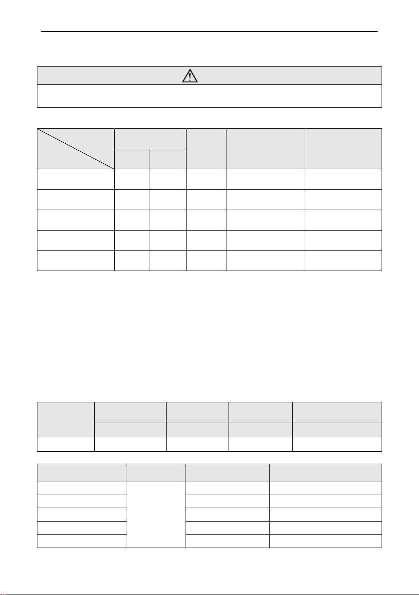
Notes:
①. The fuse is located on the main board.
②. Install the disconnect device with a contact gap of at least 3 mm in all poles
nearby the units (Both indoor unit and outdoor unit).The appliance must be
positioned so that the plug is accessible.
③. The specifications of the breaker and power cable listed in the Table above
are determined based on the maximum power (maximum amps) of the unit.
④. The specifications of the power cable listed in the Table above are applied
to the conduit-guarded multi-wire copper cable (like, YJV copper cable,
consisting of PE insulated wires and a PVC cable jacket) used at 40°С and
resistible to 90°С(see IEC 60364-5-52). If the working condition changes,
they should be modified according to the related national standard.
⑤. The specifications of the breaker listed in the Table above are applied to
the breaker with the working temperature at 40°С. If the working condition
changes, they should be modified according to the related national
standard.
⑥. Take 2 pieces of power cord of 0.75mm2as the communication lines
between indoor and outdoor unit, with their longest lengths of 50m. Please
select the appropriate line length as per the actual installation conditions.
The communication lines can not be twisted together. For the unit (≤30K),
it’s recommended to use 8m long communication line.
⑦. Take 2 pieces of power cord of 0.75mm2as the communication lines
between the wired controller and the indoor unit, with their longest lengths
of 30m. Please select the appropriate line length as per the actual
installation conditions. The communication lines can not be twisted
together. It’s recommended to use 8m long communication line.
⑧. The wire size of the communication line should be no less than 0.75mm2.
It’s recommended to take 0.75mm2power cords as the communication line.
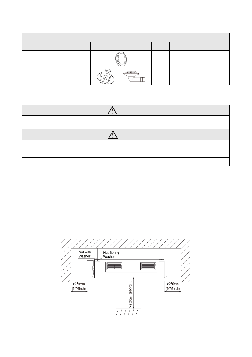
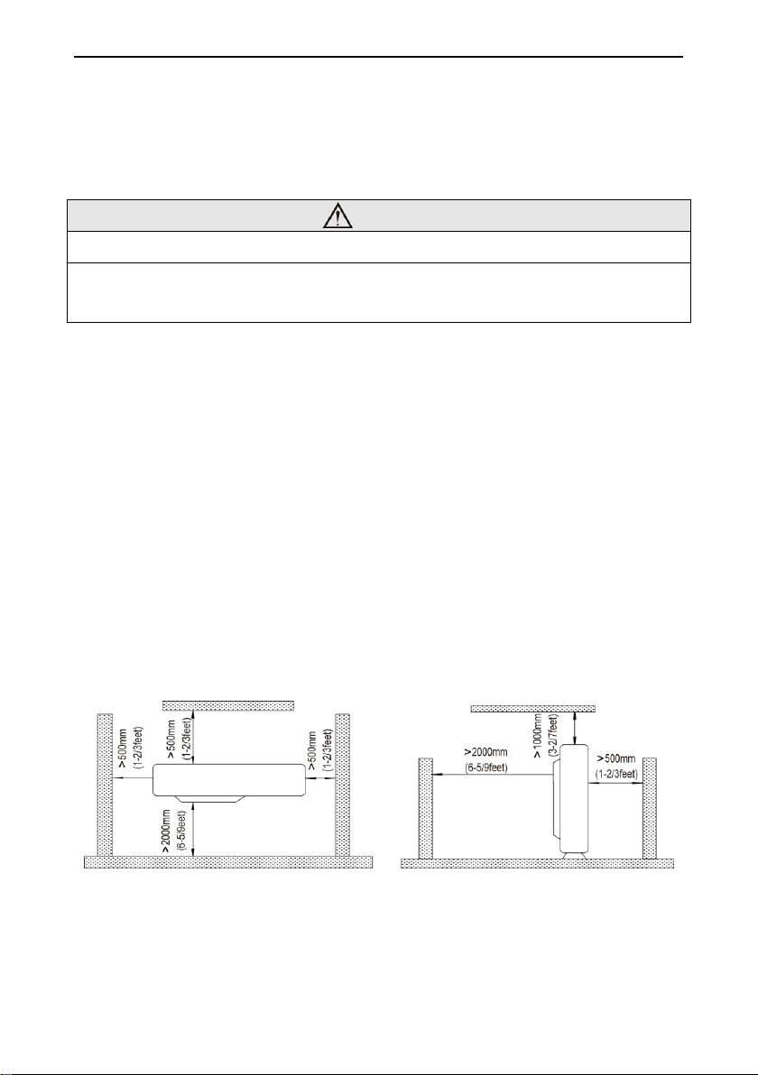
4 Installation of the Unit
4.1 Installation of the Indoor Unit
4.1.1 Indoor unit dimension