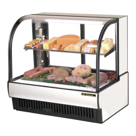
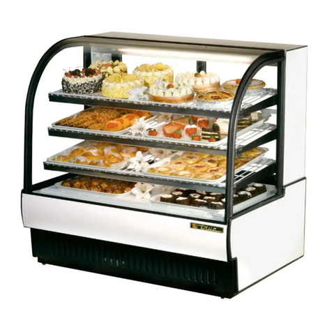
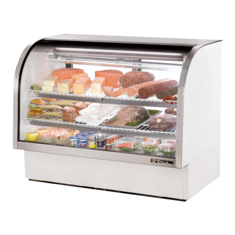
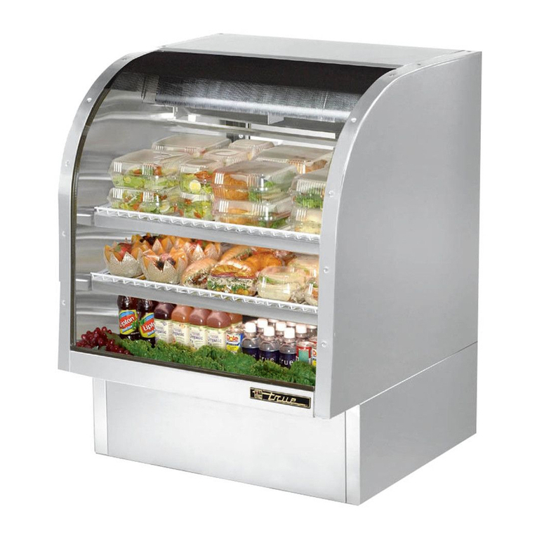
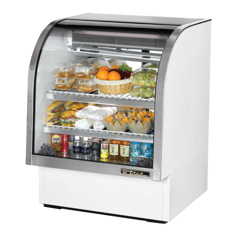
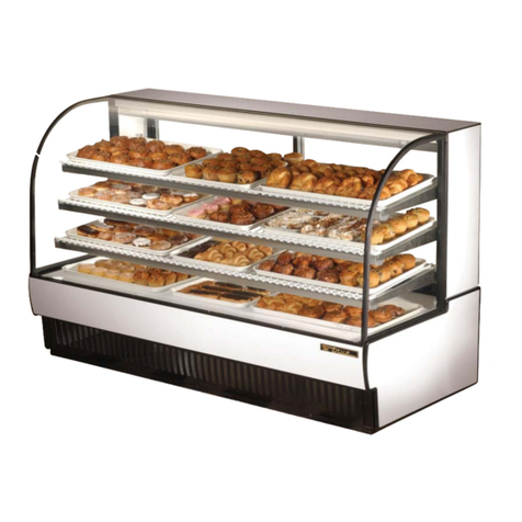
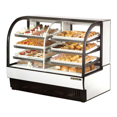
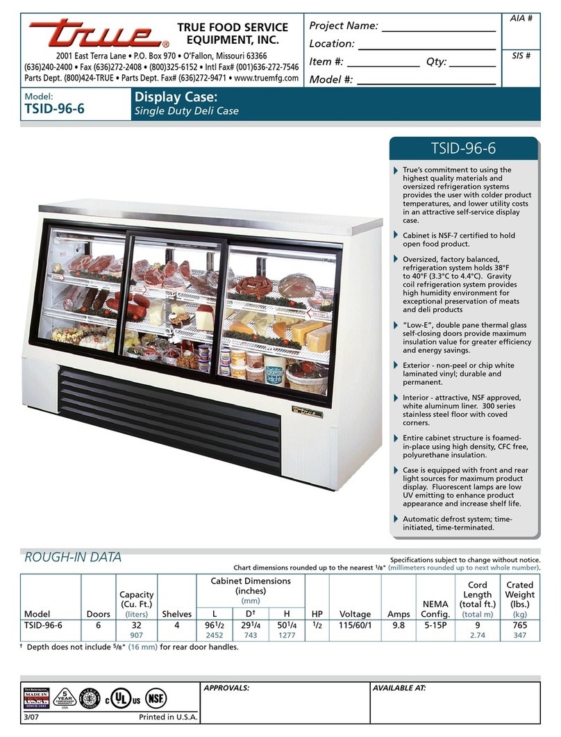
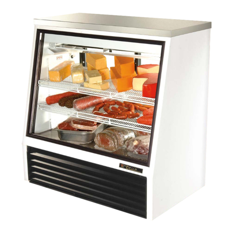
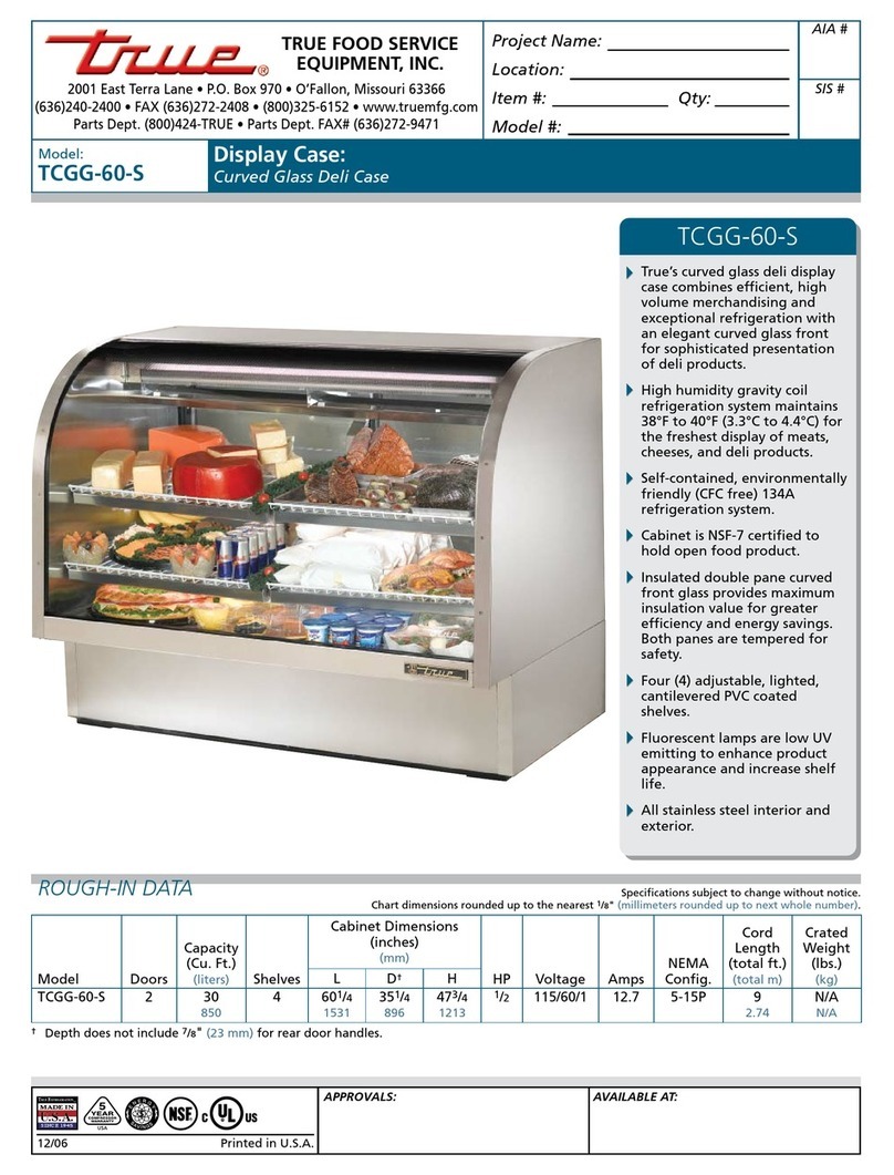
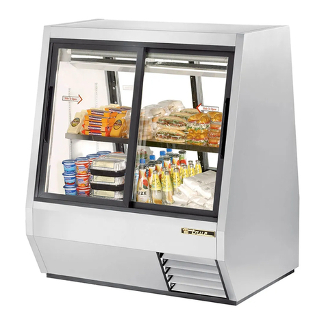
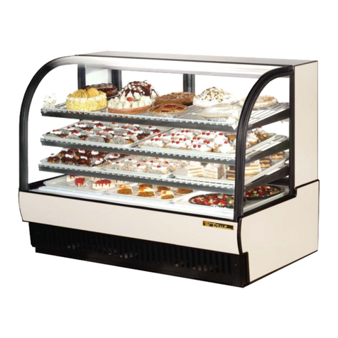
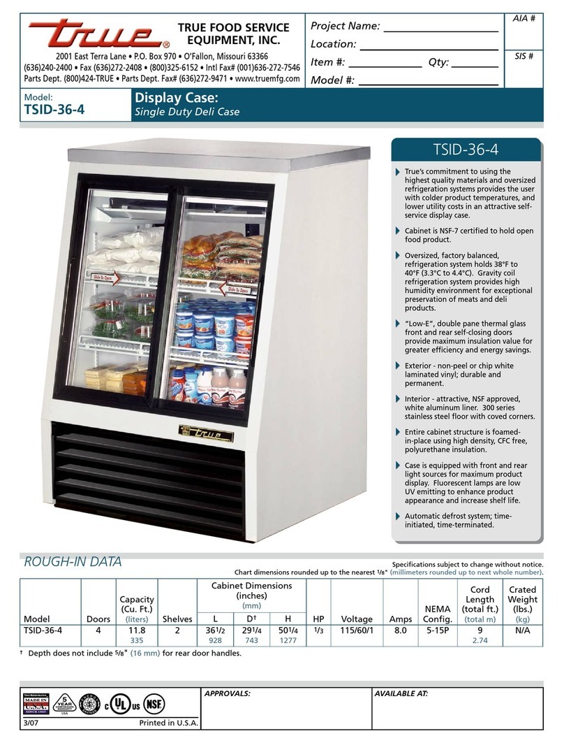
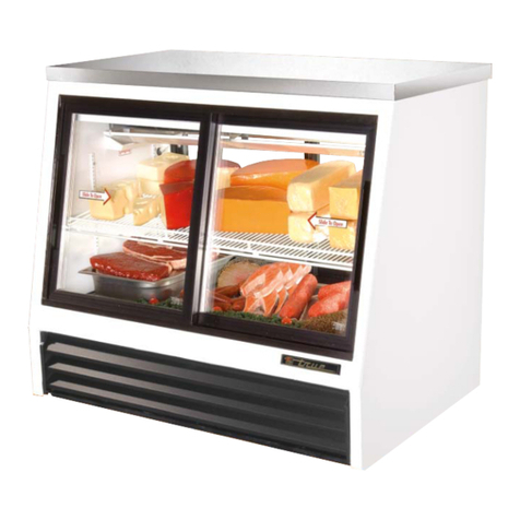
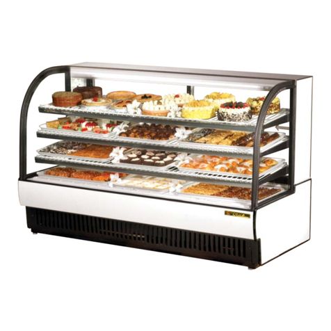
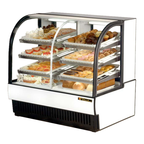
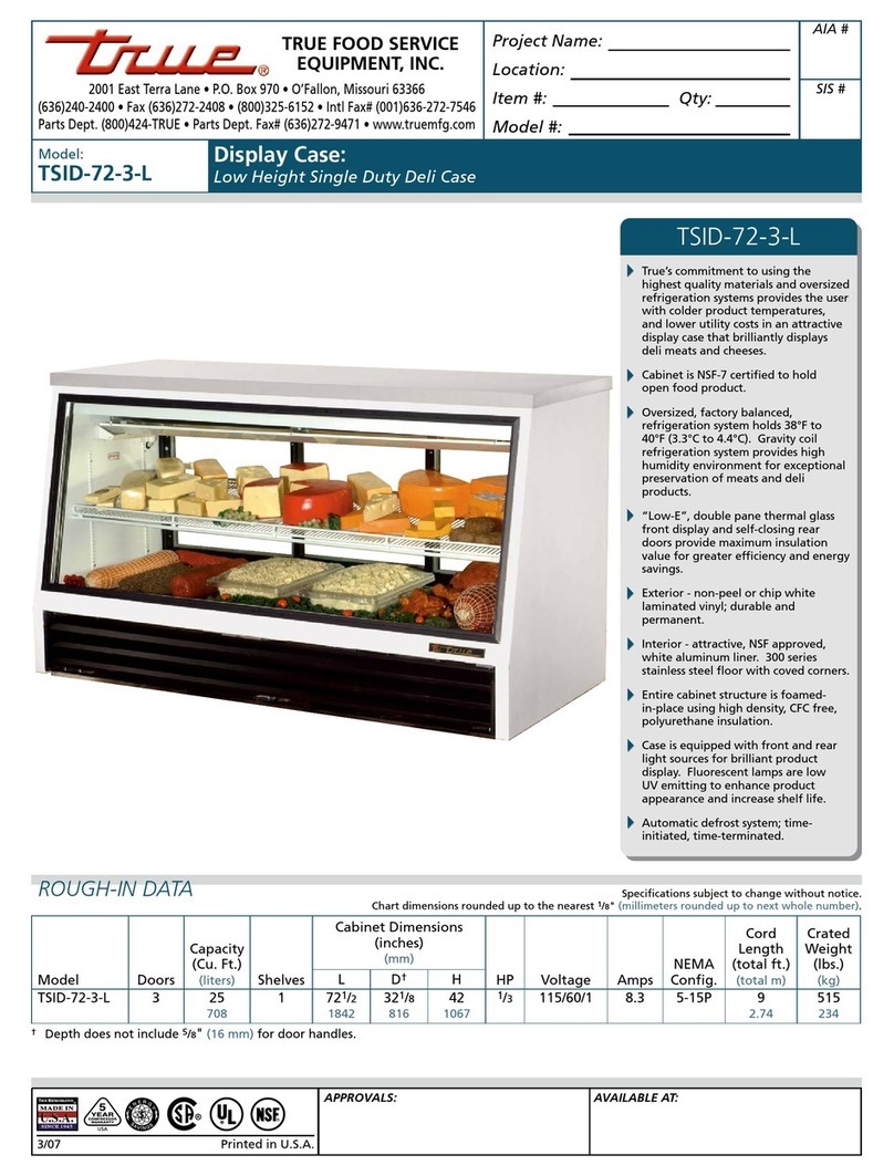
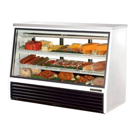
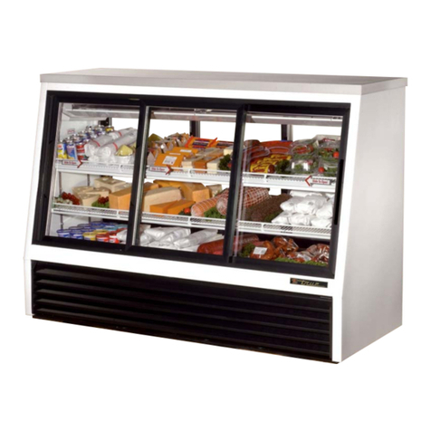
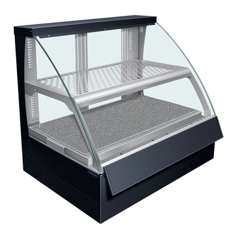
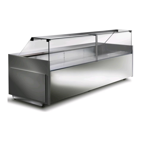
True TCGG-48-S User manual

............ www.truemfg.com ............
INSTALLATION MANUAL FOR TCGG MODELS
(CURVED GLASS DELI CASE)
TCGG MODELS
(CURVED GLASS DELI CASE)
CONGRATULATIONS!
You have just purchased the finest commercial
refrigeration available. You can expect many years
of trouble-free operation.
TRUE FOOD SERVICE EQUIPMENT, INC.
2001 East Terra Lane • O’Fallon, Missouri 63366-4434
(636) 240-2400 • FAX (636) 272-2408 • INT’L FAX (636) 272-7546 • (800) 325-6152
Parts Department (800) 424-TRUE • Parts Department FAX# (636) 272-9471
TABLE OF CONTENTS
Safety Information
Safety Precautions ––––––––––––––––––––––––– 1
Proper Disposal –––––––––––––––––––––––––––– 2
Connecting Electricity ––––––––––––––––––––––– 4
Adapter Plugs ––––––––––––––––––––––––––––– 4
Installation / Operation Instructions
Ownership ––––––––––––––––––––––––––––––– 4
Required Tools –––––––––––––––––––––––––––– 4
Uncrating –––––––––––––––––––––––––––––––– 4
Location –––––––––––––––––––––––––––––––––– 5
Leveling Cabinet ––––––––––––––––––––––––––– 5
Defrost Timer Instructions (Grasslin Timer) –––––––– 6
Conductors and Circuits ––––––––––––––––––––––– 7
Electrical Instructions & Start-up –––––––––––––––– 8
Sealing the Cabinet to the floor –––––––––––––––– 9
Shelving Installation & Operation ––––––––––––– 9-10
Maintenance, Care & Cleaning
Temperature Control Adjustment –––––––––––––– 11
Cleaning Condenser Coil –––––––––––––––––– 12-13
Stainless Steel Equipment Care & Cleaning––––– 14-15
Light Bulb Replacement ––––––––––––––––––––– 15
Warranty (U.S.A. & CANADA ONLY!)–––––––––––––– 16
TCGG-48-S
TCGG-72-S *Spanish, German, French and Dutch versions included.
#912627


............ www.truemfg.com ............
True Food Service Equipment, Inc.
11
• Thisrefrigeratormustbeproperlyinstalled
andlocatedinaccordancewiththeInstallation
Instructionsbeforeitisused.
• Donotallowchildrentoclimb,standorhangonthe
shelvesintherefrigerator.Theycoulddamagethe
refrigeratorandseriouslyinjurethemselves.
• Donottouchthecoldsurfacesintherefrigerated
compartmentwhenhandsaredamporwet.Skin
maysticktotheseextremelycoldsurfaces.
• Donotstoreorusegasolineorotherflammable
vaporsandliquidsinthevicinityofthisoranyother
appliance.
• Keepfingersoutofthe“pinchpoint”areas;
clearancesbetweenthedoorsandcabinetare
necessarilysmall;becarefulclosingdoorswhen
childrenareinthearea.
NOTE
We strongly recommend that any servicing be performed by
a qualified individual.
• Unplugtherefrigeratorbeforecleaningand
makingrepairs.
• Settingtemperaturecontrolstothe0positiondoes
notremovepowertothelightcircuitorevaporator
fans.
WARNING!
Use this appliance for its intended purpose as described in this Owner Manual.
SAFETY PRECAUTIONS
When using electrical appliances, basic safety precautions should be followed, including the following:
How to Maintain Your Unit
to Receive the Most Efficient and
Successful Operation
You have selected one of the finest commercial refrigeration units made. It is manufactured
under strict quality controls with only the best quality materials available. Your TRUE cooler,
when properly maintained, will give you many years of trouble-free service.
SAFETY INFORMATION

............ www.truemfg.com ............
True Food Service Equipment, Inc.
22
SAFETY INFORMATION
PROPER DISPOSAL OF THE REFRIGERATOR
DANGER!
RISK OF CHILD ENTRAPMENT
USE OF EXTENSION CORDS
NEVER USE AN EXTENSION CORD! TRUE will not warranty any display case that has been connected to an extension cord.
Childentrapmentandsuffocationarenotproblems
ofthepast.Junkedorabandoneddisplaycasesarestill
dangerous…eveniftheywillsitfor“justafewdays.”If
youaregettingridofyourolddisplaycase,pleasefollow
theinstructionsbelowtohelppreventaccidents.
Before You Throw Away Your Old Refrigerator or
Freezer:
• Takeoffthedoors.
• Leavetheshelvesinplacesothatchildrenmaynot
easilyclimbinside.
Refrigerant Disposal
Youroldrefrigeratormayhaveacoolingsystem
thatuses“OzoneDepleting”chemicals.Ifyouare
throwingawayyouroldrefrigerator,makesurethe
refrigerantisremovedforproperdisposalbya
qualifiedservicetechnician.Ifyouintentionally
releaseanyrefrigerantsyoucanbesubjectto
finesandimprisonmentunderprovisionsofthe
environmentalregulations.
REPLACEMENT PARTS
• Componentpartsshallbereplacedwithlikecomponents.
• Servicingshallbedonebyauthorizedservicepersonnel,tominimizetheriskofpossibleignitionduetoincorrect
partsorimproperservice.
• Lampsmustbereplacedbyindenticallampsonly.
• Ifthesupplycordisdamaged,itmustbereplacedbyaspecialcordorassemblyavailablefromthemanufactureror
itsserviceagent.

............ www.truemfg.com ............
True Food Service Equipment, Inc.
33
SAFETY INFORMATION
Thepowercordofthisapplianceisequippedwitha
groundingplugwhichmateswithastandardgrounding
walloutlettominimizethepossibilityofelectricshock
hazardfromthisappliance.
Havethewalloutletandcircuitcheckedbyaqualified
electriciantomakesuretheoutletisproperlygrounded.
Iftheoutletisastandard2-prongoutlet,itisyour
personalresponsibilityandobligationtohaveitreplaced
withtheproperlygroundedwalloutlet.
Theunitshouldalwaysbepluggedintoit’sown
individualelectricalcircuit,whichhasavoltagerating
thatmatchestheratingplate.
Thisprovidesthebestperformanceandalsoprevents
overloadingbuildingwiringcircuitswhichcouldcausea
firehazardfromoverheatedwires.
Neverunplugyourfreezerbypullingonthepowercord.
Alwaysgripplugfirmlyandpullstraightoutfromthe
outlet.
Repairorreplaceimmediatelyallpowercordsthathave
becomefrayedorotherwisedamaged.Donotuseacord
thatshowscracksorabrasiondamagealongitslengthor
ateitherend.
Whenremovingthefreezerawayfromthewall,be
carefulnottorolloverordamagethepowercord.
HOW TO CONNECT ELECTRICITY
Do not, under any circumstances, cut or remove the ground prong from the power cord.
For personal safety, this appliance must be properly grounded.
WARNING!
USE OF ADAPTER PLUGS
NEVER USE AN ADAPTER PLUG! Because of potential safety hazards under certain conditions,
we strongly recommend against the use of an adapter plug.
NEMAplugs
TRUEusesthesetypesofplugs.
Ifyoudonothavetherightoutlet
haveacertiedelectricianinstall
thecorrectpowersource.
115/60/1
NEMA-5-20R
115/208-230/1
NEMA-14-20R
115/60/1
NEMA-5-15R
208-230/60/1
NEMA-6-15R
NEMA plug configurations
T-Series and GDM Freezers
Spec Series same as T-Series
Back Bar
Milk Coolers
TSSU
TPP
TWT
TUC
TRCB
T-Series and GDM Refrigerators
Double Duty, Single Duty, Curved Glass
Horizontal Freezers
GDIM
TAC (Air Curtain)
115/60/1
NEMA-5-20R
115/208-230/1
NEMA-14-20R
115/60/1
NEMA-5-15R
208-230/60/1
NEMA-6-15R
NEMA plug configurations
T-Series and GDM Freezers
Spec Series same as T-Series
Back Bar
Milk Coolers
TSSU
TPP
TWT
TUC
TRCB
T-Series and GDM Refrigerators
Double Duty, Single Duty, Curved Glass
Horizontal Freezers
GDIM
TAC (Air Curtain)
Theincomingpowersourcetothecabinetincludingany
adaptersusedmusthavetheadequatepoweravailable
andmustbeproperlygrounded.Onlyadapterslisted
withULshouldbeused.

............ www.truemfg.com ............
True Food Service Equipment, Inc.
44
INSTALLATION / OPERATION INSTRUCTIONS
Toensurethatyourunitworksproperlyfromthefirst
day,itmustbeinstalledproperly.Wehighlyrecommend
atrainedmechanicandelectricianinstallyourTRUE
equipment.Thecostofaprofessionalinstallationis
moneywellspent.
BeforeyoustarttoinstallyourTRUEunit,carefully
inspectitforfreightdamage.Ifdamageisdiscovered,
immediatelyfileaclaimwiththedeliveryfreightcarrier.
TRUE is not responsible for damage incurred during
shipment.
OWNERSHIP
• AdjustableWrench
• PhillipsHeadScrewdriver
• Level
REQUIRED TOOLS
Thefollowingprocedureisrecommendedforuncrating
theunit:
A. Removetheouterpackaging,(cardboardandbubbles
orstyrofoamcornersandclearplastic).Inspectfor
concealeddamage.Again,immediatelyfileaclaim
withthefreightcarrierifthereisdamage.
B. Moveyourunitasclosetothefinallocationas
possiblebeforeremovingthewoodenskid.
NOTE
Keys for coolers with door locks are located in warranty
packets.
UNCRATING
INSTALLATION / OPERATION INSTRUCTIONS
1 2 3 4

............ www.truemfg.com ............
True Food Service Equipment, Inc.
55
INSTALLATION / OPERATION INSTRUCTIONS
LEVELING
A. Forproperperformanceofrefrigeratedcabinetan
ambienttemperaturenogreaterthan75˚F(24˚C)
witharelativehumidityof55%isrequired.
B. ProperlevelingofyourTRUEdelicaseiscriticalto
operatingsuccess.Effectivecondensateremovaland
dooroperationwillbeeffectedbyleveling.
C. Thedelicaseshouldbeleveledfronttobackand
sidetosidewithalevel(seefigure1).Placethelevel
intheinteriorflooroftheunitinthefourpositions
illustrated.(Seefigure2).
D. Ifthecabinetisnotleveladjustleglevelersbyfirst
relievingweighttolevelerandadjustingbyeither
handorwrench.Repeatwithallleglevelersuntil
cabinetislevelinalldirections.
E. Ensurethatthedrainhoseorhosesarepositionedin
thecondensatepan.(SeeFigure1).
F. Freeplugandcordfrominsidethelowerrearlouver
ofthecooler(donotplugin).(Seefigure1).
G. Thedelicaseshouldbeplacedcloseenoughtothe
electricalsupplysothatextensioncordsarenever
used.
WARNING
Cabinet warranties are void if OEM power cord is tampered
with. TRUE will not warranty any units that are connected to
an extension cord.
A. Removepackingmaterialbehindcabinetasa
cushion.Carefullylaytheunitonitsbacktoremove
skid.
When lifting unit remember to leave the
cabinet upright for 24 hours before
plugging into power source.
B. Removeskidbyunscrewingallbaserailanchor
brackets.Placeskidtotheside.
C. Carefullyliftcabinetupright.
D. Applicancetestedaccordingtotheclimateclasses5
and7fortemperatureandrelativehumidity.
LOCATING
Removing skid from
bottom of cabinet.
Condensate pan
drain hoses
Figure 1
Plug and cord
REMOTE UNITS (This section applies to remotes only!)
• Remotecabinetsmustbeorderedasremote.Wedo
notrecommendconvertingfromastandardself
containedtoremotesystem.
• Allremotecabinetsmustbehardwired.
• Nocastorsavailable.
• Allremotecabinetscomestandardusing404A
refrigerant.
• Allremoteunitscomestandardwithexpansion
valve,liquidlinesolenoid,heatedcondensatepan,
anddefrosttimerwhenapplicable.
• ContactTRUETechnicalServiceforBTUrequirements.
• Nowiringnecessarybetweencabinetand
condensingunit.
• AllremotecondensingunitspurchasedfromTRUEare
208/230voltssinglephase.
Cabinet warranties are void if OEM power cord is tampered
with. TRUE will not warranty any units that are connected to
an extension cord.

............ www.truemfg.com ............
True Food Service Equipment, Inc.
66
INSTALLATION / OPERATION INSTRUCTIONS
DEFROST TIME CLOCK OPERATION
(GRASSLIN TIMER)
RECOMMENDED DEFROST SETTINGS:
TRUEManufacturinghasfactorysetyour
defrosttimeclocktoarecommendedtime
anddurationdefrostscenario.Allunits
willrequireroutinedefrosts.YourTRUE
equipmenthasbeendesignedforthree
defrostperiods(6:00a.m.,2:00p.m.and
10:00p.m.).Ifyoudecidetodeviatefrom
thesedefrosttimesettingspleasefollowthe
proceduresforadjustmentbelow.
NOTE
Defrost timer will need to be set at current
time of day before plugging unit into power
supply.
REQUIRED TOOLS:
• PhillipsScrewdriver
• 1/4"NutDriverorSocket
Locating The Defrost Timer:
Defrosttimerislocatedinthelowerright
cornerbehindthelouveredgrill(inside
galvanizedelectricalbox).
Takeofflouveredgrillassemblyby
removingfour(4)cornerscrews.
Setting the timer:
(UNPLUG UNIT FROM
POWER SUPPLY!)
DO NOT SET THE TIME BY ROTATING THE
“OUTER” DIAL.
Turntheminutehandclockwiseuntilthe
timeofdayontheouterdialisalignedwith
thetrianglemarkerontheinnerdial(two
o’clockposition).
Adjusting The Defrost Timer:
(timeinitiated,timeortemperature
terminated)
YourTRUEequipmentcontainsadefrost
systemthatistemperatureterminated,
howeverthetimeclockhasbeendesigned
withatimeterminationback-upsothat
thedefrostperiodwillnotexceedthirty
minutes.WhileTRUErequiresaminimum
3defrostperiodsnottoexceed60minutes
theprocedureonthispageshouldbe
followedtocustomizeyourspecificneeds.
NOTICE
Iftimerisnotsetforaminimumof3
defrostperdayfor60minuteseach,thecoil
maydevelopexcessivefrost.Thismaylead
tosystemfailureandproductloss,whichis
notcoveredunderwarranty.
The following procedure may be followed
to customize your needs.
High usage, high temperature, and high
humidity may require 4 defrost settings
per day.
WARNING
Always follow the manufacturer’s
recommended settings when programming
the amount and duration of the defrost cycles.
STEP 1
Thewhitetabslocatedontheoutmostarea
ofthetimeclockhavebeenfactorysetfor
(6:00a.m.,2:00p.m.,and10:00p.m.).
Eachtabrepresents15minutesofdefrost
time.Noticethatateachdefrosttimefour
whitetabsaresetfor15minuteseachfora
totalof60minutesofdefrost.
STEP 2
Inordertoprogramthetimetobeginthe
defrostcycle,flipthewhitetabsouttoset
thedefrosttime.Toeliminateadefrosttime
flipthewhitetabsbacktowardthecenterof
theDefrostTimer.
STEP 3
TRUErecommendsa60minutedefrost
cyclethreetimesperday.
Outer most dial. White tabs
represent 15 minutes of
defrost time.
Time of day.
Inner most dial.
Defrost Timer Image 2
Defrost Timer Box Image 1
............ www.truemfg.com ............
True Food Service Equipment, Inc.
77
INSTALLATION / OPERATION INSTRUCTIONS
TEMPERATURE CONTROL ADJUSTMENT FOR
HIGH ALTITUDE ONLY!
TERMS:
•Cut-out-Temperaturesensedby
thecontrollerthatshutsthecompres-
soroff.
•Cut-in-Temperaturesensedbythe
controllerthatturnsthecompressor
on.
TOOLS REQUIRED:
•Phillipsheadscrewdriver
•5/64"or2mmAllenKey
•T-7TorxKey
STEP 1
Unplugordisconnectpowertothe
cabinet.
STEP 2
Removethescrewsthatsecurethe
temperaturecontroltotheinsetbox
lowerleftsideofthecabinet(when
facingthefrontofthecabinet).
STEP 3
Pulloutgentlyfromcabinet.
NOTE
Mechanical temperature controllers
are affected when functioning at high
altitude. The Cut-in and cut-out tem-
peratures will be colder than when the
controller functions closer to sea level.
STEP 4
Forhighelevationinstallations,it
maybenecessaryto“warm-up”the
setpoints.Tomaketheadjustment,
inserttheappropriatetoolineach
adjustmentscrewandturn1/4ofa
revolutionclockwise(totheright).
Thisprocedurewilladjustboththe
cut-inandcut-outabout2°Fwarmer.
STEP 5
Makesuretoreconnectthepinkwire
totheproperspadeterminalwhen
reinstalling.
DANFOSS TEMPERATURE CONTROL (High Altitude Only!)
Cut-outAdjustmentScrew
Allen(5/64"or2mm)(clock-
wiseforwarmer)
Cut-inAdjustmentScrew
Torx(T-7)
(clockwiseforwarmer)
CompressorConnection
(pink)
(doubleterminal)
Compressor
Connection(pink)

............ www.truemfg.com ............
True Food Service Equipment, Inc.
88
INSTALLATION / OPERATION INSTRUCTIONS
CONDUCTORS AND CIRCUITS
Wire Gauge for 2% Voltage Drop in Supply Circuits.
115 Volt Distance In Feet To Center of Load
Amps 20 30 40 50 60 70 80 90 100 120 140 160
2 14 14 14 14 14 14 14 14 14 14 14 14
3 14 14 14 14 14 14 14 14 14 14 14 12
4 14 14 14 14 14 14 14 14 14 12 12 12
5 14 14 14 14 14 14 14 12 12 12 10 10
6 14 14 14 14 14 14 12 12 12 10 10 10
7 14 14 14 14 14 12 12 12 10 10 10 8
8 14 14 14 14 12 12 12 10 10 10 8 8
9 14 14 14 12 12 12 10 10 10 8 8 8
10 14 14 14 12 12 10 10 10 10 8 8 8
12 14 14 12 12 10 10 10 8 8 8 8 6
14 14 14 12 10 10 10 8 8 8 6 6 6
16 14 12 12 10 10 8 8 8 8 6 6 6
18 14 12 10 10 8 8 8 8 8 8 8 5
20 14 12 10 10 8 8 8 6 6 6 5 5
25 12 10 10 8 8 6 6 6 6 5 4 4
30 12 10 8 8 6 6 6 6 5 4 4 3
35 10 10 8 6 6 6 5 5 4 4 3 2
40 10 8 8 6 6 5 5 4 4 3 2 2
45 10 8 6 6 6 5 4 4 3 3 2 1
50 10 8 6 6 5 4 4 3 3 2 1 1
Wire Gauge for 2% Voltage Drop in Supply Circuits.
230 Volt Distance In Feet To Center of Load
Amps 20 30 40 50 60 70 80 90 100 120 140 160
5 14 14 14 14 14 14 14 14 14 14 14 14
6 14 14 14 14 14 14 14 14 14 14 14 12
7 14 14 14 14 14 14 14 14 14 14 12 12
8 14 14 14 14 14 14 14 14 14 12 12 12
9 14 14 14 14 14 14 14 14 12 12 12 10
10 14 14 14 14 14 14 14 12 12 12 10 10
12 14 14 14 14 14 14 12 12 12 10 10 10
14 14 14 14 14 14 12 12 12 10 10 10 8
16 14 14 14 14 12 12 12 10 10 10 8 8
18 14 14 14 12 12 12 10 10 10 8 8 8
20 14 14 14 12 10 10 10 10 10 8 8 8
25 14 14 12 12 10 10 10 10 8 8 6 6
30 14 12 12 10 10 10 8 8 8 6 6 6
35 14 12 10 10 10 8 8 8 8 6 6 5
40 14 12 10 10 8 8 8 6 6 6 5 5
50 12 10 10 8 6 6 6 6 6 5 4 4
60 12 10 8 6 6 6 6 6 5 4 4 3
70 10 10 8 6 6 6 5 5 4 4 2 2
80 10 8 8 6 6 5 5 4 4 3 2 2
90 10 8 6 6 5 5 4 4 3 3 1 1
100 10 8 6 6 5 4 4 3 3 2 1 1

............ www.truemfg.com ............
True Food Service Equipment, Inc.
99
INSTALLATION / OPERATION INSTRUCTIONS
A. Thecompressorisreadytooperate.Plugintheunit.
B. Checkthetemperaturecontrolsettingintheupper
leftofthecabinetbackside.Thesettingshouldbe
at#5tomaintainanapproximate38˚F(3.3˚C).Set
defrosttimeclocktothecorrecttimeofday.
NOTE
Excessive tampering with the control is not recommended
as this can lead to service difficulties. Should it ever
become necessary to order a replacement temperature
control, be sure it is ordered from a dealer or recommended
parts stocking service company.
C. Verifythatthecabinetlightsareworking.Delicases
areshippedwithlightswitchesinthe“on”position.
Thetoggleswitchislocatedupperleftcorneratthe
rear.
NOTE
If the deli case is disconnected or shut off, wait five minutes
before starting again.
RECOMMENDATION
Before loading product we recommend you run your TRUE
unit empty for two to three days. This allows you to be sure
electrical wiring and installation are correct and no shipping
damage has occurred. Remember, our factory warranty
does not cover product loss!
REPLACEMENT PARTS
TRUE maintains a record of the cabinet serial number for
your unit. If at any time during the life of your display case,
a part is needed, you may obtain this part by furnishing
the model number and serial number to the company from
whom you purchased the cabinet. Call Toll-Free: (800)-424-
TRUE (Direct to Parts Department). (800)-325-6152 (U.S.A.
& Canada only) or call: (636)-240-2400.
STARTUP
A. Beforeyournewunitisconnectedtoapowersupply,
checktheincomingvoltagewithavoltmeter.If
anythinglessthan100%oftheratedvoltagefor
operationisnoted,correctimmediately.
B. Allunitsareequippedwithaservicecord,andmust
bepoweredatproperoperatingvoltageatalltimes.
Refertocabinetdataplateforthisvoltage.
TRUErequiresthatasoleusecircuitbededicatedforthe
unit.Failuretodosovoidswarranty.
WARNING
Compressor warranties are void if compressor burns out
due to low voltage.
WARNING
Power supply cord ground should not be removed!
WARNING
Do not use electrical appliances inside the food storage
compartments of the appliances unless they are of the
type recommended by the manufacturer.
NOTE
To reference wiring diagram - Remove front louvered grill,
wiring diagram is positioned on the inside cabinet wall.
ELECTRICAL INSTRUCTIONS
Curved Glass Deli Cases
Deli cases are equipped with a service receptacle
(found on the upper left cabinet backside),
No electrical load greater that 4.0 amps should be
connected to it. If the electrical load is greater that
4.0 amps, it should be wired separately or a larger
lead cord should be wired in place of the provided
lead cord. Use a cord with a 20 amp male plug
(NEMA-5-20P).
SerialNumber

............ www.truemfg.com ............
True Food Service Equipment, Inc.
10 10
INSTALLATION / OPERATION INSTRUCTIONS
SEALING CABINET TO FLOOR
Optional
A. Itmaybenecessarytosealthedelicasetothefloor
forlocalsanitarycodesorifthecustomersodesires.
TRUErecommendseitherofthefollowingmethods.
B. Usingavinylcoverbasetrimasproducedby
Armstrong,Johnson,orKentile(availableatfloor
coveringsuppliers)or
C. Usingmasticsavailableathardwarestores.
D. Whenapplyingthecovebasetrim,thoroughlyclean
boththecabinetandfloorofdirtandgrease.Apply
arecommendedcontactcementtothecovebase
trim.Aftercovebasetrimhasdried,fillincracksand
jointswithacaulkingmaterial.
E. Whenapplyingamastic,drawanoutlineofthe
cabinetonthefloor.Raiseandblockthefrontsideof
thecabinet.Applyabeadofmastictothefloor1/2”
insidetheoutlinedrawn.Lowerthecabinet.Raise
andblocktherearsideofthecabinet.Applythebead
ofmastic,lowerthecabinet.
SHELVING INSTALLATION / OPERATION
STAINLESS STEEL
SHELF INSTALLATION
NOTE
Shelf installation requires temporary
removal of rear slide doors.
Step 1
A. Lifteachdoorupandoutof
track(donotdisconnect
elastictubing).Stretchelastic
surgicaltubingandsetdoors
oneachsideofunit.
B. Locatetwoshelfsupports
wrappedinmicrofoamand
installteethendintostainless
pilasterslocatedoninterior
walls.Adjusttodesiredheight
matchingrightandleftpairs.
(SeeFigure1&2).
Step 2
A. Locatethestainlesssteelshelf
andinstallwithproductstop
towardsthefrontofthe
cabinet.Sideflapsshould
overlapshelfsupport,besure
tofitshelfsupporttipinto
frontslotofshelf.
(SeeFigure3-5).
B. Plugshelflightinto
receptacle.(SeeFigure4).
Figure 1 Figure 2
Figure 3 Figure 4
Figure 5 Figure 6
NOTE
Lights will not operate if they are not
plugged in.

............ www.truemfg.com ............
True Food Service Equipment, Inc.
11 11
SHELVING INSTALLATION / OPERATION
INSTALLATION / OPERATION INSTRUCTIONS
INSTALLING BAKERY CASE
SHELVES
Step 1
A. Lifteachdoorupandoutoftrack
(donotdisconnectelastictubing).
Stretchelasticsurgicaltubingand
setdoorsoneachsideofunit.
B. Removebrackets,lights,shelves,etc.
fromcabinetinterior.
C. Locateshelfsupportswrappedin
microfoamandinstallteethend
intostainlesspilasterslocatedon
interiorwalls.Adjusttodesired
heightmatchingrightandleftpairs.
See Figure 1 & 2.
D.Locatethreehorizontallights
wrappedinmicrofoamandinstall
(lightsidedown).Electricalcords
shouldbeontherighttopluginto
sidereceptacle.Hangendhooksof
lightassemblyontwoshelfsupports
(leftandright)slideassembly
forwarduntilitseatsinfrontnotch
ofshelfsupport.Thenthestainless
steelshelfcanbeinstalledonthe
shelfsupports.
See figures 3.
Wire Shelf Support Brackets:
E. Installrearbracketsbysliding
endhooksoverrearnotchofshelf
support.
See figures 4.
F. Locatewireshelves,installtopshelf
first.Withthefrontlip(traystop)
upandtowardscabinetfront,place
ontopoffrontlightassemblyand
snapwireshelfinto(2)clipsontop
ofrearbracket.See figures 5.
G. Plugtoplightassemblyintotop
receptacleofcabinetinterior.
See figures 5.
H.Repeatproceduresforremaining
twowireshelves.See figures 6.
I. Replacedoorsintrack.
NOTE
Lights will not operate if they are not
plugged in or plug cover is not plugged in.
Figure 1.
Figure 2.
Figure 3.
Figure 4.
Figure 5.
Figure 6.

............ www.truemfg.com ............
True Food Service Equipment, Inc.
12 12
TOOLS REQUIRED:
•PhillipsScrewdriver
•5/64"StiffBristleBrush
•AdjustableWrench
•VacuumCleaner
STEP 1
Unplugordisconnectpowerto
thecabinet.
STEP 2
Takeoffrearlowergrillassembly
byremovingtwo(2)bottomscrews.
Ifnecessary,loosenscrewsholding
thetoppivotpins.Swinggrillup
andremoveframehooksfrompivot
pinsattopoflouver.
STEP 3
Removeboltsanchoringcompressor
assemblytoframerailsandcarefully
slideout(tubeconnections
areflexible).
STEP 4
Cleanoffaccumulateddirtfrom
condensingcoilwithastiff
bristlebrush.
STEP 5
Liftcardboardcoverabovefanat
plasticplugsandcarefullyclean
condensercoilandfanblades.
STEP 6
Afterbrushingcondensercoilvacuum
dirtfromcoil,andinteriorfloor.
STEP 7
Replacecardboardcover.
Carefullyslidecompressorassembly
backintopositionandreplacebolts.
STEP 8
Reinstalllouverassemblyontounit,
tightenallscrews.
STEP 9
Connectunittopowerandcheckto
seeifcondensingunitisrunning.
MAINTENANCE, CARE & CLEANING
CLEANING THE CONDENSER COIL

............ www.truemfg.com ............
True Food Service Equipment, Inc.
13 13
MAINTENANCE, CARE & CLEANING
Condensers accumulate dirt and require cleaning every 30 days. Dirty condensers result in com-
pressor failure, product loss, and lost sales... which are not covered by warranty.
If you keep the Condenser clean you will minimize your service expense and lower your electrical costs. The
Condenser requires scheduled cleaning every thirty days or as needed.
Air is pulled through the Condenser continuously, along with dust, lint, grease, etc.
A dirty Condenser can result in NON-WARRANTEED part & Compressor Failures, Product Loss, and Lost Sales.
Proper cleaning involves removing dust from the Condenser. By using a soft brush, or vacuuming the Condenser
with a shop vac, or using CO2, nitrogen, or pressurized air.
If you cannot remove the dirt adequately, please call your refrigeration service company.
The Condenser looks like a group of vertical fins. You need to be able to see through the condenser for the unit to
function at maximum capacity. Do not place filter material in front of condensing coil. This material blocks air-flow
to the coil similar to having a dirty coil.
THE CLEANING OF THE CONDENSER IS NOT
COVERED BY THE WARRANTY!
HOW TO CLEAN THE CONDENSER:
1. Disconnect the electrical power to the unit.
2. Remove the louvered grill.
3. Vacuum or brush the dirt, lint, or debris from the finned condenser coil.
4. If you have a significant dirt build up you can blow out the condenser with compressed air.
(CAUTION MUST BE USED to avoid eye injury. Eye protection is recommended.)
5. When finished be sure to replace the louvered grill. The grill protects the condenser.
6. Reconnect the electrical power to the unit.
If you have any questions, please call TRUE Manufacturing at 636-240-2400 or 800-325-6152 and ask for the
Service Department. World Headquarters Service Department Availability Monday-Thursday 7:00 a.m. to 7:00 p.m.,
Friday 7:00 a.m. to 6:00 p.m., and Saturday 8:00 a.m. to 12:00 p.m. CST.
Condensing Unit
Airflow
Condenser
IMPORTANT WARRANTY INFORMATION

............ www.truemfg.com ............
True Food Service Equipment, Inc.
14 14
CAUTION: Do not use any steel wool, abrasive or chlorine based products to clean stainless steel surfaces.
• StainlessSteelOpponents
Therearethreebasicthingswhichcanbreakdownyourstainlesssteel’spassivitylayerandallow
corrosiontorearitsuglyhead.
1. Scratchesfromwirebrushes,scrapers,andsteelpadsarejustafewexamplesofitemsthatcanbeabrasivetostainless
steel’ssurface.
2. Depositsleftonyourstainlesssteelcanleavespots.Youmayhavehardorsoftwaterdependingonwhatpartofthe
countryyoulivein.Hardwatercanleavespots.Hardwaterthatisheatedcanleavedepositsiflefttosittoolong.
Thesedepositscancausethepassivelayertobreakdownandrustyourstainlesssteel.Alldepositsleftfromfoodprep
orserviceshouldberemovedassoonaspossible.
3. Chloridesarepresentintablesalt,food,andwater.Householdandindustrialcleanersaretheworsttypeofchlorides
touse.
8stepsthatcanhelppreventrustonstainlesssteel:
1. Usingthecorrectcleaningtools
Usenon-abrasivetoolswhencleaningyourstainlesssteelproducts.Thestainlesssteel’spassivelayerwillnotbeharmed
bysoftclothsandplasticscouringpads.Step2tellsyouhowtofindthepolishingmarks.
2. Cleaningalongthepolishlines
Polishinglinesor“grain”arevisibleonsomestainlesssteels.Alwaysscrubparalleltovisiblelinesonsomestainlesssteels.
Useaplasticscouringpadorsoftclothwhenyoucannotseethegrain.
3. Usealkaline,alkalinechlorinatedornon-chloridecontainingcleaners
Whilemanytraditionalcleanersareloadedwithchlorides,theindustryisprovidinganeverincreasingchoiceofnon-
chloridecleaners.Ifyouarenotsureofyourcleaner’schloridecontentcontactyourcleanersupplier.Iftheytellyouthat
yourpresentcleanercontainschlorides,askiftheyhaveanalternative.Avoidcleanerscontainingquaternarysaltsasthey
canattackstainlesssteel,causingpittingandrusting.
4. WaterTreatment
Toreducedeposits,softenthehardwaterwhenpossible.Installationofcertainfilterscanremovecorrosiveanddistasteful
elements.Saltsinaproperlymaintainedwatersoftenercanbetoyouradvantage.Contactatreatmentspecialistifyouare
notsureoftheproperwatertreatment.
5. Maintainingthecleanlinessofyourfoodequipment
Usecleanersatrecommendedstrength(alkaline,alkalinechlorinatedornon-chloride).Avoidbuild-upofhardstainsby
cleaningfrequently.Whenboilingwaterwithyourstainlesssteelequipment,thesinglemostlikelycauseofdamageis
chloridesinthewater.Heatinganycleanerscontainingchlorideswillhavethesamedamagingeffects.
6. Rinse
Whenusingchlorinatedcleanersyoumustrinseandwipedryimmediately.Itisbettertowipestandingcleaningagents
andwaterassoonaspossible.Allowthestainlesssteelequipmenttoairdry.Oxygenhelpsmaintainthepassivityfilmon
stainlesssteel.
7. Hydrochloricacid(muriaticacid)shouldneverbeusedonstainlesssteel
8. Regularlyrestore/passivatestainlesssteel
STAINLESS STEEL EQUIPMENT CARE AND CLEANING
MAINTENANCE, CARE & CLEANING

............ www.truemfg.com ............
True Food Service Equipment, Inc.
15 15
Recommended cleaners for certain situations / environments of stainless steel
A) Soap,ammoniaanddetergentmedallionappliedwithaclothorspongecanbeusedforroutine
cleaning.
B) Arcal20,Lac-O-NuEcoshineappliedprovidesbarrierfilmforfingerprintsandsmears.
C) Cameo,Talc,ZudFirstImpressionisappliedbyrubbinginthedirectionofthepolishedlinesfor
stubbornstainsanddiscoloring.
D)Easy-offandDe-GreaseItovenaidareexcellentforremovalsonallfinishesforgrease-fattyacids,
bloodandburnt-onfoods.
E) Anygoodcommercialdetergentcanbeappliedwithaspongeorclothtoremovegreaseandoil.
F) Benefit,SuperSheen,SheilaShinearegoodforrestoration/passivation.
NOTE
The use of stainless steel cleaners or other such solvents is not
recommended on plastic parts. Warm soap and water will suffice.
STAINLESS STEEL EQUIPMENT CARE AND CLEANING
LIGHT BULB REPLACEMENT
WARNING
Disconnect power to cabinet before replacing light bulbs.
Light Bulb Replacement:
• Becarefulwhenremovingthelightbulb.Pleasebeawareofyourlocalordinancesindisposingoldflorescentbulbs.These
bulbsshouldbedisposedinasafeandcorrectmanner.
Inside the cabinet and toward the ceiling in front of
the evaporator coil you will find a florescent blub.
There are light bulbs located under the cabinet shelving.
MAINTENANCE, CARE & CLEANING
Front of cabinet
Light bulb
Evaporator
Coil Shelving light
bulb

............ www.truemfg.com ............
16 16
WARRANTY INFORMATION (U.S.A & CANADA ONLY!)
T
RUE
R
EFRIGERATION
MADE IN
SINCE 1945
U.S.A.
®
THREE YEAR PARTS &LABOR WARRANTY
ADDITIONAL TWO YEAR COMPRESSOR WARRANTY
404A/134A COMPRESSOR WARRANTY
WARRANTY CLAIMS
WHAT IS NOT COVERED BY THIS WARRANTY
TRUE warrants to the original purchaser of every new TRUE refrigerated unit, the cabinet and all parts thereof, to be free from defects in
material or workmanship, under normal and proper use and maintenance service as specified by TRUE and upon proper installation and start-up in
accordance with the instruction packet supplied with each TRUE unit. TRUE’s obligation under this warranty is limited to a period of three (3) years
from the date of original installation or 39 months after shipment date from TRUE, whichever occurs first.
Any part covered under this warranty that are determined by TRUE to have been defective within three (3) years of original installation or
thirty-nine (39) months after shipment date from manufacturer, whichever occurs first, is limited to the repair or replacement, including labor charges,
of defective parts or assemblies. The labor warranty shall include standard straight time labor charges only and reasonable travel time, as determined
by TRUE.
Warranty does not cover standard wear parts which include door gaskets, incandescent bulbs or fluorescent bulbs. Warranty also does
not cover issues caused by improper installation or lack of basic preventative maintenance which includes regular cleaning of condenser coils.
In addition to the Three (3) year warranty stated above, TRUE warrants its hermetically and semi-hermetically sealed compressor to be free
from defects in both material and workmanship under normal and proper use and maintenance service for a period of two (2) additional years from the
date of original installation but not to exceed five (5) years and three (3) months after shipment from the manufacturer.
Compressors determined by TRUE to have been defective within this extended time period will, at TRUE’s option, be either repaired or
replaced with a compressor or compressor parts of similar design and capacity.
The two (2) year extended compressor warranty applies only to hermetically and semi-hermetically sealed parts of the compressor and
does not apply to any other parts or components, including, but not limited to: cabinet, paint finish, temperature control, refrigerant, metering device,
driers, motor starting equipment, fan assembly or any other electrical component, etcetera.
The two year compressor warranty detailed above will be voided if the following procedure is not carefully adhered to:
1. This system contains R404A or R134A refrigerant and polyol ester lubricant. The polyol ester lubricant has rapid moisture absorbing
qualities. If long exposure to the ambient conditions occur, the lubricant must be removed and replaced with new. For oil amounts and specifications
please call TRUE technical service department (800-325-6152). Failure to comply with recommended lubricant specification will void the compressor
warranty.
2. Drier replacement is very important and must be changed when a system is opened for servicing. A drier using XH-7 desiccant or an
exact replacement solid core drier must be used. The new drier must also be the same capacity as the drier being replaced.
3. Micron level vacuums must be achieved to insure low moisture levels in the system. 500 microns or lower must be obtained.
All claims for labor or parts must be made directly through TRUE. All claims should include: model number of the unit, the serial number of
the cabinet, proof of purchase, date of installation, and all pertinent information supporting the existence of the alleged defect.
In case of warranty compressor, the compressor model tag must be returned to TRUE along with above listed information.
Any action or breach of these warranty provisions must be commenced within one (1) year after that cause of action has occurred.
TRUE’s sole obligation under this warranty is limited to either repair or replacement of parts, subject to the additional limitations below. This
warranty neither assumes nor authorizes any person to assume obligations other than those expressly covered by this warranty.
NO CONSEQUENTIAL DAMAGES. TRUE IS NOT RESPONSIBLE FOR ECONOMIC LOSS; PROFIT LOSS; OR SPECIAL, INDIRECT, OR
CONSEQUENTIAL DAMAGES, INCLUDING WITHOUT LIMITATION, LOSSES OR DAMAGES ARISING FROM FOOD OR PRODUCT SPOILAGE CLAIMS
WHETHER OR NOT ON ACCOUNT OF REFRIGERATION FAILURE.
WARRANTY IS NOT TRANSFERABLE. This warranty is not assignable and applies only in favor of the original purchaser/user to whom
delivered. ANY SUCH ASSIGNMENT OR TRANSFER SHALL VOID THE WARRANTIES HEREIN MADE AND SHALL VOID ALL WARRANTIES, EXPRESS OR
IMPLIED, INCLUDING ANY WARRANTY OF MERCHANTABILITY OR FITNESS FOR A PARTICULAR PURPOSE.
IMPROPER USAGE. TRUE ASSUMES NO LIABILITY FOR PARTS OR LABOR COVERAGE FOR COMPONENT FAILURE OR OTHER DAMAGES
RESULTING FROM IMPROPER USAGE OR INSTALLATION OR FAILURE TO CLEAN AND/OR MAINTAIN PRODUCT AS SET FORTH IN THE WARRANTY
PACKET PROVIDED WITH THE UNIT.
RESIDENTIAL APPLICATIONS: TRUE assumes no liability for parts or labor coverage for component failure or other damages resulting from
installation in non-commercial or residential applications.
ALTERATION, NEGLECT, ABUSE, MISUSE, ACCIDENT, DAMAGE DURING TRANSIT OR INSTALLATION, FIRE, FLOOD, ACTS OF GOD. TRUE
is not responsible for the repair or replacement of any parts that TRUE determines have been subjected after the date of manufacture to alteration,
neglect, abuse, misuse, accident, damage during transit or installation, fire, flood, or act of God.
IMPROPER ELECTRICAL CONNECTIONS. TRUE IS NOT RESPONSIBLE FOR THE REPAIR OR REPLACEMENT OF FAILED OR DAMAGED
COMPONENTS RESULTING FROM INCORRECT SUPPLY VOLTAGE, THE USE OF EXTENSION CORDS, LOW VOLTAGE, OR UNSTABLE SUPPLY VOLTAGE.
NO IMPLIED WARRANTY OF MERCHANTABILITY OR FITNESS FOR A PARTICULAR PURPOSE: THERE ARE NO OTHER WARRANTIES,
EXPRESSED, IMPLIED OR STATUTORY, EXCEPT THE THREE (3) YEAR PARTS &LABOR WARRANTY AND THE ADDITIONAL TWO (2) YEAR COMPRESSOR
WARRANTY AS DESCRIBED ABOVE. THESE WARRANTIES ARE EXCLUSIVE AND IN LIEU OF ALL OTHER WARRANTIES, INCLUDING IMPLIED
WARRANTY AND MERCHANTABILITY OR FITNESS FOR A PARTICULAR PURPOSE. THERE ARE NO WARRANTIES WHICH EXTEND BEYOND THE
DESCRIPTION ON THE FACE HEREOF.
OUTSIDE U.S/CANADA.: This warranty does not apply to, and TRUE is not responsible for, any warranty claims made on products sold or
used outside the United States or Canada.
THIS WARRANTY ONLY APPLIES TO UNITS SHIPPED FROM TRUE’S MANUFACTURING FACILITIES AFTER JANUARY 1, 2013.
PRODUCT MUST BE PURCHASED IN THE COUNTRY WHERE SERVICE IS REQUESTED.
Other manuals for TCGG-48-S
2
This manual suits for next models
2
Table of contents
Other True Display Case manuals
Popular Display Case manuals by other brands

Zero Zone
Zero Zone CRYSTAL MERCHANDISER RVMC24 Installation & operation manual

Hussmann
Hussmann PMM20F3R installation manual

Arneg
Arneg Mini Ankara Twin 4P Series Direction for Installation and Use

Costan
Costan TANGO NEXT NARROW User instructions

Buffalo
Buffalo CW146 instruction manual

freor
freor VEGA QB LG Operation manual

Costan
Costan WHALE 1800 G LG300 User instructions

Midea
Midea HS-281S(N) user manual

Nordcap
Nordcap KAI Installation instruction

Igloo
Igloo C2URP Series installation instructions

EVEREST REFRIGERATION
EVEREST REFRIGERATION ESC47L owner's manual

Arneg
Arneg Belgrado 2 Series Direction for Installation and Use