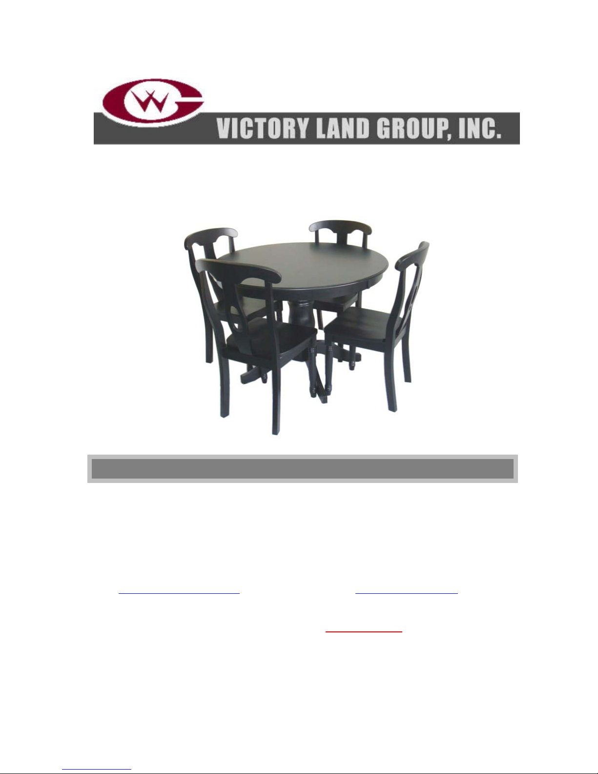
Victory BH084-101-58-19 User manual

5PC Pedestal Dining Set
Item Number: BH084-101-58-19
If parts are missing, DO NOT return to the store. To order missing or replacement parts, please
call 1-800-933-0527. All parts except for the tabletop and center post are replaceable.
THIS INSTRUCTION BOOKLET CONTAINS IMPORTANT SAFETY
INFORMATION. PLEASE READ AND KEEP FOR FUTURE REFERENCE.
Purchase Date: ____________________________ Lot Number: ____________________________
Please save and attach your sales receipt to this Assembly Instruction Booklet.
CUSTOMER SERVICE INFORMATION
Victory Land Group, Inc
1350 Munger Rd
Bartlett, IL 60103
WEB:http://www.victorylandgroup.com
PHONE: 1-800-933-0527
FAX: 1-630-540-7099
8:30 am to 5:00 pm CST, Mon. thru Fri.
EMAIL: h[email protected]m

1
1. Chair-maximum load weight per chair is 300 pounds.
2. Table-maximum load weight on table top is 350 pounds.
The manufacturer warrants to the original consumer-purchaser that this product shall be free
from defects in workmanship and materials under normal and reasonable use when assembled and
operated according to this Instruction Manual from date of purchase as follows:
One Year
The manufacturer will, at its option, refinish or replace any product or part found to be defective during
the limited warranty period. There may be a shipping charge. The manufacturer may require you to
return the part(s) claimed to be defective for its inspection, freight or postage prepaid.
Contact our Customer Support Center as shown above before returning any part(s).
The manufacturer will require reasonable proof of purchase. We strongly recommend you keep
your sales receipt.
You can attach your receipt to this manual.
This limited warranty does not cover the cost of any inconvenience or property damage due to failure of
the product and does not cover damage due to misuse, abuse, alteration, improper or failure to perform
normal and routine maintenance, discoloration, scratches, rust, accident, damage arising out of
transportation of the product, or normal wear and tear.
This limited warranty will not apply to any 5PC Pedestal Dining Set used for commercial use.
This limited warranty is the sole warranty given by the manufacturer and is in lieu of all other warranties;
express or implied, including implied warranty of merchantability or fitness for a particular purpose.
Neither manufacturer dealers nor the retail establishment selling this product have any authority to make
any warranties or to promise remedies in addition to or inconsistent with those stated above.
This limited warranty applies only to products sold at retail, and is not transferable.
The manufacturer's maximum liability, in any event, shall not exceed the purchase price of the product
paid by the original consumer-purchaser.
Some states do not allow the exclusion or limitation of incidental or consequential damages.
Therefore, the above limitations or exclusions may not apply to you. This warranty gives you specific
legal rights and may also have other rights, which vary from state to state.
MAXIMUM RECOMMENDED WEIGHT LOADS
LIMITED
WARRANTY

2
1. Please read the Assembly Instructions prior to assembling this product.
2. To avoid damage, assemble the product on a non-abrasive surface such as carpet.
3. Make sure all screws, nuts, and bolts are tightly fastened before the product is used.
4. Not for Commercial Use
5. Keep all 4 legs of the chairs on the ground when using them. Do not rock or tip back in
the chairs.
6. Care: Use a soft, clean cloth that will not scratch the surface when dusting. Never use
water to clean your furniture as it may cause damage to the finish. Using solvents of
any kind on your furniture may damage the finish. Always use coasters for beverage
glasses and protective pads under hot dishes and plates. Liquid spills should be
removed immediately, use a soft clean cloth; blot gently and avoid rubbing. Avoid
prolonged exposure to moisture and sunlight.
7. Estimated assembly time is fifty minutes when 2 people are assembling.
GENERAL INFORMATION
,
TIPS
,
& TRICKS
Please make sure you have all parts before beginning assembly. Please wait until all steps are
completed before tightening bolts and nuts. We recommend using two people for assembly.
1. Use the long end of the Allen wrench to fasten Allen bolts loosely and quickly.
2. Use the short end of the Allen wrench for final tightening.
A Phillips head screwdriver is necessary for assembly. It’s not included in
hardware list.

3
A. Tabletop B. Connector Panel
QTY: 1 pc QTY: 1 pc
C. Center Post D. Leg
QTY: 1 pc QTY: 4 pcs
TABLE PART LIST

4
1. Nut 2. Spring Washer 3. Flat Washer
5/16 inch Dia 5/16 inch Dia 5/16 inch Dia
QTY: 8 pcs QTY: 12 pcs QTY: 12 pcs
4. Long Allen Bolt 5. Adjustable Foot
5/16 Dia x 1-1/4 inch L
QTY: 4 pcs QTY: 4 Pcs
6. Open-End Wrench 8. Short Allen Bolt
1/4 Dia x 1 inch L
QTY: 1 pc QTY: 4 pcs
7. Allen Wrench
QTY: 1 pc
TABLE HARDWARE LIST

5
REQUIRED HARDWARE IN THIS STEP
NO.DESCRIPTION SKETCH QTY
1 Nut 8 pcs
2 Spring Washer 8 pcs
3 Flat Washer
8 pcs
6 Open-End Wrench
1 pc
ASSEMBLY INSTRUCTIONS-
TABLE
1. Place center post (C) upside down on a
non-abrasive surface such as carpet. Attach
legs (D) to the center post (C) using nuts (1),
spring washers (2) and flat washers (3) as
instruction (a). Tightly fasten the nuts with
open-end wrench (6).
C
D
D
D
D C 1
2
3 6
1
2
3
a
Top

6
2. Screw the adjustable feet (5) into the pre-drilled holes on the bottom of the legs (D) as
instruction (a).
REQUIRED HARDWARE IN THIS STEP
NO.DESCRIPTION SKETCH QTY
5 Adjustable Foot
4 pcs
ASSEMBLY INSTRUCTIONS-
TABLE
D
D D
D D
5
Top
a

7
3. Turn the assembled pedestal upright. Attach connector panel (B) to the center post (C)
using 5/16 Dia x 1-1/4 inch L long Allen bolts (4) as instruction (a). Tightly fasten the
Allen bolts withAllen wrench (7).
REQUIRED HARDWARE IN THIS STEP
NO.DESCRIPTION SKETCH QTY
4 Long Allen Bolt 4 pcs
7 Allen Wrench
1 pc
ASSEMBLY INSTRUCTIONS-
TABLE
C
B
B
a
4
7

8
4. Place the tabletop (A) upside down on a non-abrasive surface such as carpet. Attach
the base of the table to the tabletop (A) using spring washers (2) and flat washers (3)
and 1/4 Dia x 1 inch L short Allen bolts (8) as instruction (a). Tightly fasten the Allen
bolts withAllen wrench (7).
REQUIRED HARDWARE IN THIS STEP
NO.DESCRIPTION SKETCH QTY
2 Spring Washer 4 pcs
3 Flat Washer
4 pcs
8 Short Allen Bolt 4 pcs
7 Allen Wrench
1 pc
ASSEMBLY INSTRUCTIONS-
TABLE
B A
B
a
8
2
3
7

9
Please note: You can adjust the feet (5) to level the table.
The table is now ready to use.
ASSEMBLY INSTRUCTIONS-
TABLE
ADJUSTABLE
FOOT
350 pounds (158.76 kg )
Maximum
Recommended
Weight Loads

10
E. Chair Back F. Front Legs
QTY: 4 pcs QTY: 8 pcs
G. Seat Frame H. Chair Seat
QTY: 4 pcs QTY: 4 pcs
CHAIR PART LIST

11
1. Nut 2. Spring Washer 3. Flat Washer
5/16 inch Dia 5/16 inch Dia 5/16 inch Dia
QTY: 16 pcs QTY: 44 pcs QTY: 44 pcs
9. Long Bolt 11. Wood Screw
1/4 Dia x 3 inch L
QTY: 16 pcs QTY: 12 pcs
10. Short Bolt
1/4 Dia x 1-3/4 inch L
QTY: 12 pcs
CHAIR HARDWARE LIST

12
REQUIRED HARDWARE IN THIS STEP
NO.DESCRIPTION SKETCH QTY
1 Nut 4 pcs
2 Spring Washe
r
4 pcs
3 Flat Washer
4 pcs
6 Open-End Wrench
1 pc
ASSEMBLY INSTRUCTIONS-CHAIR
1. Remove the plastic plugs protecting the bolts from the
front legs (F). Attach two front legs (F) to seat frame (G)
using nuts (1), spring washers (2) and flat washers (3).
Don’t tighten the nuts at this time.
Note: The chair seat frame (G) has one screw hole in each
side and one in the front to attach the chair seat at a later
step. These holes are wider on the bottom and narrower
on the top. Ensure the wider holes look down towards
the bottom of the chair legs (F).
a b
G
F
F
F
Ensure wider end of
holes face towards
the bottom of the
chair le
g
s
PLASTIC PLUG
G
1
2
3
1
2
3
6

13
REQUIRED HARDWARE IN THIS STEP
NO.DESCRIPTION SKETCH QTY
2 Spring Washer 7 pcs
3 Flat Washer
7 pcs
6 Open-End Wrench
1 pc
9 Long Bolt
4 pcs
10 Short Blot
3 pcs
ASSEMBLY INSTRUCTIONS-CHAIR
2. Attach the seat frame (G) to the chair back (E) using long
bolts (9), short bolts (10), spring washers (2) and flat
washers (3) as instructions (a&b).
3. Turn the chair upright. Tightly fasten all bolts and nuts
ensuring the chair remains level.
E
G a b
E
G
10
2
3
10
2
3
6
6 9
2
3
9
2
3
10
2
3

14
4. Place chair seat (H) upside down on a non-abrasive table surface. The rear (tapered
end) of the chair seat (H) should be near the table edge.
Hint: Protect the non-abrasive table surface and chair seat (H) by laying a towel
in-between the chair seat and table.
5. Place the assembled chair frame on the chair seat (H) as shown. Attach with wood
screws (11).
REQUIRED HARDWARE IN THIS STEP
NO.DESCRIPTION SKETCH QTY
11 Wood Screw 3 pcs
ASSEMBLY INSTRUCTIONS-CHAIR
a
E
G
H
G
11

15
6. The Chair is now ready for use.
7. Repeat the steps 1 to #6 to assemble the other chairs.
Printed in Vietnam
ASSEMBLY INSTRUCTIONS-CHAIR
300 pounds ( 136,08 kg )
Maximum
Recommended
Weight Loads
Table of contents
Other Victory Indoor Furnishing manuals
Popular Indoor Furnishing manuals by other brands

Lifestyle Solutions
Lifestyle Solutions RETRO BED Assembly instructions

Argos
Argos Aruba 617/2602 Assembly instructions

Furniture of America
Furniture of America CM-AC6931 Assembly instructions

SAFAVIEH COUTURE
SAFAVIEH COUTURE Teresa SFV8717A quick start guide

Southern Enterprises
Southern Enterprises EN836100TX Assembly instructions

Otto
Otto 323494 Assembly instructions